R.Hasika - a precise and compact robot base (rpi)
A precise and upgradable robot base built around a raspberry pi
A precise and upgradable robot base built around a raspberry pi
To make the experience fit your profile, pick a username and tell us what interests you.
We found and based on your interests.
R.Hasika_perfboard.fzzPerfboard version of the circuitfzz - 22.50 kB - 03/15/2016 at 04:08 |
|
|
chassis_tank_18650_monocoque.scadThis is the scad file used to generate the chassis parts. At the end of the files are two lines : comment one for the bottom part, and comment the other for the top part. It uses the lipoBattHolder.scad file, that must be in the same folder. Please print this other part before to test with your batteries before, and adjust size if needs be.scad - 18.53 kB - 02/20/2016 at 00:29 |
|
|
lipoBattHolder.scadA simple lipo battery holder openscad file. I use it to plug longer lipo cells with battery protection board. This part is used 4 times in the robot. prior to printing the robot, print one of those, and check that it's the good length for your batteries. If not, adjust until you have a good fit. Then print the robot chassis, it will be updated properly.scad - 2.52 kB - 02/20/2016 at 00:27 |
|
|
chassis_tank_18650_monocoque_stage2_frame.stlThis is the stage 2 of the chassis, where the Raspberry pi gets screwed on, the lipo charger, and the sensors. It screws on top of the bottom part of the chassis. It has holes to add another layer and a top cover.Standard Tesselated Geometry - 389.60 kB - 02/19/2016 at 23:31 |
|
|
chassis_tank_18650_monocoque.stlLower part of the R.Hasika chassis. It's mostly closed towards the bottom, with 8 holes : two pairs for screws holes to secure the motors, two holes for the motors axis, and two for the idle sprocket blocks. In contains room for 4 lipo 18650 cells, and wire management. Once everything is screwed in position, it is almost waterproof.Standard Tesselated Geometry - 348.33 kB - 02/19/2016 at 23:28 |
|
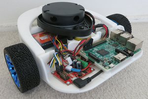
Last night, i finished rebuilding the electronics board, and i could assemble a functionnal version of R.Hasika. Things are still not yet there, but there was enough stuff to try a simple algorithm.
So i reassembled the robot, and once things were mostly in place i got this :
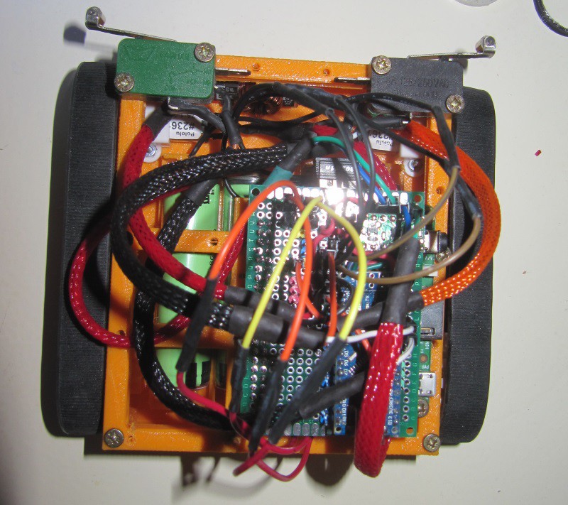
Anyway, i could use the Arduino board to control the motors, and the contact switches i the front did work. I was able to get the robot to execute a simple obstacle avoidance algorithm, as seen in this video :
After the video, i did some other work on the robot (adding a distance sensor, a power button, LED), giving the followig result :
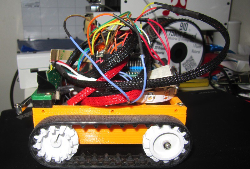
This board goes over the Raspberry pi. It is not shown here, but a 2*20 female header is soldered on the board. The electronics board is thus plugged onto the raspberry pi (as a hat in fact, later on i should try to add an eprom to comply with HAT standards).
Here is the base schematics :
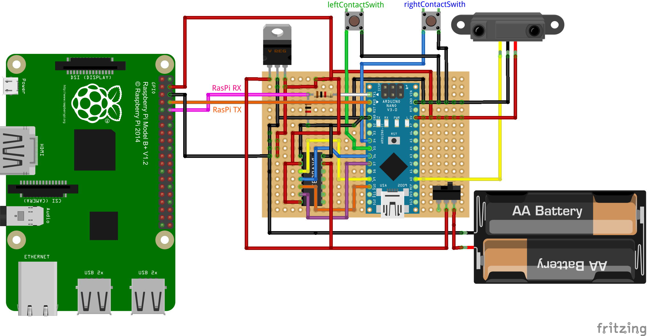
You can download the Fritzing file following this link.
The IC depicted on the board is a DRV8835, but i don't have the part for Fritzing. It's in DIP14 anyway.
I didn't put the motors ouput wires because it would make the schematics unreadable. i'll find a way to do so.
In the meantime, here is the schematics of the DRV8835 board : 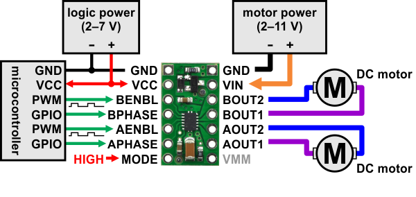
I made this board, but due to a faulty switch, the blue smoke got out. I didn't understand that the switch was defective at that time, and dismantled the board trying to figure that out, after testing many continuity points.
I'll remake the board soon, as it is the last step to a functional R.Hasika.
See you soon for the next update :)
Hello there!
I decided to change the chassis conception. Rather than laser cut it, i decided to make it in plastic (3D printed). The reason behind this is to simplify assembly, and make everything more solid and weatherproof.

I thus decided to make the lower part of the chassis a monopart design. It is thus meant to be printed in one piece, so no assembly on this part. It is mostly closed on the bottom and sides : there are only 8 holes :
You can see the 3D design here :

The front and back are curved, so that it doesn't get stuck on obstacles. The chassis is slightly shorter than the tracks, so that the tracks can grip on obstacles rather than having the chassis bumping into it.
The batteries are as low as possible on the chassis without hindering ground clearance (as high as possible with those tracks), and take place directly on the bottom.
With batteries, motors and motor rotation sensors, the bottom of the chassis weights approximately 400-430g.
It is meant to get 18650 lipo cells (4 of them). I designed it to have long lipo cells, those with high capacity and protection circuit. In my case, i used 4 3400mAh (official capacity, but also what i measured) cells. That's a total of 13.6Ah at 3.7V, thus storing 50Wh of energy.
The Raspberry pi on standby is aproximately half a watt, so 100 hours of idle runtime. The motors draw 1.6A max, so 3.2A max, at stall, meaning that in the worst case, i'll get 4.25 hours of moving time, in the WORST case.
More realistically, the motors will draw 200-300mA each, so let's say 600mA for both, +300 for the pi, the wifi activated all the time, and various sensors, the camera module, etc, so let's round it at 1A while moving. It will still provide 13 hours of moving time, with all systems on.
Compared to the previous 6.6Ah pouch battery, those 18650 are :
According to my calculation, those batteries provide 250Wh per kilogram, which is excellent, considering that lipo are given up to 270.
Plus those are metal cells, so more solid than the previous ones. I did pay 30$ for the 6.6Ah pouch cell back then, whereas i paid 35-40$ for 10 lipo cells of 3.4Ah, so 34Ah of total capacity. Cost wise, it's much better. It's more modular (i could make a chassis with 2 cells, and more capacity, or make it larger, and double the capacity if i wanted to..), it provides better efficiency (less mass for same capacity or more capacity for same mass), they are more solid, better quality (i know the origin of the cells -panasonic-, and they are good quality cells).
All in all, i won't be using pouch cells anymore, unless i need really flat batteries. Here is the link to the very model i bought :
Yes, i bought it from china, but it doesn't mean it's chineese ultrafire batteries. I have tested the cells with a good charger (full charge then full discharge at 1A, i got 3430mAh or things like that on the 4 batteries i used on the robot (4 at random among the 10, i didn't test all 10).
For cheaper (25€ for a 10 pack), those batteries are also available, but they are 2.6Ah, same size. This time, samsung sells, i didn't test their real capacity yet, but they seem to be real batteries.
As for the battery box, i could have used something like this (and i bought a 10 pack). However, those boxes are too short : the protected...
Read more » As seen in a previous project log, i have two plates for this robot. The lower one sports the battery, charge circuit, power regulator, motors, ultrasonic sensor and the motor driver.
The top plate supports the "brains" of the robot, i.e. command electronics. This means a Raspberry pi, an Arduino uno (for now, later it will be a a more compact Arduino compatible circuit, once i design it and have everything i decide what i want to include on it). More sensors are to be included, such as a camera module for the raspberry pi, along with a servomotor to orientate it.
As of now, i also have micro switches to detect collisions, and some room for a half size breadboard.
The question here was how to connect the two stages, and pass cables from one to the other. I decided to design a support structure specially for that. Since a plane needs three points to be defined, i chose to use three support structures. Those beams had to be strong enough to provide stability to the top plate, while being simple to print, identical, with the ability to pass cables through it. Here is what i designed :
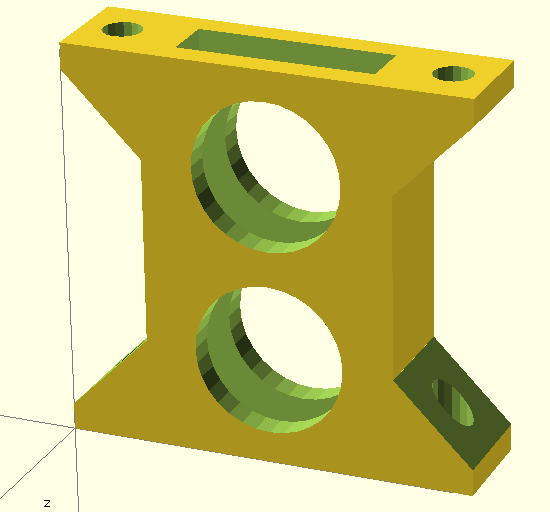
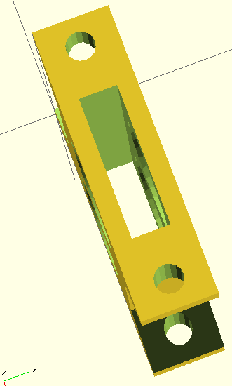
This beam is symmetric so that the up and bottom are identical, left and right and front and back also, making it easy to mount, since you just put it where it goes, with no worry about orientation. If it screws, it is how it should go.
Globally, it is a hollow box, with 2mm thick walls. I cut two holes to not only save material and print time, but also to pass cables. The rectangular opening that goes from top to bottom serves the same purpose.
Indeed, some cables have to come from the underside of the robot, to the top of the bottom plate, and other cables goes from the top ob the bottom plate to the top of the top plate through those beams. Female and male jumper wire fits in, however, in the next version, i will make the beam slightly higher, and the round holes a bit more elliptic to facilitate the insertion of the connectors of the jumper wires.
For this robot, three of these beams have to be printed :
 You can also follow this link that leads to a larger version of this picture, on my wiki.
The piece has two foots on top and on the bottom, with 3 mm diameter holes, for screwing this to the plates. It works perfectly with M3 machine screws, without a nut.
Once installed, this is how it looks :
 Of course, the chassis plate have been designed to work with those beams, as not only the screw holes are present, but rectangular cuts on top and bottom, aligned so that this positions the top plate adequately in relation to the bottom plate.
Here is thescad file to download if you want to adjust the beam (walls thickness, height, etc), andhere is the stl file i used for those prints, with a beam height of 35mm, ready to print.
I printed those in PLA on my printrbot simple metal at fast speed, in 0.3mm layers, with no problems :
 I could have printed it nicer, but it does the job perfectly as is.
It used 1200mm of filament per beam, for an individual print time of 30 minutes.
See you next!
The motors of the robot are mounted under the base plate. They are equipped with magnetic quadrature encoder disks, fitted directly on the motor axis prior to the gearbox. This wheel thus has no torque, and if something touches it, it will stall the motor. Furthermore, there are cables with fragile connections leaving the sensor board.

Long story short, there are sensitive parts that needs to be protected. In order to do so, i designed a protection in openscad :
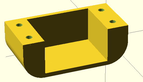
The front and back sides are rounded, so that an obstacle on the ground hitting this part will slide onto it rather than getting the robot stuck.
There is one protection per motor, and the two pieces are identical, so that they are interchangeable. I am using generic parts as much as possible for this robot rather than a specific part for the left or right, as much as possible. This simplifies the design, but also the logistics and construction, since the piece that fits is the good one :) .
The piece has 3mm screw holes, and M3 machine screws works well out of the box, without the need of a nut.
Once in position, this is how it looks :
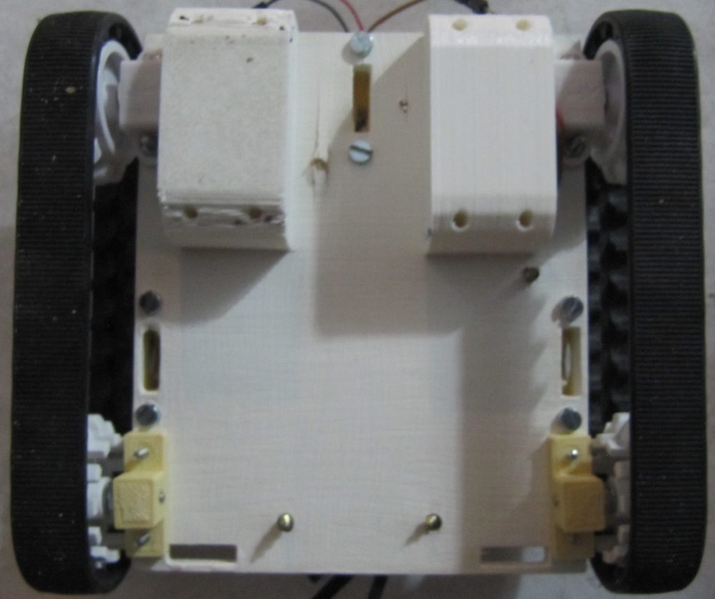
The left one was printed with the underside on the printbed, causing bridging problems. The left part was printed with the other flat side of the part on the bed, causing a much better print.
Here is the link to the scad file for this motor protection, and here is the link to the stl file for this motor protection. I printed it with a printrbot simple metal, in PLA. Those links are for a revised version of this part. I increased the curve level (same shape, but a "rounder" curve, with more segments). This causes a smooth curve rather than the "steps" visible on the right part (i printed and tested one, to replace the left one).
Don't forget to rotate the part for best results! I will update the stl file so that it is already oriented correctly. There is another advantage to printing this way : the layers causes little lines on the print. When printed rotated, the lines are in the same direction of the movement of the robot, causing less friction than in the other way.
A small update today, about the main power switch.
Previously, i had a small power switch on the breadboard to turn the robot on and off. It was highly impractical, since when you wanted to shut the robot down, not only you had to run after it and catch it, but also reach the switch within the robot. I thus decided to add a bigger button, in a more accessible position. I used a latch pushbutton with an integrated LED :
I soldered flexible silicon wires from Adafruit, and used heatshrink tubes to clean it. These wires are really flexible, and are easy to route in the robot.
The LED turns on when the robot turns on, and the switch controls the power output of the battery. If the switch is off, no energy is used. The led also add a "cool factor", which is fun :) It looks like an eye, perhaps later i'll put a "breathing" effect to it.
At this point, i had to find a solution to secure it to the robot. It had to be easily accessible, but not too exposed. I decided that it would be on the back of the robot. I designed a fixation with openscad :
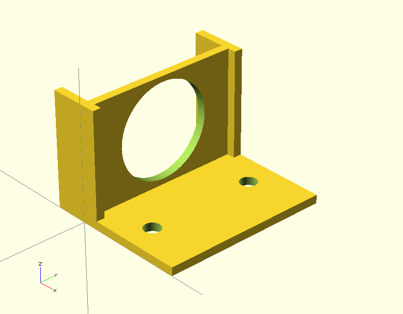
Here is a link to the scad file to the button fixation holder, and a link to the stl file for the button fixation holder.
I added 5mm on each side of the piece, in the front, in order to keep the robot for powering down after a contact with a wall.
I will add a retractable cover later (transparent, of course).
Once everything is in position, this is how it looks (back view of the robot) :
I yet have to update the robot plans for laser cut to add the screw holes for this part.
See you next :)
Unlike my previous robot, whose chassis where simply a wooden plate approximately cut and drilled, i decided to construct the chassis only after thoroughly designing it. I thus searched an open source 3D modelling soft, and happened to really enjoy OpenScad. This software enables the user to program rather than click, constructing 3D shapes by combining and altering primitives volumes. Using this, i designed my chassis plates in a parametric way.
First of all, i defined all constraints, such as the motors screw holes diameter, position relative to the edge, distance between front and back wheels (i decided to use 4 wheels, with two motorized ones, and tracks). All those parameters are fixed due to the parts that i chose to use.
I thus have a fixed robot length, but the width can be set by the user (the length can too, but by setting the distance between front and rear wheels, and motor parameters, not directly, although i may include a variable to increase the length).
At this point, we have the base dimensions for the base plate. A second layer is automatically defined, depending on the size of the first layer, but larger (top layer width=bottom layer width + 2* tracks width) and longer.
The first layer contains the lipo battery, a sensor, the charge circuit for the battery, and a small circuit area, with the motor driver and the switching regulators.
I calculated the ideal motor screw holes positions, depending on the Pololu specifications for my motors (micro metal gearmotors) and fixations. In order to be able to use 2 or 4 motors, the same holes are present in the back and in the front. We will figure later how to attach the free-spinning wheels. The motors can be either in the front or the back.
In this version, the motors will be on the underside of the level 1 plate, so i added rectangular cuts in the chassis near the motors to pass the cables. The top layer have the same cuts so that cables can be run from one to another layer.
Here is a projection in 2D :
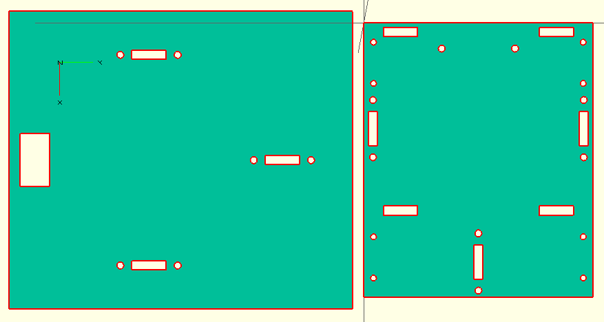
On the left, the top plate, on the right, the bottom plate, rotated by 90°.
You can also download the DXF file of the chassis, including those two plates.
If you want to modify the file, you can download the scad file for openscad with the full robot, or the scad file with the projection in order to obtain the 2D dxf file.
It can either be laser cut (perhaps with a CNC?), or simply printed, then using a jigsaw you can cut the plates, and drill the screw holes, and motor wires cuts (obciously not a nice rectangle, but some round holes will do).
The code is commented (in english), so one should be able to adapt easily the dimensions.
Please note that this isn't the final version, as i see some adjustments that i'll probably made for the next revision. In order to connect the top and the bottom layer, we will have to design something 3D-printable.
See you in the next update!
For this robot, i am using the general design choices made for R.Cerda, a differential drive robot (link on hackaday.io).
This obviously implies a differential drive robot, meaning that we will use two or for motors, on the left and right. For those motors, rather than just using the plastic gearmotors from pololu that i previously used, i decided to use higher quality motors, the Pololu 75:1 Micro Metal Gearmotor HP with Extended Motor Shaft, each one equipped with Pololu Magnetic Encoder Pair Kit for Micro Metal Gearmotors, 12 CPR, 2.7-18V in order to measure motors rotation. I am hoping that those sensors will enable the robot to drive straight, and accurately measure the movement. We will come back at this in another post.
With those motors, i will be using Pololu 30T Track Set. Those measures approximately 10cm. I chose tracks in order to have a good traction, the capacity to go over obstacles, and the cool factor of tracks. However, i plan to design the robot in a way that enables the user to switch from tracks to wheels in a simple way.
So, wheels and tracks. The chassis will be home made, we'll come back on this point in another post. In order to drive the motors, i will be using a DRV8835, capable of 1.2A continuous and up to 1.5A peak. It has a thermal protection, and can drive each motor with only two pins. One pin is PWM to specify speed, and the other one sets the direction. The chip is capable of handling 2 motors. The problem is that this is a really small component, not in a DIP format, and i won't be able to solder it. Thankfully, i found the Pololu DRV8835 Dual Motor Driver Carrier (otherwise, i would have used another chip). Another advantage of those chips over L293D or SN754410NE is that for this one, we can have a vMotor as low as 2V, compared to 4.5-5V for the other chips. This leads us to the next point : power.
I chose to use Lipo battery rather than NiMH AA batteries because of the superior energy density, and the vast amount of charge circuits available for LiPo. Furthermore, many of those circuits are able to charge the device while it functions, removing the need to power down the robot for charging. It is probably possible to do something similar with NiMH, but i don't know where to source such circuits, or how to design those. Furthermore, the increased battery capacity won't hurt here. The drawback is the lower tension (3-4V with one lipo cell), since i want to restrict the choice to 1S lipo batteries to keep things simple. I selected a 6000mAh 3.7V Lipo battery from "i don't remember where i bought it", but Adafruit sells an even larger one , a 6600mAh lipo pack.
For charging purposes, they also sell an USB LiIon/LiPoly charger- v1.2 which i'll be using. It can charge up to 1A, and can charge the battery while providing power to the circuit. It accepts USB as a power input, but also a jack, and has pins for other types of inputs. It has pins that can be read by a µC to check if charging is done. I hope to be able to have the robot charging itself when in low power.
I will use an efficient (~80-90%) step-up step-down switching regulator from pololu to generate the 5V for the Raspberry Pi (and for early prototypes, the Arduino).
As for sensors, beside the ones on the motors, there probably will be at least a rangefinder, be it infrared ot ultrasonic (i tend to prefer ultrasonic ones).
In order to control the motors and sensors, i'll use an ATmega, probably at 3.3V so that i won't have to translate logic levels from 5V to 3.3V. In early builds, i'll use a Arduino R3, because , eh, i have one laying around, and it has built in USB. Future builds will use the Atmega at 8Mhz using internal resonator (so that i have less parts). I may probably make a circuit including the regulators, the motor driver(s), the atmega, along with plugs for sensors, power, etc.
I will also be using a Raspberry pi for higher level algorithms. Indeed, the Atmega will be in charge of real time stuffs, PWM, etc, and be controlled over...
Read more »Installing the battery tabs for the 3D printed version
Repeat those operations for each tab. You can wire it the way you want. I chose to have all negative tabs on the motors side and all positive tabs on the opposite side.
Install the motors
Create an account to leave a comment. Already have an account? Log In.
Become a member to follow this project and never miss any updates
 Keith Elliott
 Audrey Robinel
 Roger
Roger
 Russell Cameron