RasmusB
-
Project update without content
04/25/2015 at 15:25 • 4 commentstl;dr - No progress as of last time. I'm considering another display model, and I'm hoping to assemble the final USB keyboard driver soon.
No, neither me or my project are dead, but there hasn't been much happening for a while, mainly because of work.
One setback is that the OLED screen I ordered was cancelled, and then the seller doubled the price when I wanted to re-order it. I'm not eager to spend $100+ on a screen which I'm not sure how to control yet, so I'm looking for other options.
I want to use an OLED screen for two main reasons:
- They are thinner and thus easier to integrate in my build. It may sound stupid when you know that I have around 4.5mm of depth to use in the lid, but you quickly run out of space when considering that I also need to fit a screen carrier, an adapter PCB and all the connectors. Every mm matters!
- It can be more power efficient than an LCD when showing dark content. Since I want to use my Psion mainly for text-based work, it will probably make a difference.
One of the projects I'm following could be a way forward. The latest project log from the DSI display shield project shows that they have gotten another display working. This is very similar to the OLED display I was considering but with higher resolution. This display can be had for around $50 from Asian retailers. The issue remains how to create the high-speed serial interface to drive a modern cellphone screen. The DSI shield project obviously has a working solution (HDMI -> DSI), and I could use that for prototyping. It would consume a lot of power though, and is not suitable for the final design.
There are adapter IC:s that can handle an 24-bit RGB parallel input signal (for example the Solomon Systech SSD2828), but I'd rather find a way to drive it that doesn't involve adapters to keep cost and power consumption down. The Raspberry Pi has had a DSI interface since the beginning, but for some reason the Raspberry Foundation hasn't made the interface available to users. It has been over a year since they showed a working prototype, but there has been no official updates since. The rumor mill has an official launch slated for Q2 2015... fingers crossed! :)
I have also done some more thinking about the USB keyboard I made. I haven't assembled the final prototype yet but it will happen eventually, mostly because I want to learn more about the USB-enabled AVR devices. But I did rethink using USB for the final design, because of the power consumption. It is more power efficient to get a dedicated IC to perform the keyboard functions, so I'll look into that after completing my USB prototype.
-
Just for fun
02/18/2015 at 23:15 • 2 commentsI couldn't help myself :)
![]() The keymap seems to be working now. If you are feeling brave, you can do the same with an Arduino Leonardo and a Psion keyboard.
The keymap seems to be working now. If you are feeling brave, you can do the same with an Arduino Leonardo and a Psion keyboard.Current progress lives in its own branch on GitHub: https://github.com/RasmusB/PsioPi/tree/HW-proto-keyboard
-
Reverse Engineering the Keyboard, Part V
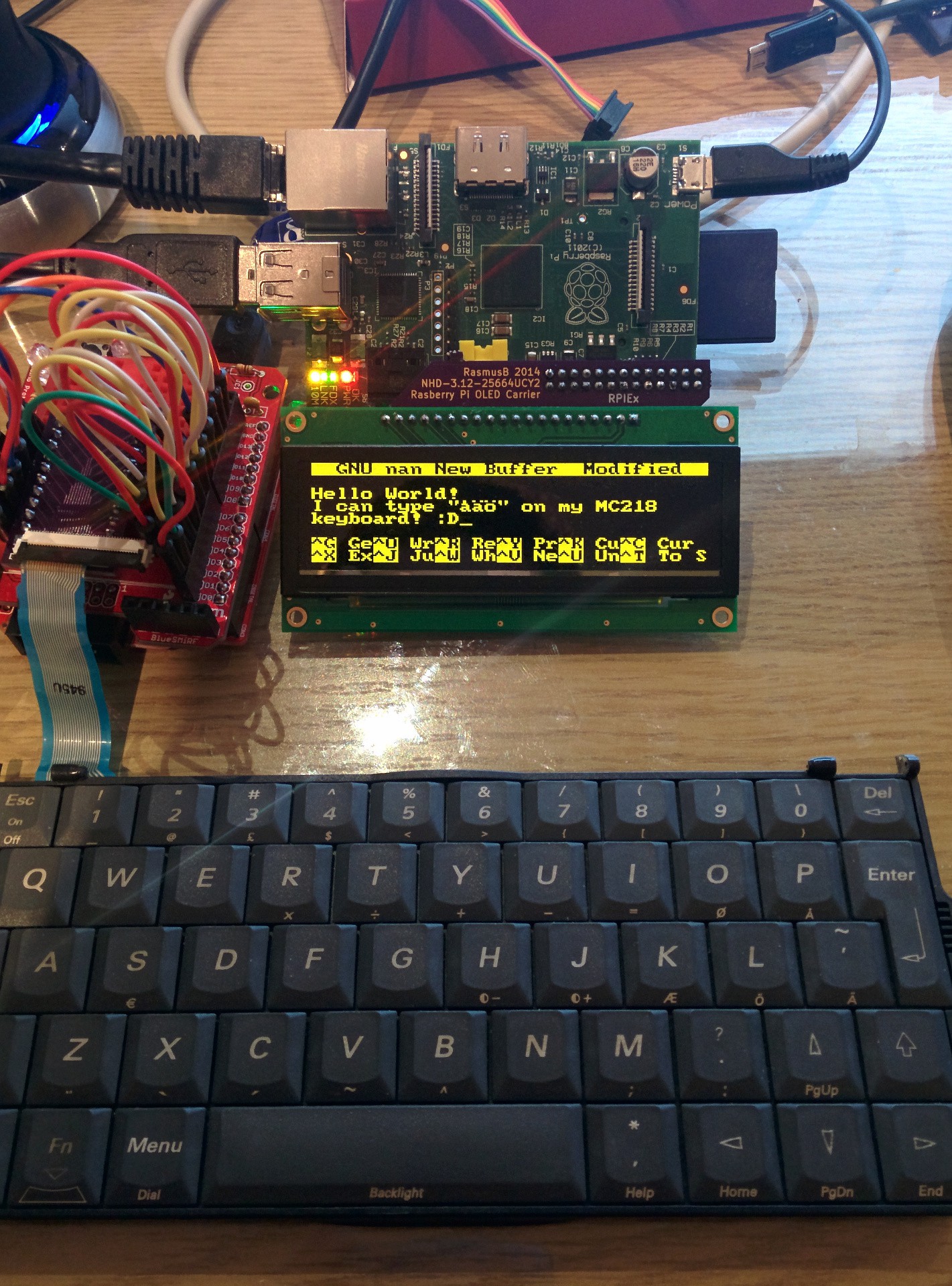
02/18/2015 at 18:44 • 4 commentsHello world!
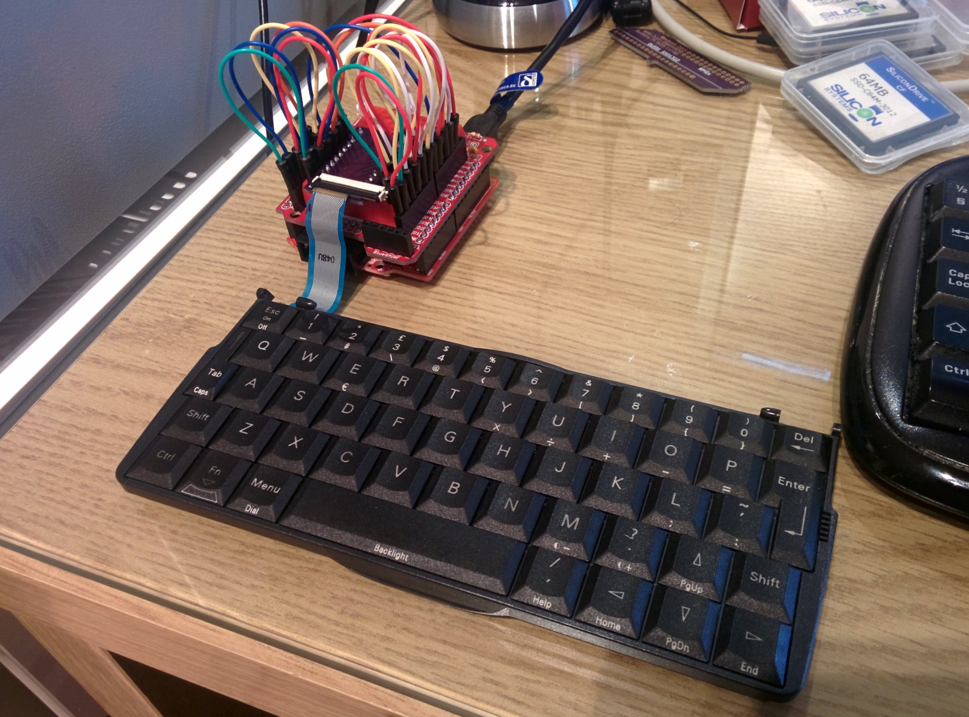
Of course, that was the first thing I typed into my new, beautiful keyboard. Now it is working perfectly, even though it looks a bit messy:
![]()
If you have a really good memory, you'll remember that the keyboard connector is on backorder for another five weeks or so. So what do you do if you don't have the correct connector? You fake one!
I digged around in my parts bins and found a similar connector. It was made for a 0.3mm thick FPC cable, and had the correct 0.5mm pitch. The only difference that mattered was that it had 30 pins instead of 22.
If you are ever faced with this situation, it is VERY tempting to solder the bigger connector centered on your original footprint, like this:
![]()
This is a terrible idea! If I had soldered the connector like this, I would not have had any control over the horizontal position of the cable in the connector. My 22 pin cable can end up being connected to ANY 22 pins between pin 1-30. Or even worse, somehow ending up in some weird middle position where none of my pins are connected. It's a nightmare, trust me.
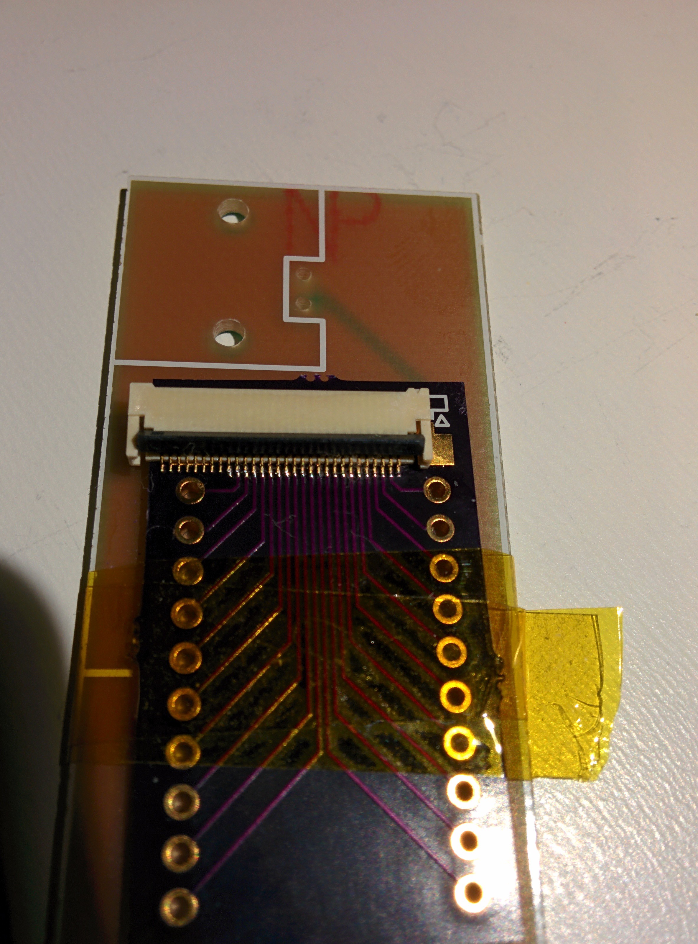
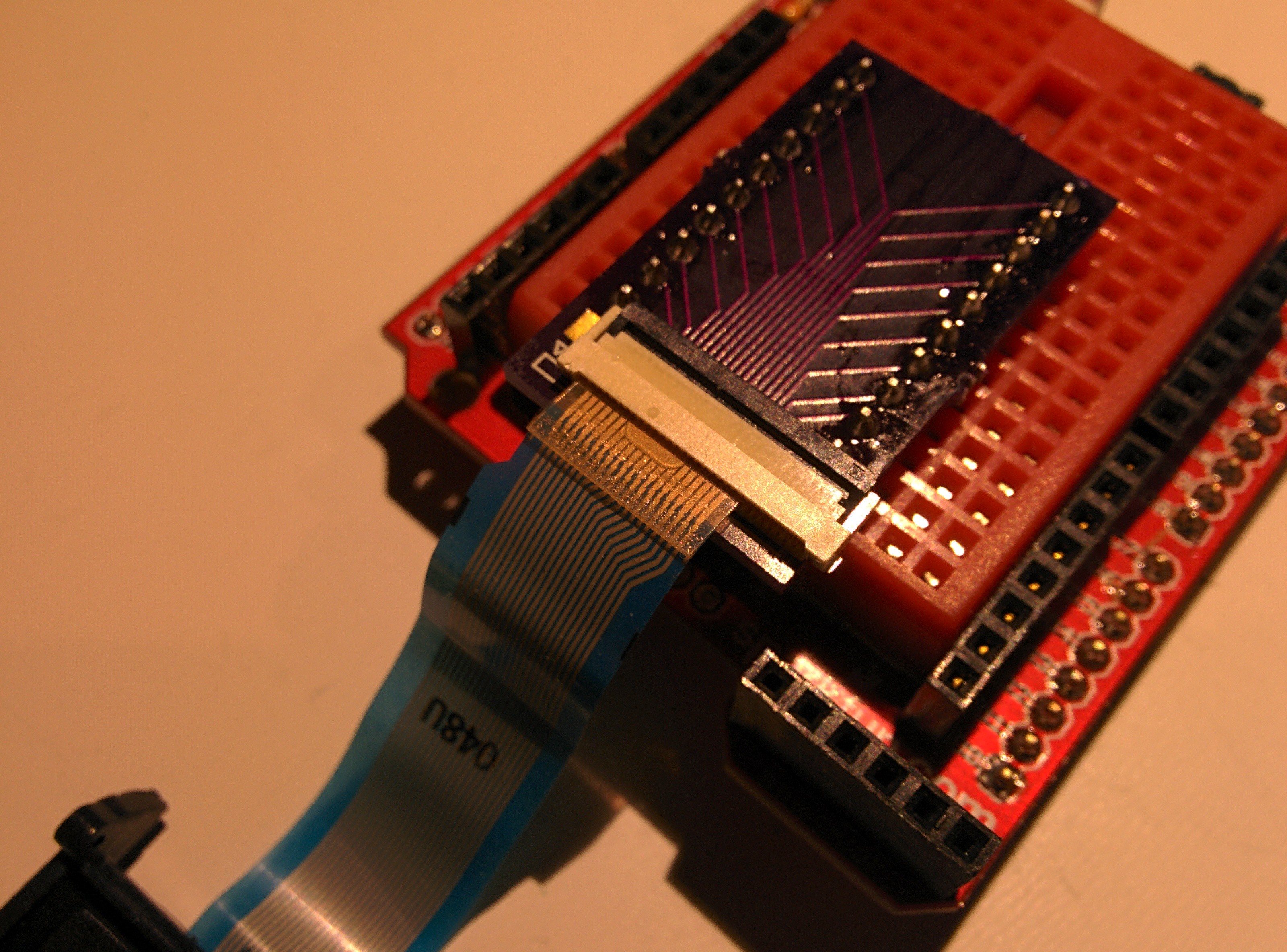
The smarter way is to solder it like this, offset to one side:
![]()
This way, pin 1 on my connector is aligned with pin 1 on the PCB footprint. When I plug my cable in, it will align correctly without effort.
For this job, I also taped the breakout board down to a scrap PCB. This makes it a lot easier to manipulate the small PCB, and it is less likely to slide around when you are trying to get everything aligned.
This is what the finished job looks like after adding the pin headers. Note that even though the connector is offset, the cable is aligned correctly with the PCB.
![]()
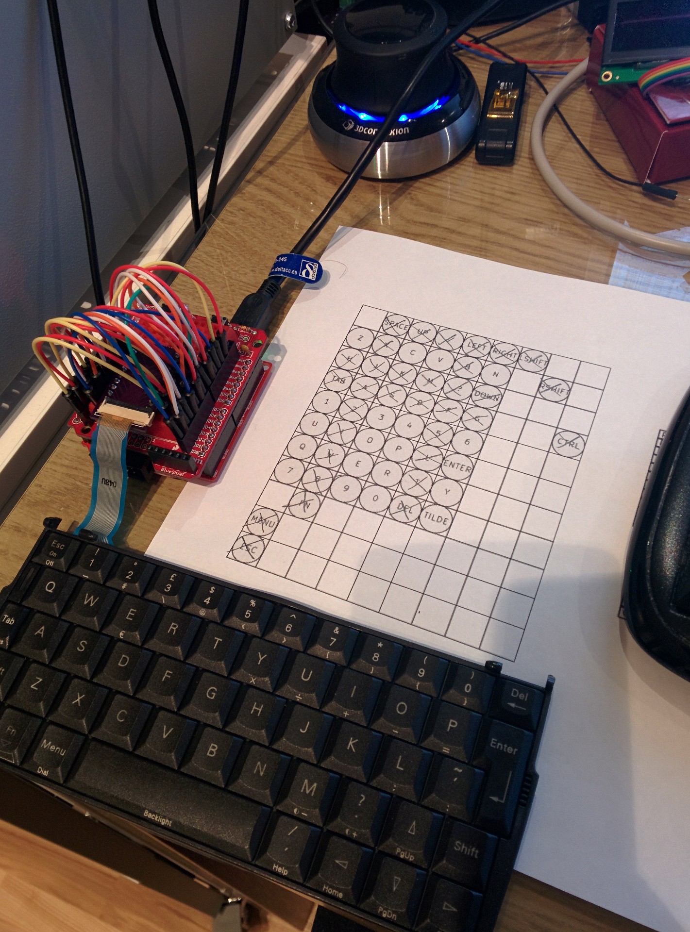
Now it was time to move on with verifying that everything is working. I fired up my firmware, plugged everything in and... it kind of worked. Some keys worked perfectly, but some others were completely dead. I scratched my head quite a bit trying to figure out what the problem was.
![]()
Paper and pencil are excellent debugging tools.
When facing madness, you respond with method. I worked my way through all keys, taking note of which ones worked and which ones didn't. It wasn't a pretty picture, only 18 out of 53 keys were working. I double-checked my wiring, but it seemed correct. Did I somehow break my keyboard when I opened it?
I took apart my "new" MC218 and carefully extracted the Scandinavian keyboard. When I plugged it in, I got the exact same result. So now I knew my problem wasn't in the keyboard.
Next, I suspected that I had made a mistake when tracing the electrical connections in the keyboard itself. I tried disconnecting the keyboard and measuring directly on the cable. This proved to be an exercise in futility, since it is nigh impossible to measure on two 0.25mm wide traces while pressing a specific key. I couldn't even measure anything on the keys I knew worked.
Instead, I thought about it for a while, and then decided to hack together a quick Arduino sketch with a different scanning routine. Instead of having a set of Rows and Columns to scan, it just scans all then pins connected to the keyboard, looking for contact between any two pins. For 20 pins, there are a few combinations to test. How many you ask?
There are 20 pins connected to the keyboard, but since we can't really connect a pin to itself, we have 19 connections for each pin. And since a connection between for example pins 1 and 5, is the same as a connection between 5 and 1, there is one pin less to test for each iteration:
That means that for any key I press, the Arduino has to test 190 different combinations of pins to be sure to find the pin combination for that key. Using my keyboard sketch as a starting point, I soon had a sketch that did this. Then it was just a matter of pushing each button in turn and noting which two pins became connected. I filled in a new spreadsheet while I did this.
There were still a lot of dead keys.
I had ruled out the keyboard, and now I also had ruled out my software, and the wiring logic. The only thing left was my connector board.
Breaking out my USB microscope, I found that the soldering job I felt so good about was horribly botched. Lots of pins were hovering above the pads, not making any connection. I tried fixing it to no avail. That's when you appriciate that OSHpark forces you to order three copies of every board. I found another connector and soldered it down on another board, making sure to make a better job this time. After that, everything worked perfectly!
In retrospect, I should have checked my soldering better. I can not see the problem without magnification even though I know what I am looking for, so double-checking tricky components with my microscope will be the new norm around my lab. I guess I'm getting old. :P
Also, it was actually a LOT quicker to scan my keyboard with the Arduino instead of my manual tracing. It was also more accurate (I found a few small mistakes in my original pinout). If I'm ever doing this with another keyboard, I'll go straight for the automatic approach.
Right now I'm cleaning up the keyboard firmware. I'll also start a project repo on GitHub, where all the schematics and stuff will be available. Then I'll get cracking on the keymap to get all the special characters right. Should be fun, but I'm doing it on my Raspberry just in case. :)
-
Reverse Engineering the Keyboard, Part IV
02/15/2015 at 15:23 • 2 commentsI have made some progress on the keyboard controller since the last log entry.
As we learned last time, our USB keyboard will need to send a specific scancode for each button pressed. All other logic (interpreting the keypresses) is done on the computer side. So we don't really need to bother with which scancodes we are sending, since we can remap everything on the host side anyway.
Other people have used that approach. I tried out a Linux port for the Psion called 'Kludged Linux' and dumped the keymap. The author has just used his own scancodes and mapped them to the correct keys in the keymap. This is perfectly fine for that application, since the keybord will always be connected to the same hardware in the same way. In that case, you can use whatever scancodes you like.
In my case, I'm building an USB keyboard. Even though I'm only planning to use it for this project, it would be nice to keep it as Plug 'n Play as possible. That means that I will use the standard USB scancodes as far as possible, so I can plug it into any computer for testing and prototyping without a custom keymap. I still haven't decided on the main hardware for the project, so an USB keyboard also allows for the most flexibility on that end as well.
So I made a spreadsheet with the following (from left to right):
- USB Scancode
- Kepmap keycode in hex and decimal (just for convenience)
- Row and Col (keyboard hardware mapping)
- What is printed on the keys:
- Primary key function (without modifier keys)
- Secondary function (Shift key pressed)
- Tertiary function (AltGr pressed)
- Matching each combination of modifier keys to the keymap names and format (see man keymap)
Using this, the next step was to write the firmware for my microcontroller. For convenience, I'm using an Arduino-compatible board, Olimexino-32u4. The Arduino IDE had a working example on how to implement a keyboard device and serial port on the same USB connection. (It's really easy)
I actually started out using just the serial connection to debug my code. If I had made a stupid mistake somewhere, I really din't want my first keyboard to spew weird stuff onto my screen and possibly have something nasty happen (like by mistake sending Ctrl+A, Delete and Ctrl+S or similar...). This allowed me to safely test my matrix scanning code with serial debug messages before implementing the 'real' keyboard code.
The current version (1.6) of Ardunio IDE doesn't support sending raw scancodes. Instead, it allows you to send printable ASCII characters and modifier keys. This will no doubt be enough for 95% of USB keyboard implementations, but for me it would add unnecessary overhead to my code (keeping track of what counts as a modifier key and not). Instead, I found a patch that introduces proper scancode functionality, and that seems to work very well!
The code is very straight forward and does not require any additional electronics but the keyboard itself.
- First of all, all pins are set to Inputs. This makes them high-impedance.
- The internal pull-up resistors are enabled on the column pins. This turns them logic HIGH.
- Then, one row at a time is turned to an output and driven low.
- Check the status on the column pins. A logic LOW signal means that column is connected to the active row because that key is pressed.
- When the matrix is scanned, it is compared to the last known state. Then we send 'pressed' scancodes for the newly pressed keys, and 'released' scancodes for the keys that has been released.
- Repeat from step 3.
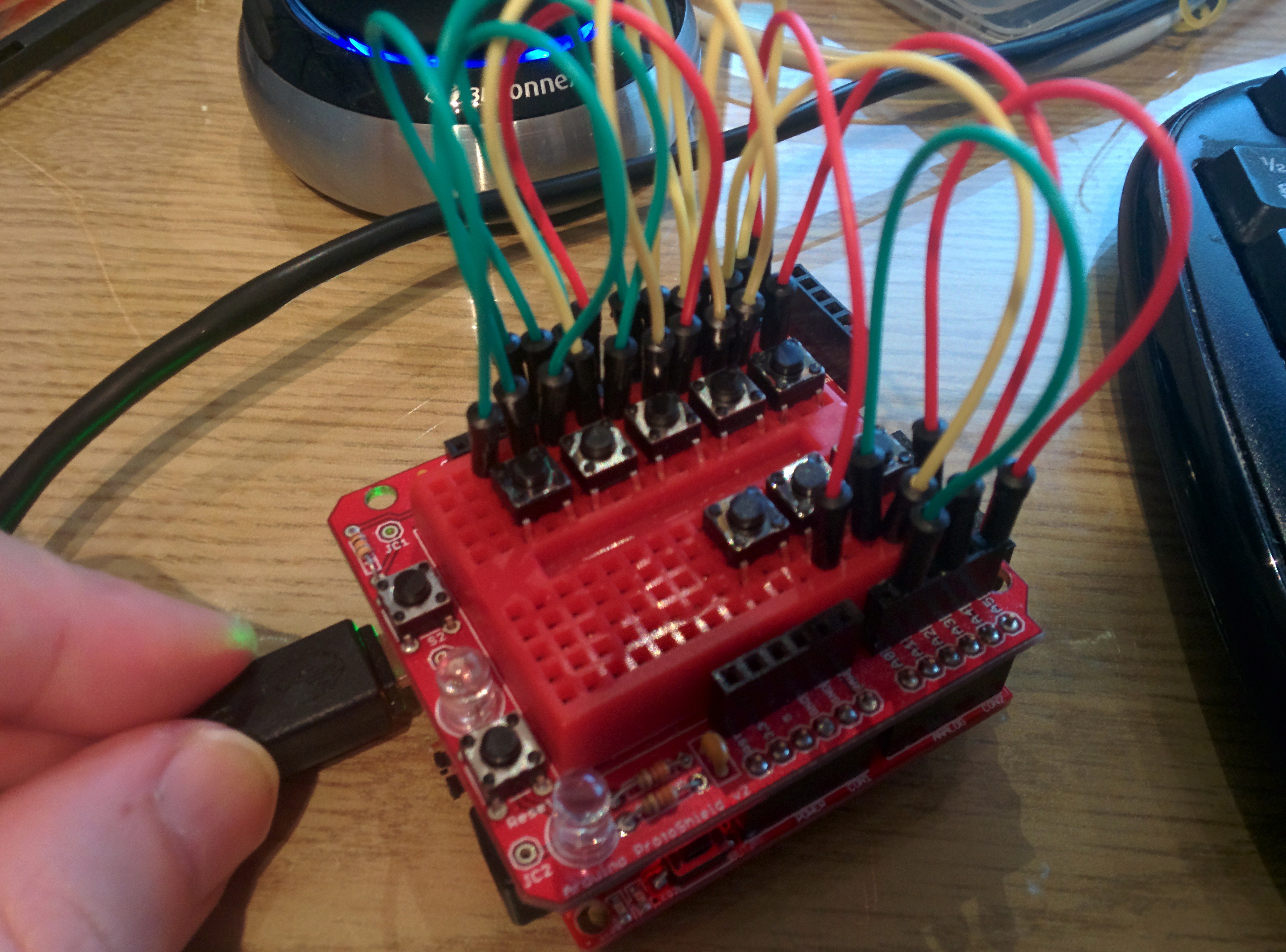
After using the serial port to nail down the last typos in my matrix scanning code, I felt confident enough to try it out! Since I haven't got my adapter for the real Psion keyboard yet, I had to improvise (sorry for the crappy shot):
![]()
As you can see, no other hardware than the buttons themselves are used. I did have to cut a few bridges on the Olimex board to get decent voltage levels since the internal pull-ups are very weak, but that won't be an issue when I do this for real.
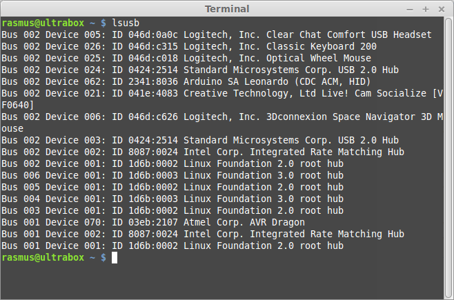
On the USB bus, the 'keyboard' identifies itself as an "Arduino SA Leonardo" running two device profiles: CDC ACM for the serial port, and HID for the keyboard part.
![]()
Anyway, this worked beautifully! I honestly didn't expect this to work as well as it did, considering how simple the code is. But the keys work exactly as you would expect them to on a proper keyboard - keep them pressed and they will repeat at a reasonable rate. Press the shift key and you get a capital letter, and so on. I even tried connecting it to my Raspberry, and it worked perfectly there as well.
The next step is to strip this down. I will make my own custom PCB with just the absolute necessities: the ATmega32u4, a USB connector and a keyboard connector. In its final incarnation, the keyboard controller will live as an integrated component on the main PCB. Before I get that far I want to be sure that I know how to wire the uC up so I don't make any silly mistakes on the more expensive board.
-
Reverse Engineering the Keyboard, Part III
02/13/2015 at 21:33 • 0 commentsTo figure out how to properly implement a keyboard, we first need to learn how a modern USB keyboard works. We'll figure this out step by step.
The first question to answer is deceptively simple: how does my computer know what button i just pressed?
When you connect an USB keyboard to your computer, it will identify itself as a keyboard, which are part of a special USB device class. Since they follow the specification on how a keyboard is supposed to communicate, they "just work" when we plug them in - no drivers needed. But there is something that we do need to configure before it works as expected.
If you have ever used a different (non-american) keyboard, you will probably recognize settings like these:
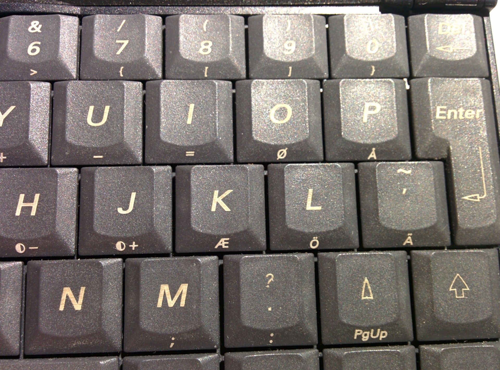
The screenshot is from Linux Mint on my main computer, but there is a similar setting in Windows, OSX and so on. You'll notice that I have selected "Swedish" for my keyboard layout, even though the GUI language is set to English. That is because I have a "Swedish" keyboard connected to my computer, and it shares it layout with this keyboard:
![]()
When compared to an American keyboard layout, the number of keys are the same. But there are some extra letters, and some of the special characters has moved around. For example, look at the button to the right of 'L'. On the Swedish layout, it is labeled 'Ö', but on an American layout you would instead find ';' in the same position.
So the layouts are different, big deal! Why do we care? Why do we even need to select the proper layout?
This is a very important point: the keyboard does not know its own layout.
This means that the only real difference between a Swedish and an American keyboard are the symbols printed on the keys - the signals sent to the computer are exactly the same. How can we prove this?
We can look at what is actually happening by sniffing the USB traffic. This is very easy to do under Linux, I followed these instructions: http://wiki.wireshark.org/CaptureSetup/USB (note that you need to run Wireshark as root for USB packet sniffing)
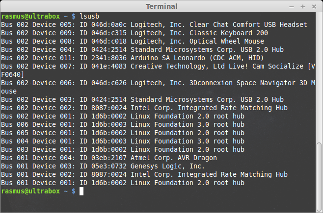
First we need to know the USB bus our keyboard is connected to:
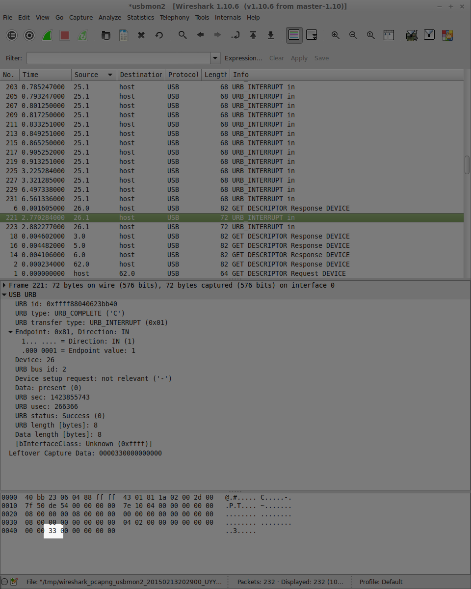
On the second line, we find the keyboard as device 26 on bus 2. I then captured bus 2 in Wireshark, pressed the 'Ö' key and saw this:
Look at the highlighted area near the bottom where it says '33' in hexadecimal. We can find 33 in the scancode table on this page. Somewhat confusingly, is also says that that '33' means that the ';' key was pressed, even though I really pressed the key labeled 'Ö'.
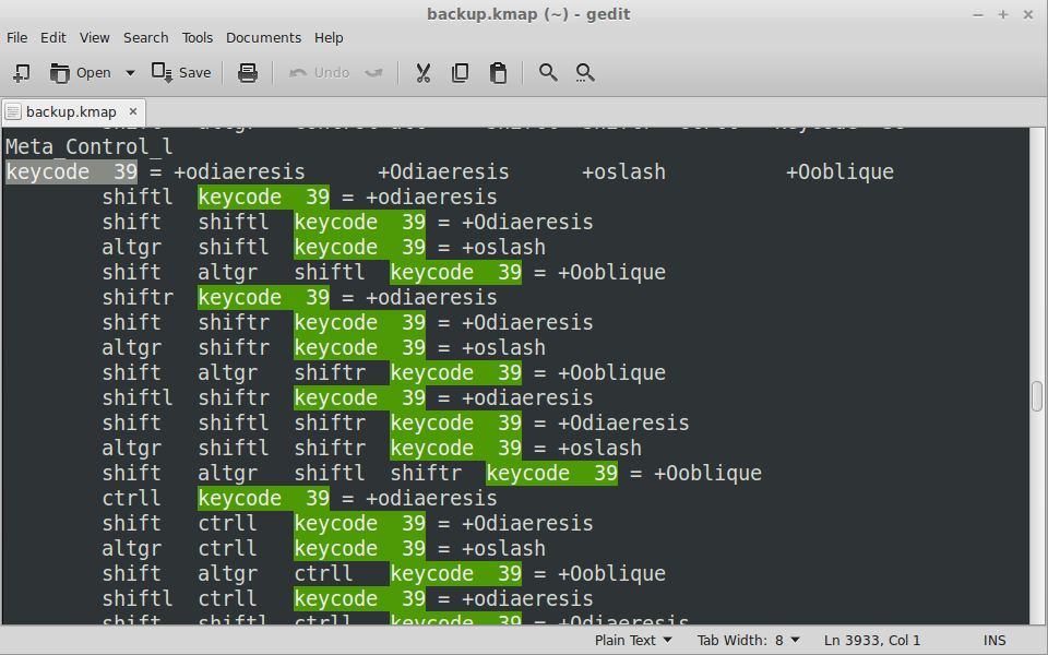
Does that mean that my Swedish keyboard is really sending 'English' keypresses? Let's find out! Remember that we had to tell the computer what layout we were using. This is done in a file called the keymap. Let's look at the keymap my computer uses. It's easily dumped like this:
$ dumpkeys > backup.kmap… and just scroll down to keycode 33 where we'll find 'Ö'... oh crap. That's not right, it says keycode 33 is the letter 'F'?
Oh that's right, the '33' we saw before was hexadecimal, right? And looking at the keymap, the keycodes seems to be in decimal. So we should really be looking at keycode 51 since 0x33 = d51 … but that's not correct either!
These values does not match neither the Swedish nor the American layout, so there is obviously something else happening here.
The scancode sent over USB does actually get converted before we even get to think about the keyboard layout. If we look at the table on this page again, we can see that the keycodes 33 = 'f' and 51 = ',' match the values in column labeled 'Set 1' (just remember to convert to hex first…). Now that we know what to look for, we can see that our USB scancode '0x33' maps to 0x27' in 'Set 1'. So remembering to convert to decimal, we should really be looking for keycode 39 in our keymap. Let's see if we are correct this time.
That looks a lot better! Now it says that keycode 39 should be interpreted as an O with diaeresis - which is just a fancy way of saying 'Ö' :)
So to summarize what happens when I type an 'Ö' on my Swedish keyboard:
- The keyboard sends USB scancode '0x33' to the computer
- The generic USB keyboard driver converts this scancode to a 'Type 1' scancode (39)
- The Type 1 keycode is found in the keymap file and interpreted as me pressing the 'Ö' key
From the keymap and the table we can also see that capital letters and special characters are deduced from the modifier keys, which are sent as separate keypresses. More info on how this is configured can be found on http://linux.die.net/man/5/keymaps.
-
Reverse Engineering the Keyboard, Part II
02/12/2015 at 19:15 • 0 commentsSo I got another package in the mail today, and this little guy was inside!
![]()
This was a purchase from the local eBay branch Tradera, and as you can see it suffers from a damaged display connection. Other than that, it seems to boot just fine.
-'But RasmusB, you already bought an Ericsson MC218, and that one even works! Why did you buy this piece of junk?'
The answer is simple - I live in Sweden, and I want to be able to type Swedish characters on my handheld. This unit has the Scandinavian layout, as can be seen here:
![]()
The Å, Ä and Ö keys are the important ones if you are writing Swedish. The other two characters (Æ, Ø) are not used in Swedish, but since they're on the keyboard I'll probably implement them as well. I'll make my USB keyboard controller work with both the English and Scandinavian layout so it's useful to non-scandinavians as well.
So now I'm just waiting for my breakout PCBs so I can start hacking on these keyboards (pun not intended).
-
Hunting for a Display
02/06/2015 at 22:03 • 3 commentsCurrent project status:
- My ATmega32U4 board has arrived. I opted for the OLIMEXINO-32U4 because it happened to be cheap. It also had some extra goodies on board which made the decision easy.
- My keyboard breakout PCB:s are also on their way from OSHpark. Should be here in two weeks.
- ... but as it turns out, the connector is not. It is on backorder with ETA 7 weeks... :( I did some digging in my parts bin and found something that should work for the first prototype at least, I'll show you a picture once I have got it working.
Now for tonights topic: finding a replacement LCD.
I have had the opportunity to play around with the working Psion units during the last days. The keyboard is slightly more "rubbery" than I remembered it, but I'm still in love with the form factor. :) The biggest surprise was how lousy the display is! A lot has happened in the last 15 years to say the least. The resolution is actually still OK - the OS is well optimized for this screen - but the contrast is horrible to put it bluntly. It gets even worse if you are trying to use it in a dark room with the backlight on.
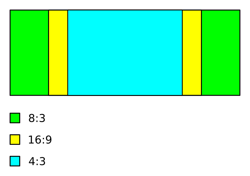
My original plan was to try to get some more life out of the original LCD, but now I don't think it will be worth the trouble. Which is a shame, since it is a really power efficient design. Another problem is the weird aspect ratio of the original display (8:3). It is very hard to find a screen that utilizes the available space as much as possible.
This picture illustrates the problem. The narrower the aspect ratio, the smaller the screen I can fit in the lid.
![]()
In the spirit of power efficiency, I first looked REALLY hard for some kind of passive display such as e-ink, or memory LCD. These look absolutely gorgeous, has excellent readability even in sunlight and hardly consumes any power at all. (See some examples here). However, most passive displays tends to be closer to 4:3 than 8:3. Simply put, I could only fit a display that is roughly half as wide as the original, or try to live with a really small screen.
For a while I even considered fitting two 4:3 displays next to each other, but I don't really see the benefit of having a dual-head setup on a handheld.
So 4:3 is out and passive display technology is out. That leaves us with a traditional 16:9 LCD module.
So how big of an 16:9 display can we fit?
The Active Area (AA for short) of the original display is about 134x50 mm, but the slot cutout in the lid is 60 mm high. Also, the bottom labels could be cut off, leaving us with a possible screen height of up to 65 mm! This means that we can fit a display with an AA of 5.0" provided the bezels are thin enough.
I stumbled upon a promising candidate on aliexpress. A 5.0" OLED screen with minimal bezels, built-in capacitive touchscreen and it's only 1mm thick (including the double sided mounting tape on the back). The thickness (thinness?) is a great bonus since I will need some flexibility bringing the FPC screen cable from the lid down to the main board. With a screen 1mm thin, I can fit some adaptors in the lid. Also, the vendor was kind enough to send me an excellent data sheet.
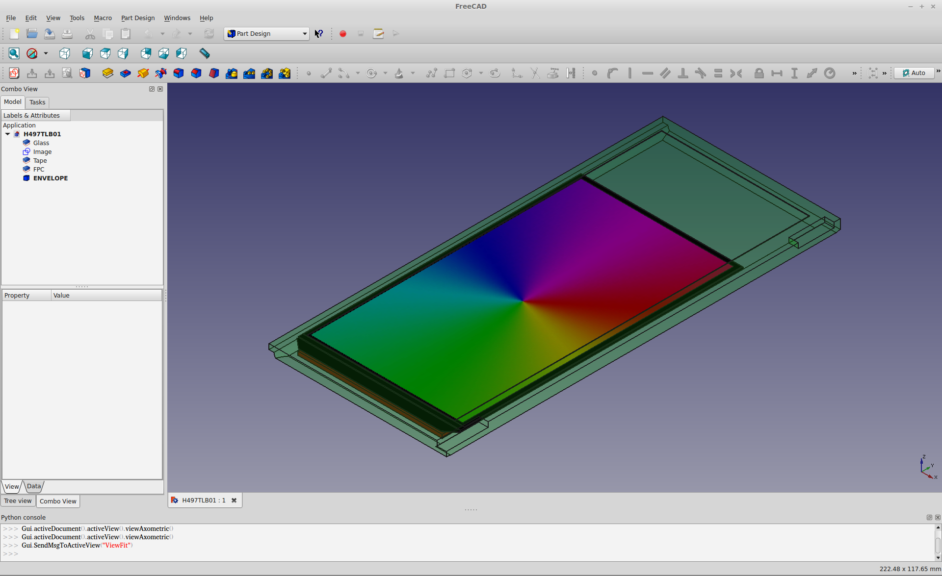
I made a mockup in FreeCAD to see if it would be a decent fit.
![]()
The green, semi-transparant blob is the volume occupied by the old LCD. The black monolith is the OLED under consideration, and it fits in the available space without problem. I would of course have to add some kind of display carrier to stop it from falling out, but that is a later issue. Right now I'm thinking of what to do with the empty space on the sides. Maybe add some additional (small) SPI screens to display system load, time, battery charge and so on... This is not completely unlike the original OS that has the option to show a "clock" bar to the right of the screen.
But before I get that far, there is a bigger issue to tackle - interfacing.
- Almost every modern LCD/OLED module uses either DisplayPort or (more commonly) DSI
- There are still SPI or parallell interface LCD:s available, but they all tend to be smaller than 5", or low resolution
So DSI is the technically superior choice. Also, since it is used in most smartphones these days, there is a large selection of displays in every imaginable size. Even the Raspberry Pi has an DSI connector on board... it's only that it is useless right now since there is no driver for it yet, even though it has been promised for a while now... :(
But there is always a plan B - build a converter! That way, I can use the standard HDMI output of whatever SBC i end up using, and still use a nice screen. I'd rather waste my time on something else though, so for the time being I'm going to plan for using a DSI screen and hope that I'll find some way to drive it in the future... :)
To be continued...
-
Reverse engineering the keyboard, part I
01/30/2015 at 19:15 • 0 commentsThe first part I'm attacking is the keyboard. The keyboard is the reason I want to build a "modernized" Psion, I really like this form factor! The plan is to convert it to a USB keyboard since that will work with any modern computer, but before I can do that I need to figure out how it works.
![]()
While i probably could have reverse engineered the keyboard by measuring on the connector and pressing keys, I thought it would be easier to disassemble it completely and study the PCB inside - especially since the keyboard connector is pretty small (0.5mm pitch). So I started with popping off the keys and removing the rubber pad. All the keys went into the ultrasonic cleaner for a few minutes (they weren't that dirty, but since it already was in pieces...). The rubber pad and PCB weren't cleaned in liquid, since I might have damaged the conductive carbon surfaces.
![]()
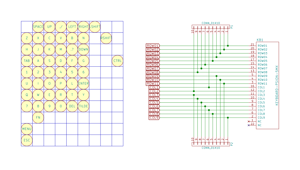
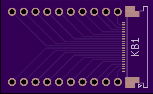
Working my way through the PCB with the help of some macro shots and my multimeter, I eventually ended up with the matrix configuration. Some of the function keys get special treatment, I'm guessing to avoid ghosting issues. Otherwise they could have gotten away with having a 6x8 matrix for the 53 keys, this way they could have saved 6 GPIO pins on the CPU. I also designed a quick breakout board to allow me to start writing the firmware for my keyboard.
Speaking of number of pins - the eagle-eyed amongst you will have noticed that pins 1 and 22 are unconnected in the schematic below. The reason is that the keyboard uses 20 pins, but the FPC cable is wide enough for 22 pins! If I would have designed my breakout board with a 20 pin connector, the cable would have been too wide to fit... I think an earlier design might have used some kind of ground loop on the two outermost pins to prevent EMC issues, and it was removed for some reason later in the design process.
![]()
![]()
The PCB was ordered from OSHpark, but there is plenty of other stuff to do while waiting for it to arrive... :)
-
Dissecting the first patient
01/30/2015 at 18:24 • 0 commentsTime to get to work!
As I wrote in the last log entry, I have two Psion units that I'm going to disasseble. One won't power up but is in good condition mechanically, and the other won't open but powers on correctly. I chose to start by taking the unit that wouldn't open apart. The goal was to at least extract the keyboard and learn something about the internal design.
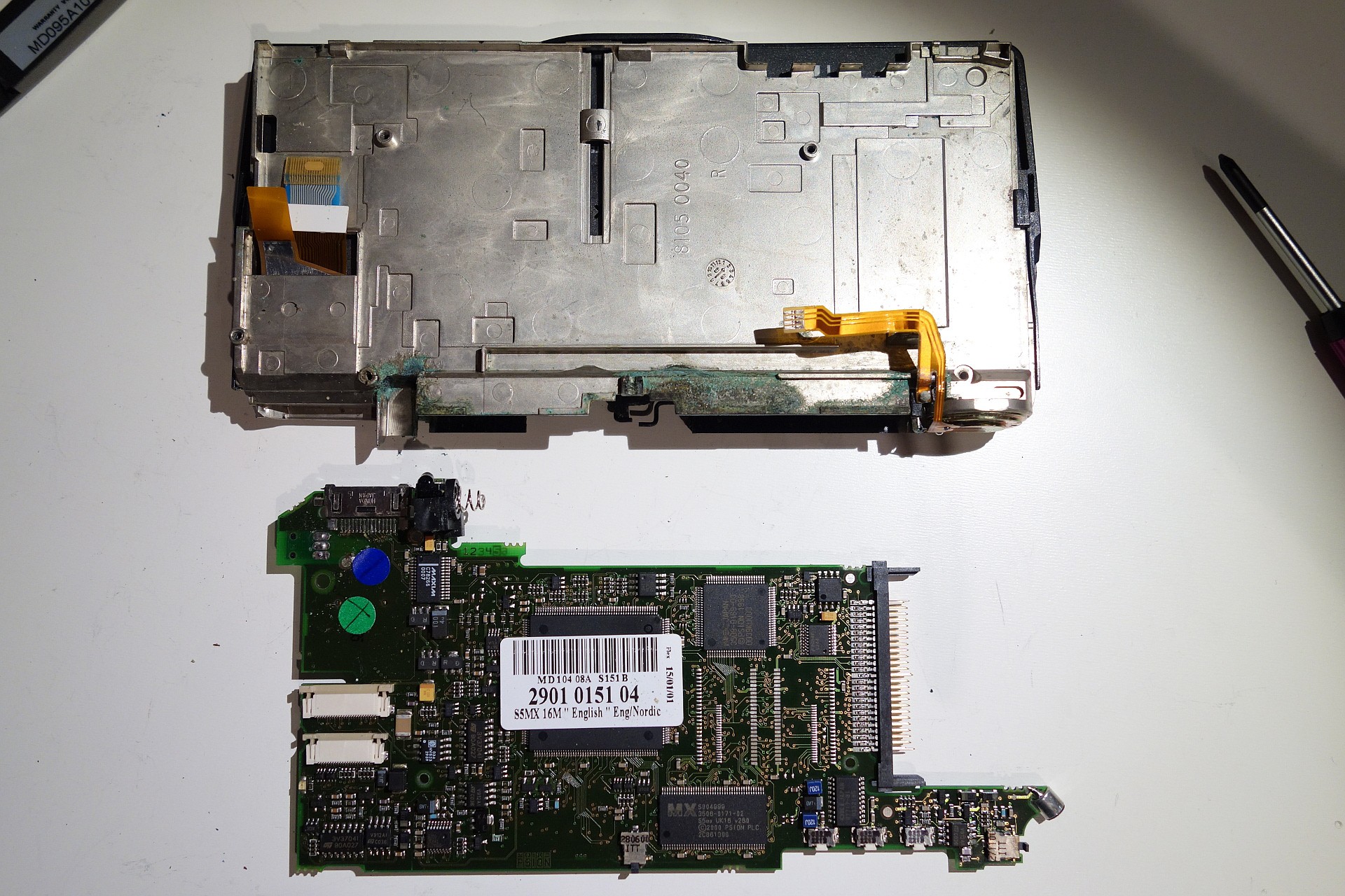
I had already noticed some discoloration from leaking batteries in the battery compartment, but as I opened the unit closer I found out that it was worse than expected. The battery bay had cracked on the inside, and the leaking battery juices had crept up to the main circuit board. Oops.
![]()
Even the plastic had been attacked by the battery gunk. The metallized plastic (top of image) had been attacked to the point where the metal had dissolved completely.
![]()
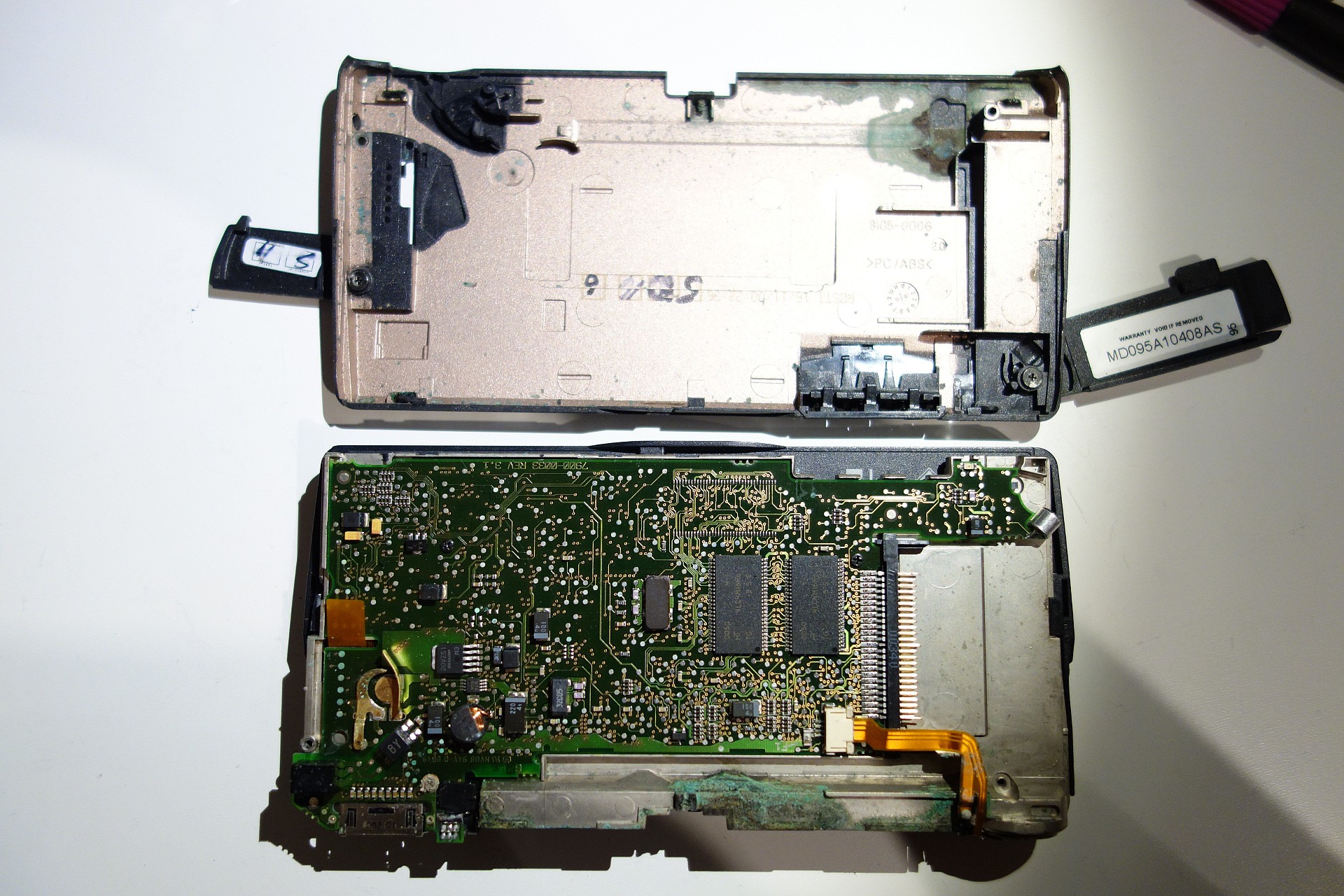
Luckily, the circuit board itself seemed mostly unaffected though. In the lower left corner some corrosion can be seen on the exposed test points, but apart from that the board looks fine! From this point, getting the main board out was just a matter of removing three Philips screws and disconnecting the three FFC cables for the keyboard, LCD and speaker.
![]()
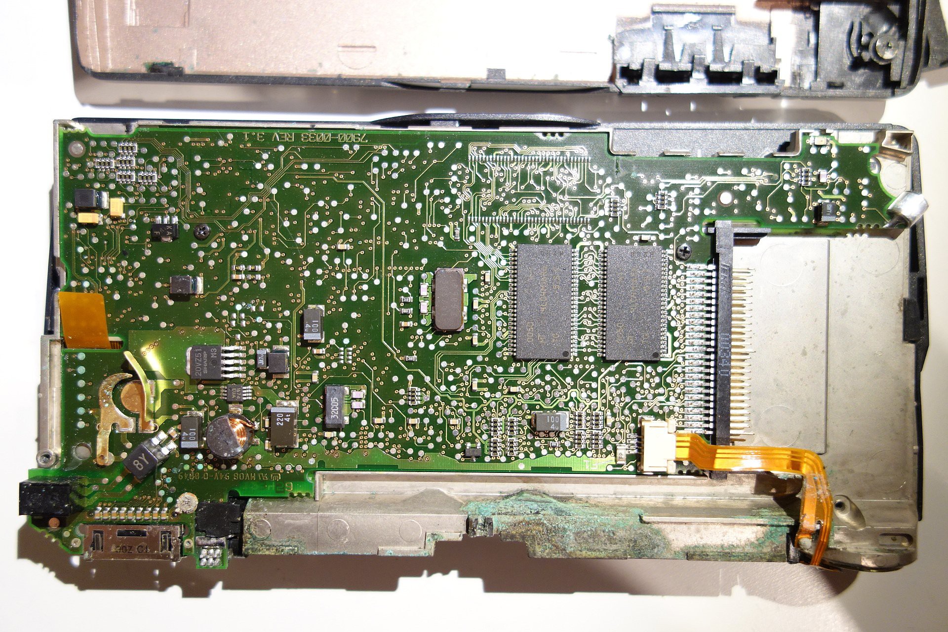
So this is what I have to work with. I have this crazy idea of keeping the CF bay intact, to be able to build some kind of expansion boards later on (using the CF connector with a custom pinout). That will of course depend on how compact I can make the new main board. The old board is 1mm thick and has 6 layers. Mechanically, it is a tigher fit than I had expected. The older Series 5 model had a daughter board installed, (see https://www.ifixit.com/Teardown/Psion+5+Teardown/1650 ) so I had expected some more room. I might be fooling myself though since it is very hard to estimate the amount of "air" inside the chassis.
Right now, I'm playing with the idea to make a cast of the inside of the chassis (using alginate or something similar) to find out the exact volume I can use. Ideas are appriciated :)
-
The donors have arrived
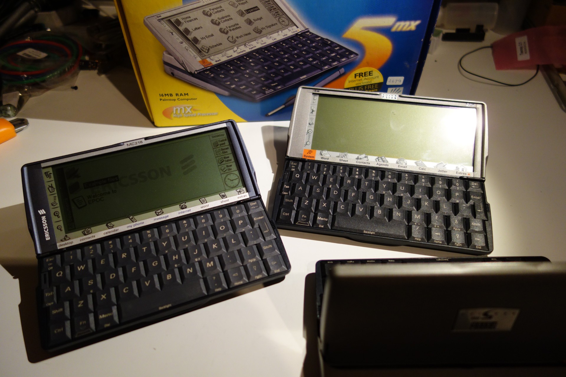
01/28/2015 at 16:57 • 0 commentsToday I got my donor units! I purchased a package of two Psion 5mx handhelds - one of them does not power on, but is in good shape mechanically. The other powers up, but it doesn't open very well. The cause seems to be that is has been dropped hard, the battery compartment i beat up. It also seems that the batteries started leaking since there is evidence of corrosion (green battery terminals and discolored plastic).
The plan is to start with the mechanically broken unit and remove the keyboard. This will be converted to USB, but first I need to reverse engineer the circuit board.
I also got a Ericsson MC218, which is a rebranded 5mx. This is in very nice condition, and will be kept as is for nostalgic reasons. :) I noticed some signs of vertical banding on the display though (a design defect on these units), but I'll fix that at a later date.
![]()
![]()
 The keymap seems to be working now. If you are feeling brave, you can do the same with an Arduino Leonardo and a Psion keyboard.