Close
0%
0%

Servicing and Upgrading a Harbor Freight Mini Mill

Years ago, I converted a Harbor Freight mini mill to a CNC using a CNCFusion kit and stepper controllers from HobbyCNC. Time to fix it!

Similar projects worth following
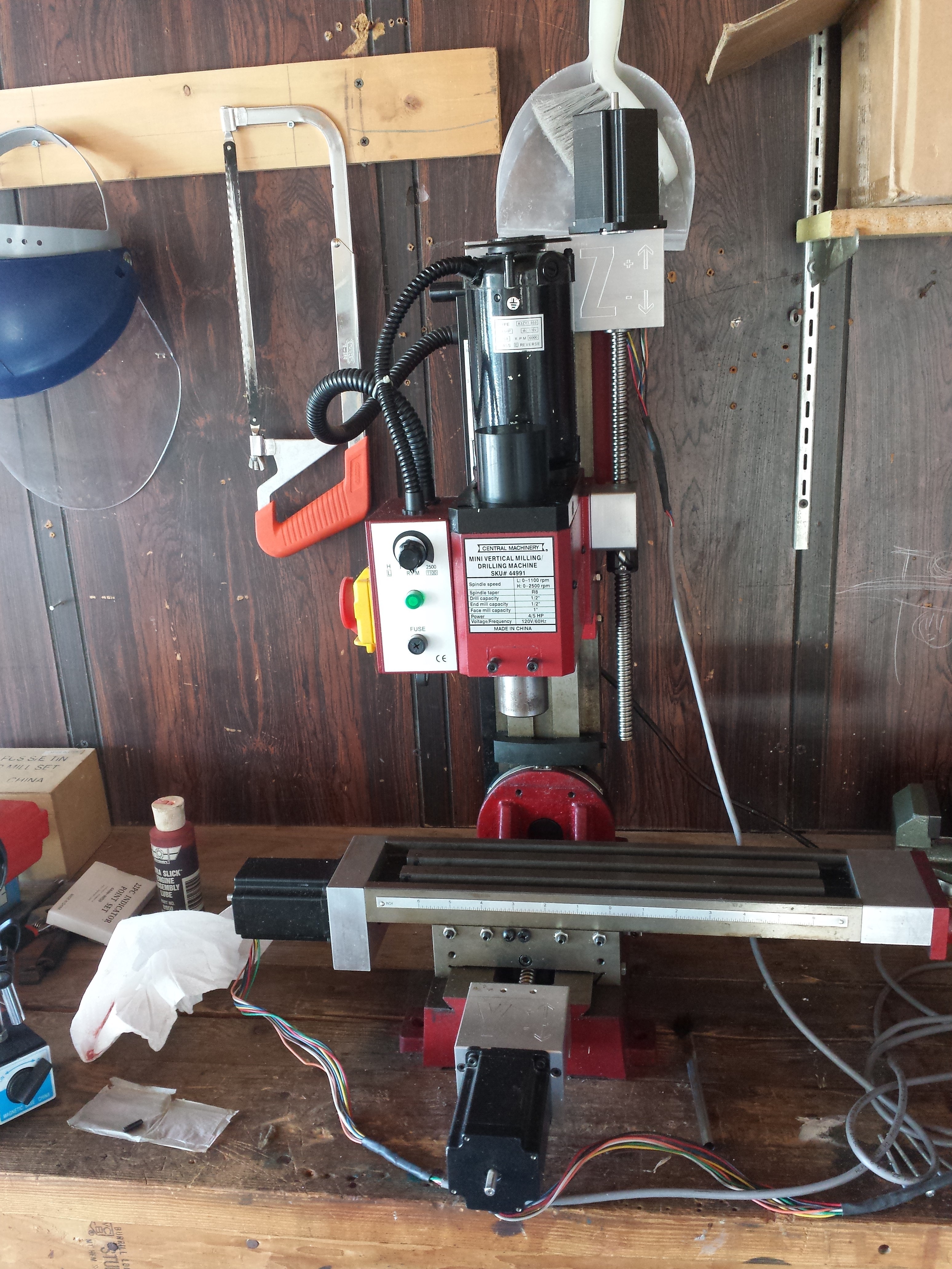
Several years ago, I converted a Harbor Freight mini mill to a CNC using a CNCFusion kit and stepper controllers from HobbyCNC. It's been sitting in storage for a few years now and is in need of a service and upgrade. Since it was originally a manual mill, it lacks many of the bells and whistles of proper VMC. This project aims to rectify some of these deficiencies.

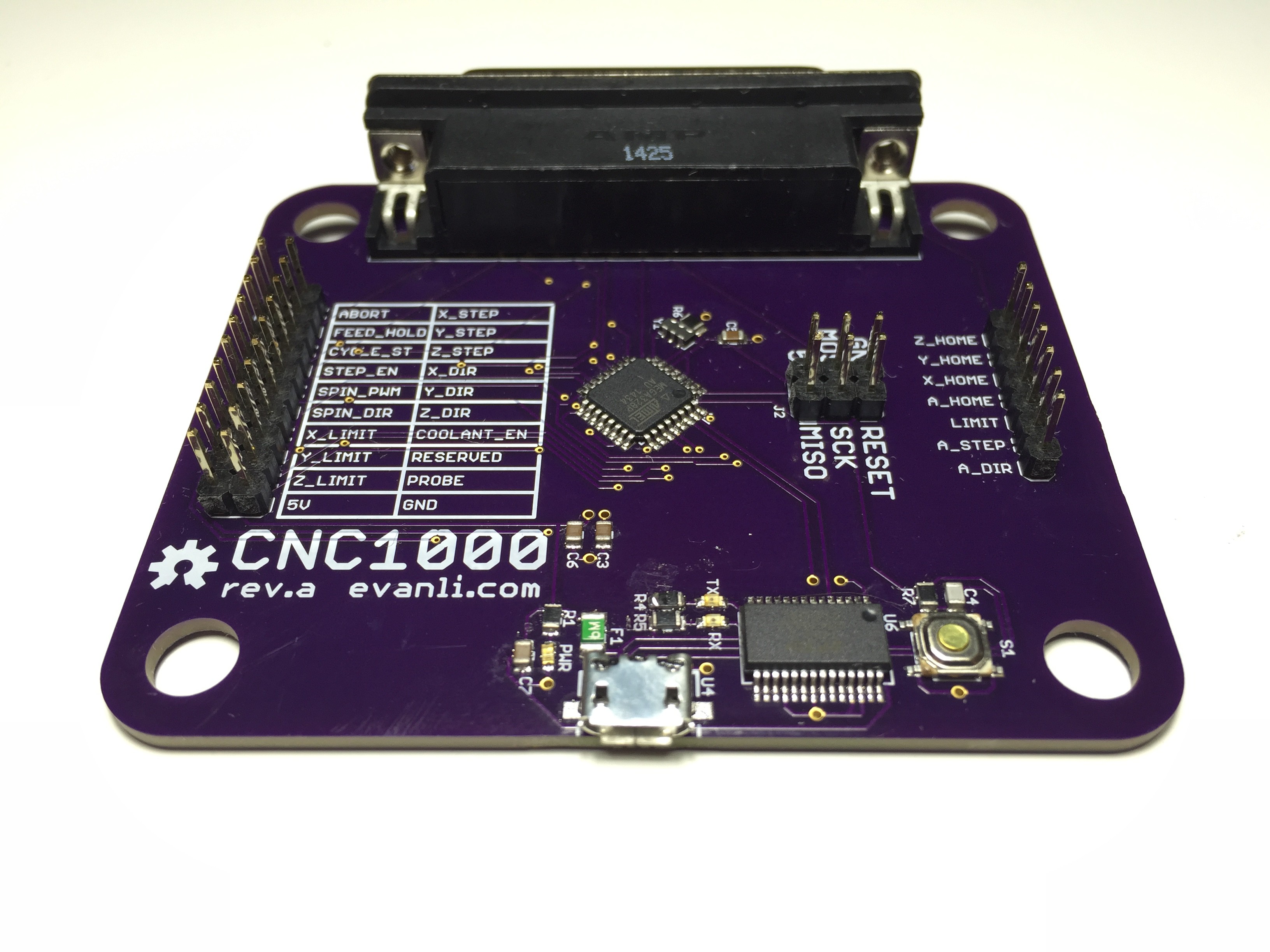
The plan is to replace the parallel port interface on the stepper driver with a microcontroller running GRBL. The mill can than be run from a USB interface on any computer rather than a increasingly rare parallel port. Also planned are some incremental upgrades to the hardware on the mill, such as spindle control, and a flood coolant system.

  • 1 × ATMega328P Microprocessors, Microcontrollers, DSPs / ARM, RISC-Based Microcontrollers
  • 1 × Acer TravelMate 2420 laptop, x86, intel, celeron m

  • The Plan Changed

    Evan Li11/30/2016 at 07:31 0 comments

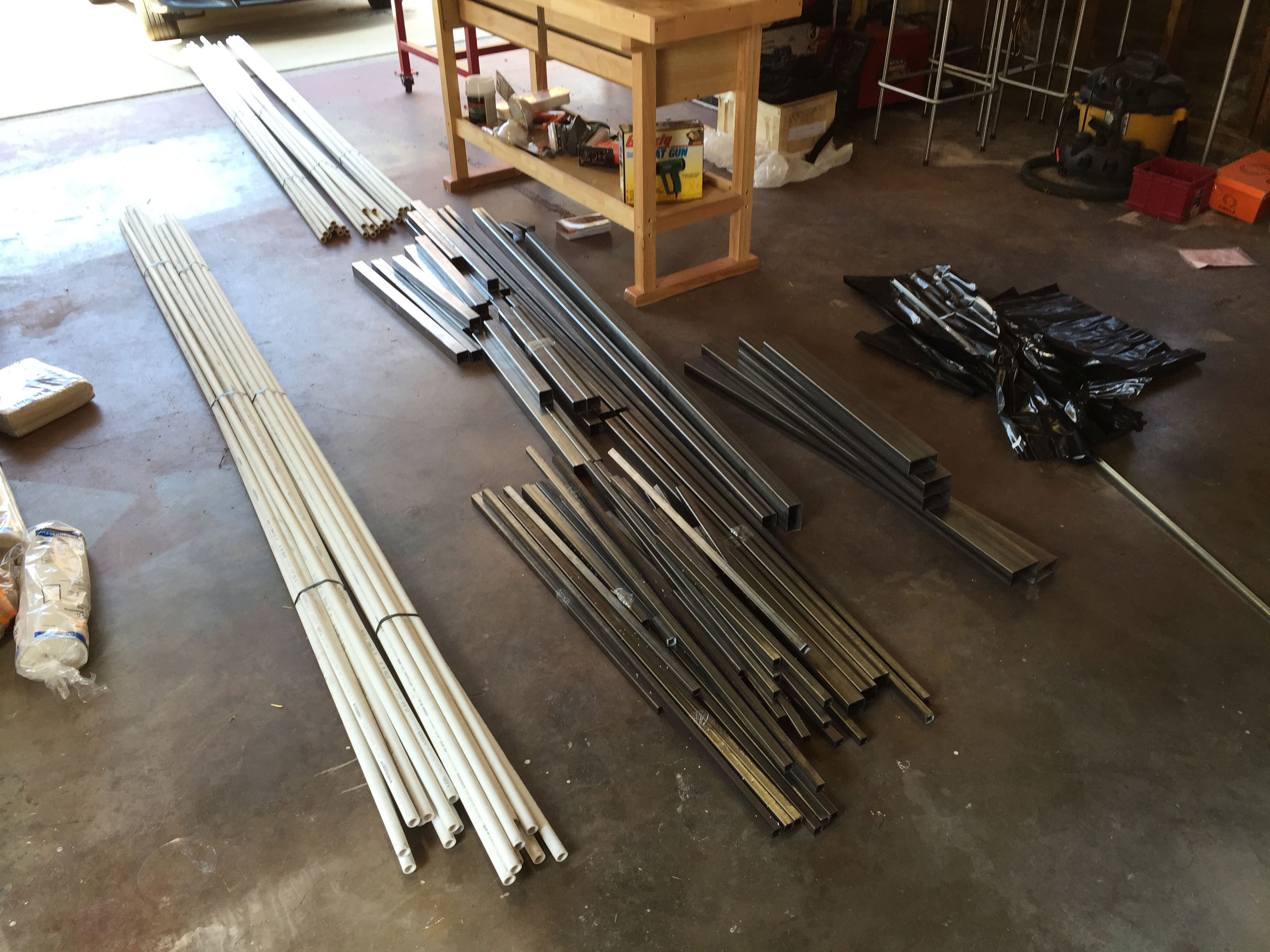
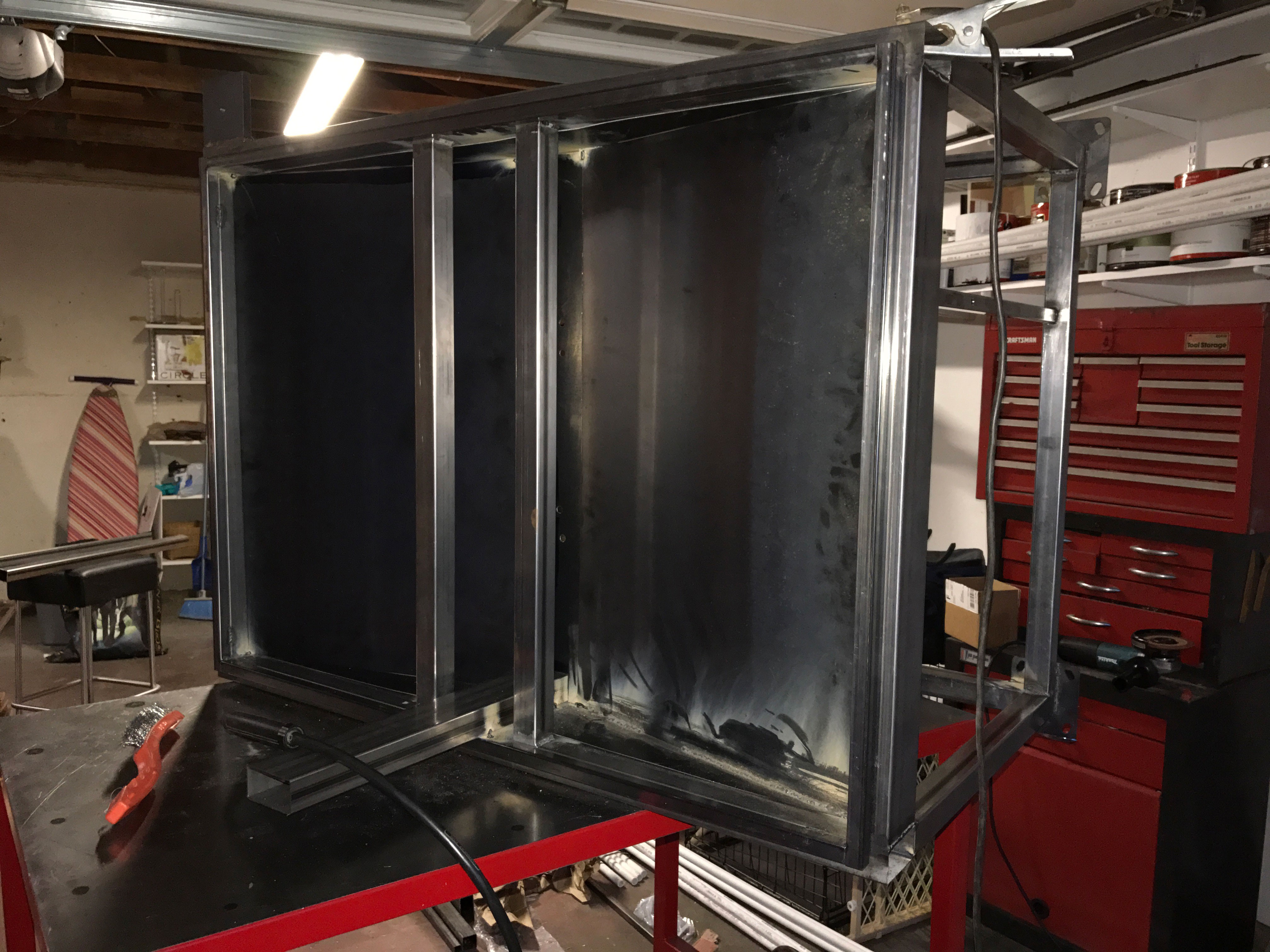
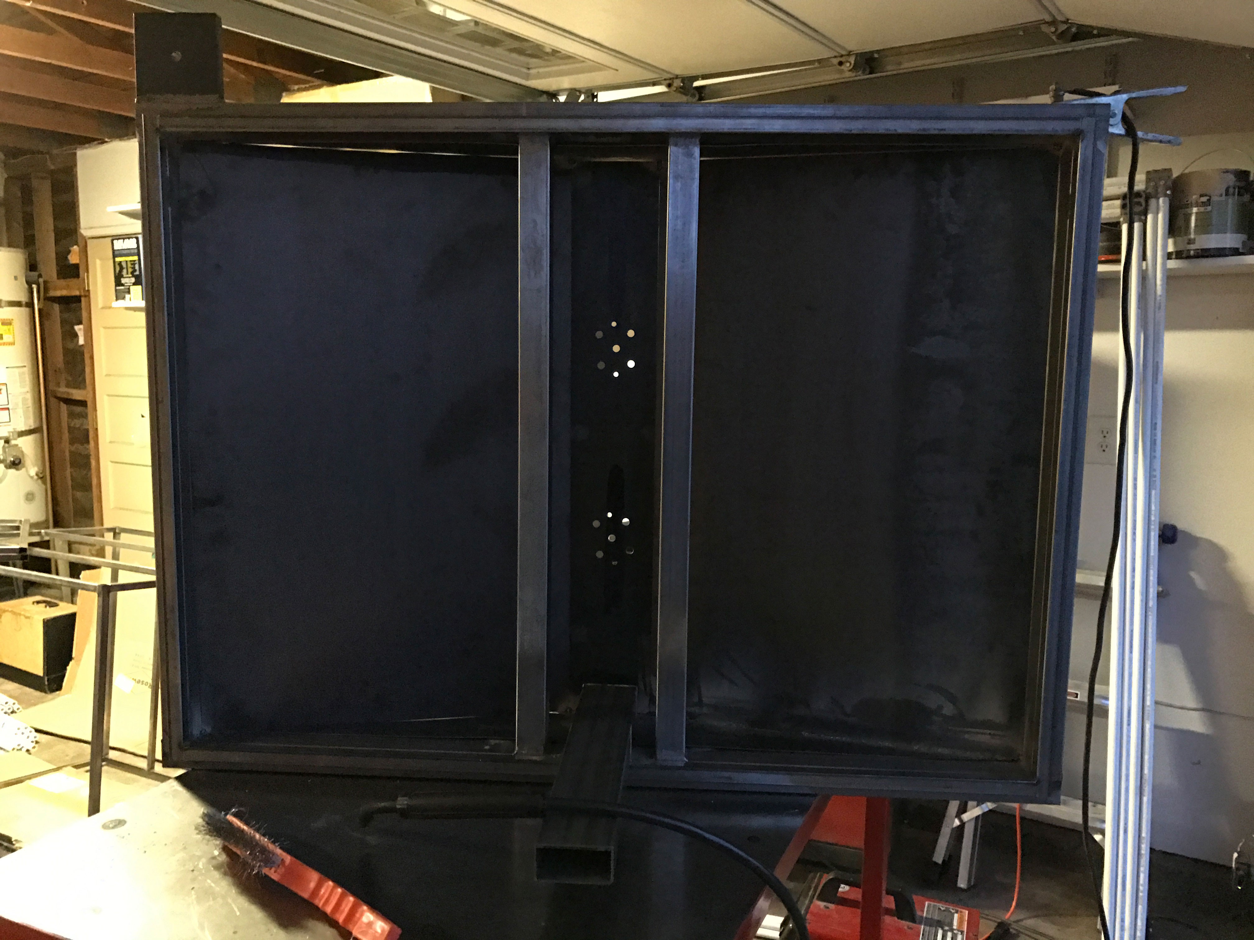
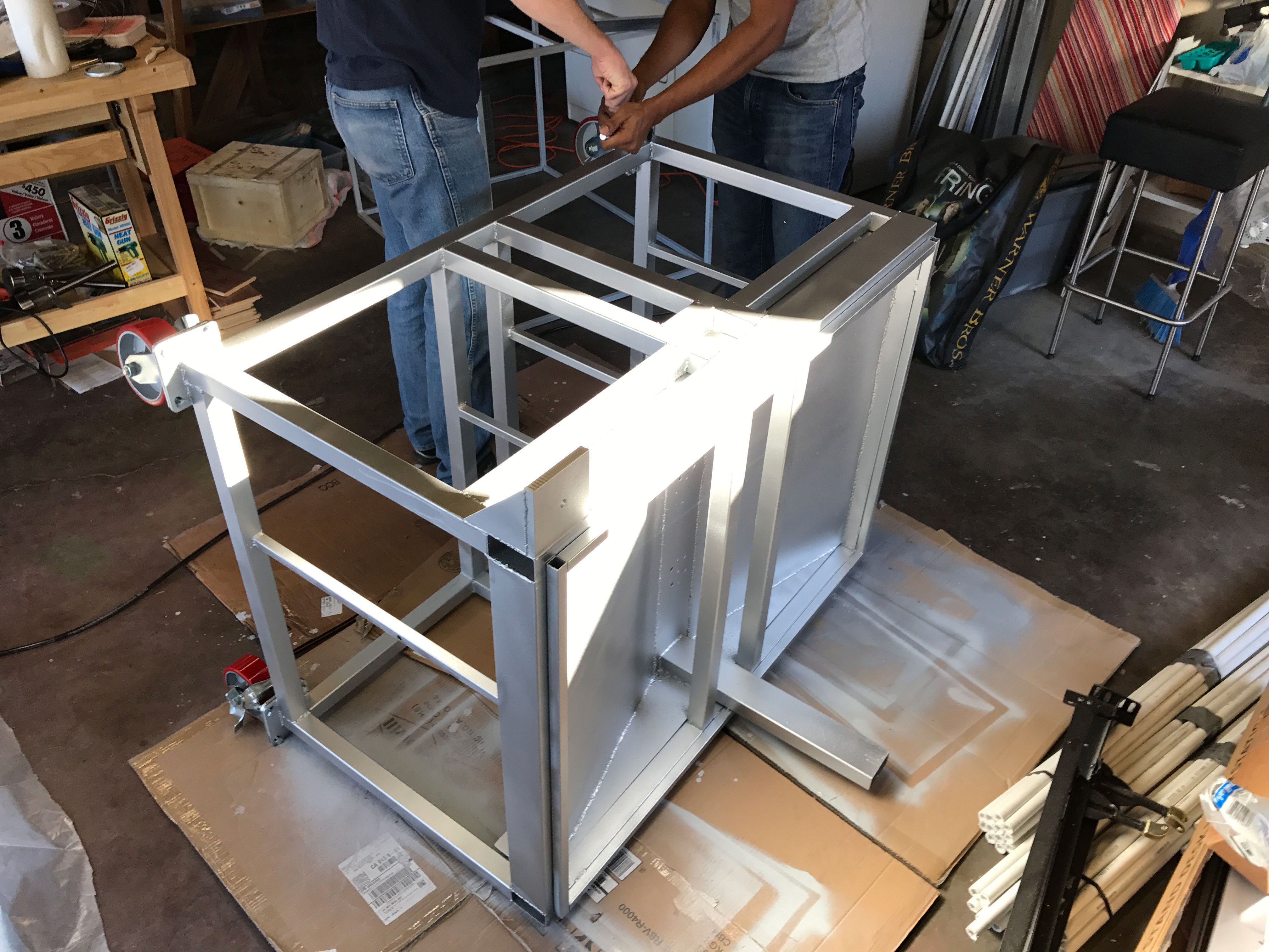
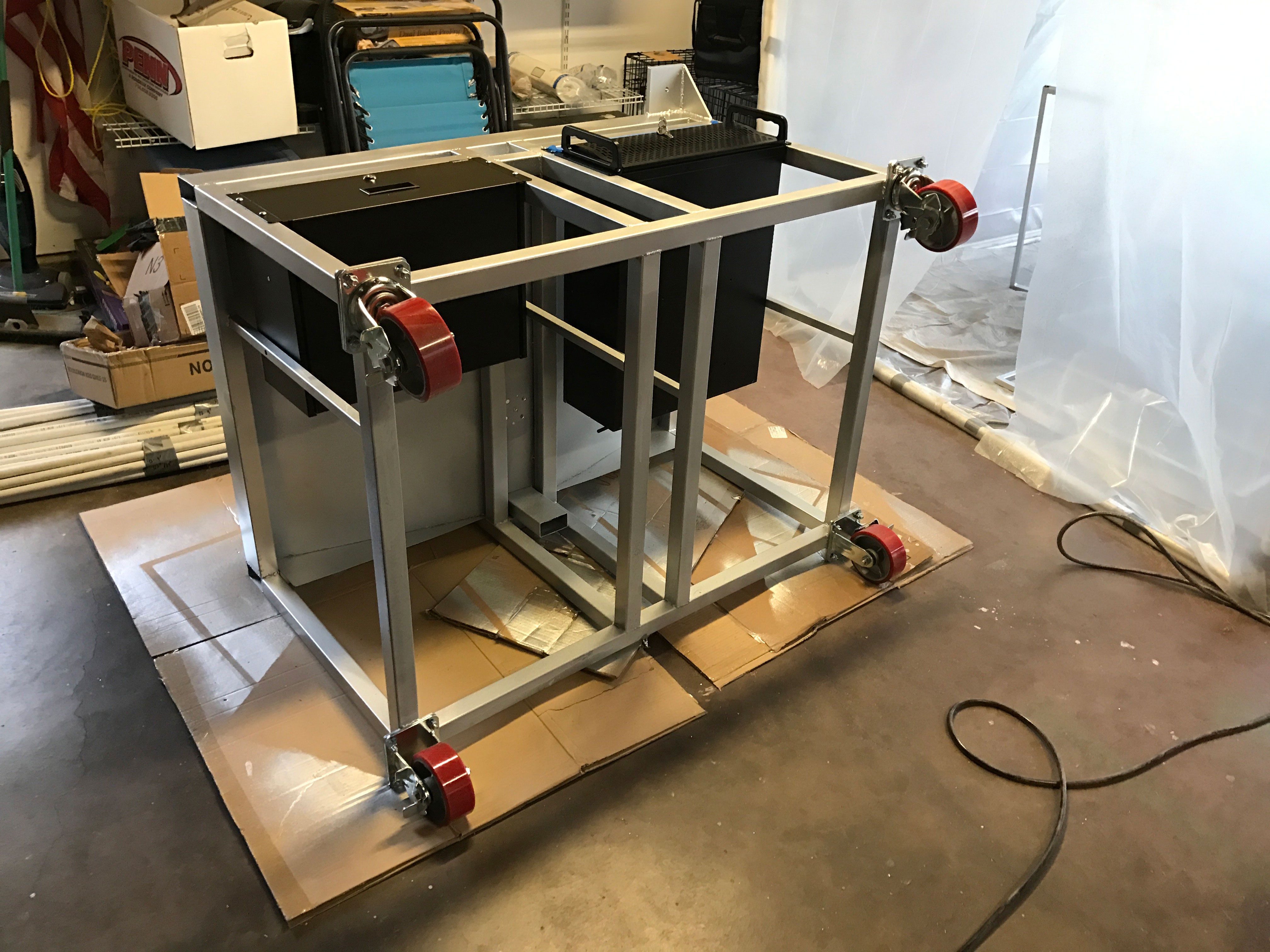
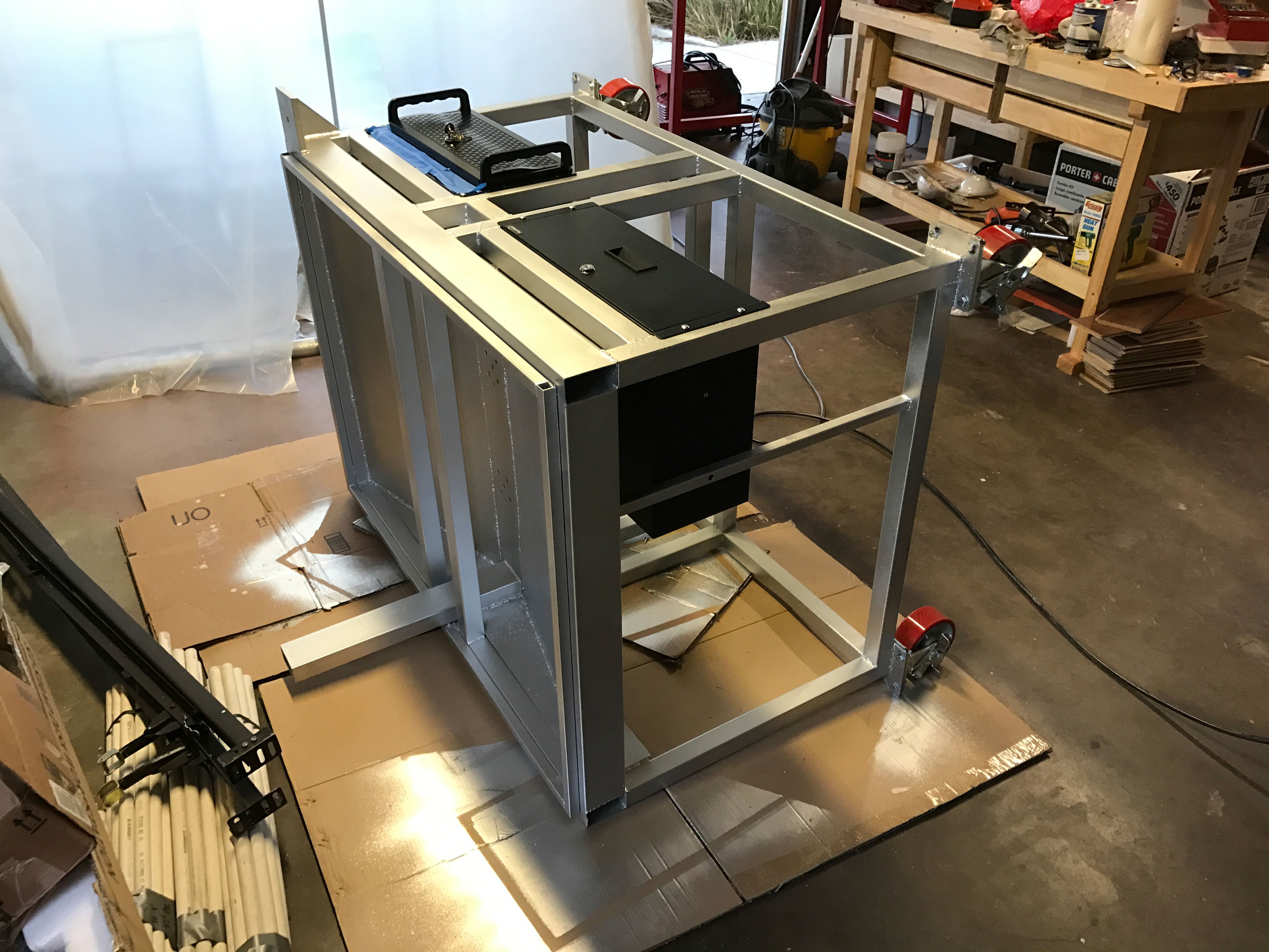
    The initial plan to just refurbish the mill was scrapped, in it's place is a new plan to build the mill into a more robust VMC type tool. The new setup has a flood coolant system, and more integrated electronics. The plans for the enclosure/stand will be made available soon. The following is a brief log on the fabrication of the enclosure/stand.

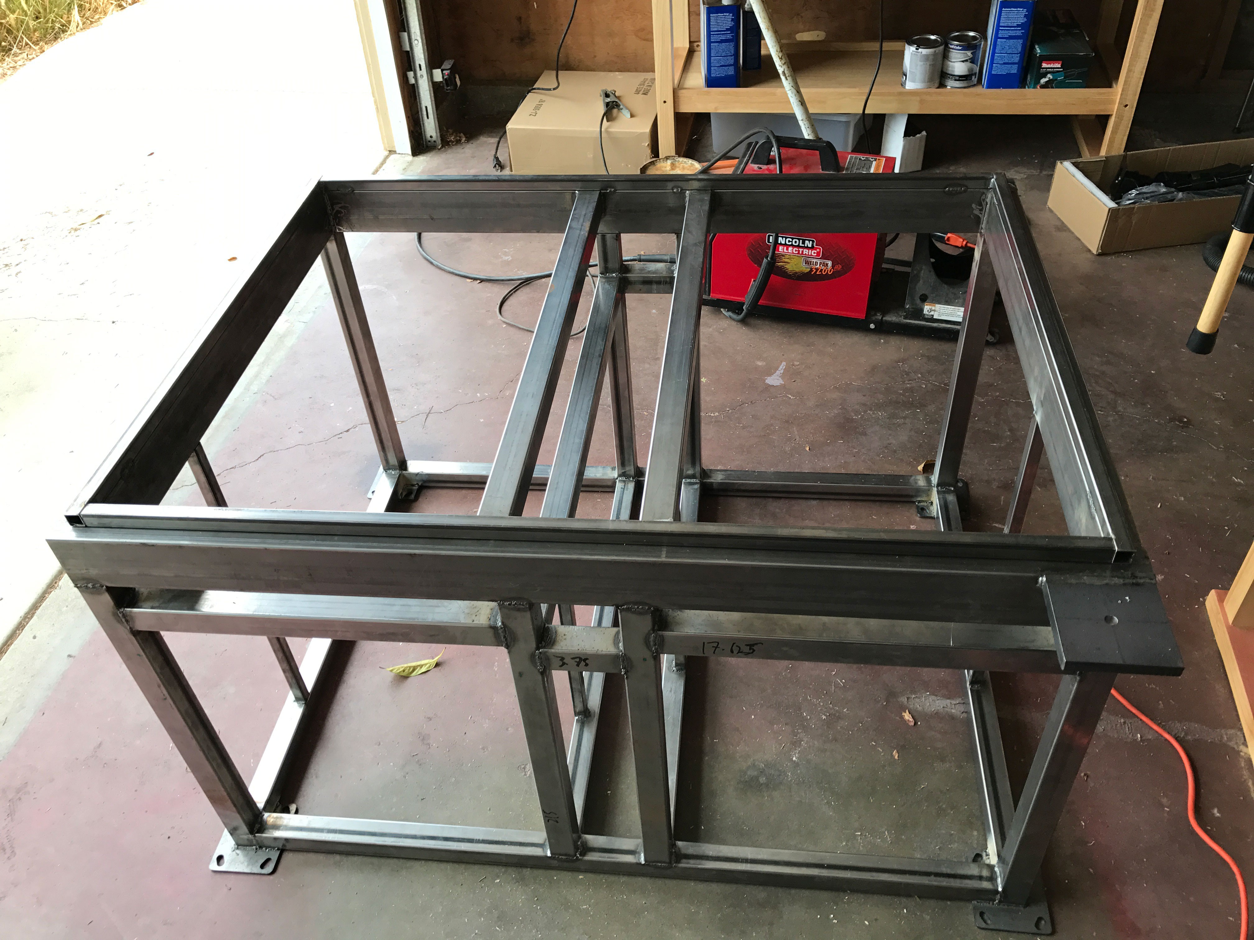
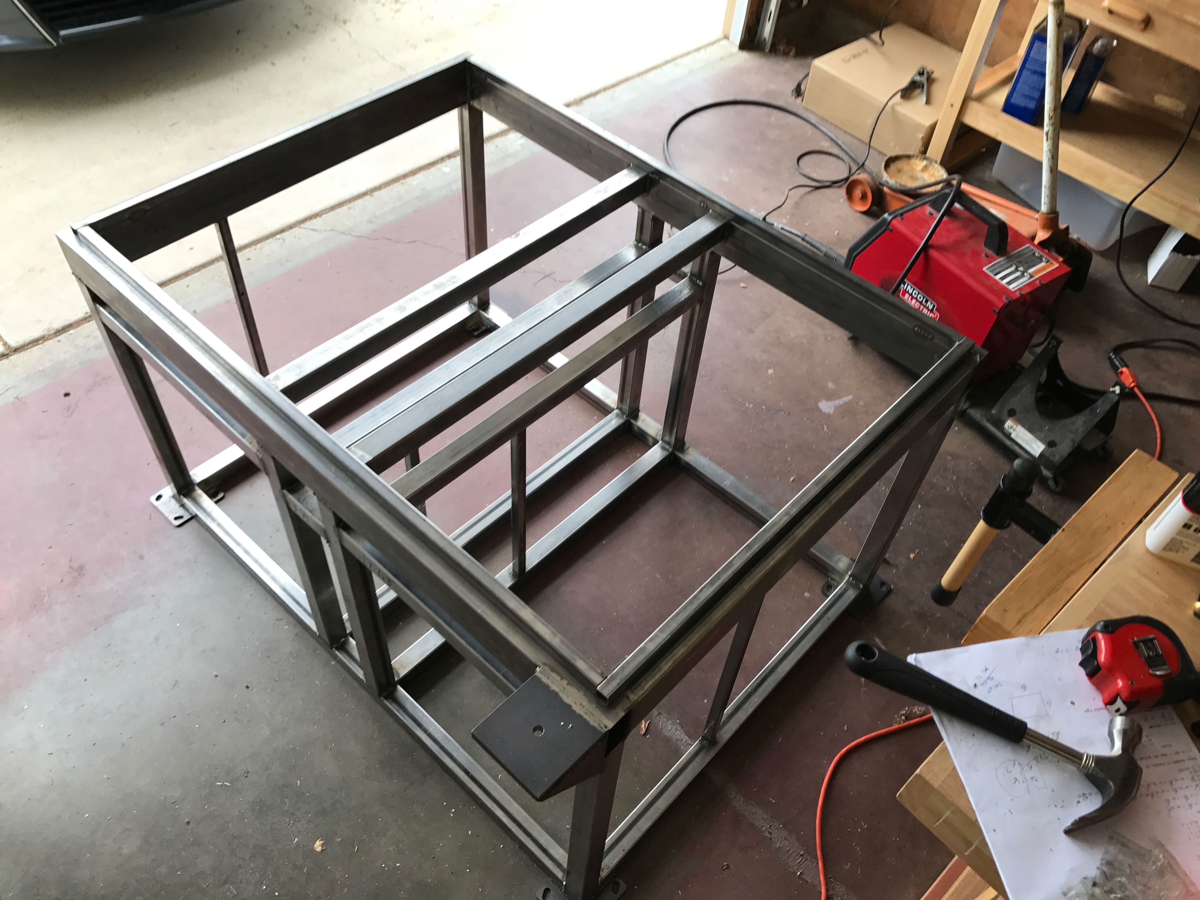
    The mill enclosure/stand is made from plain steel tubing welded together.

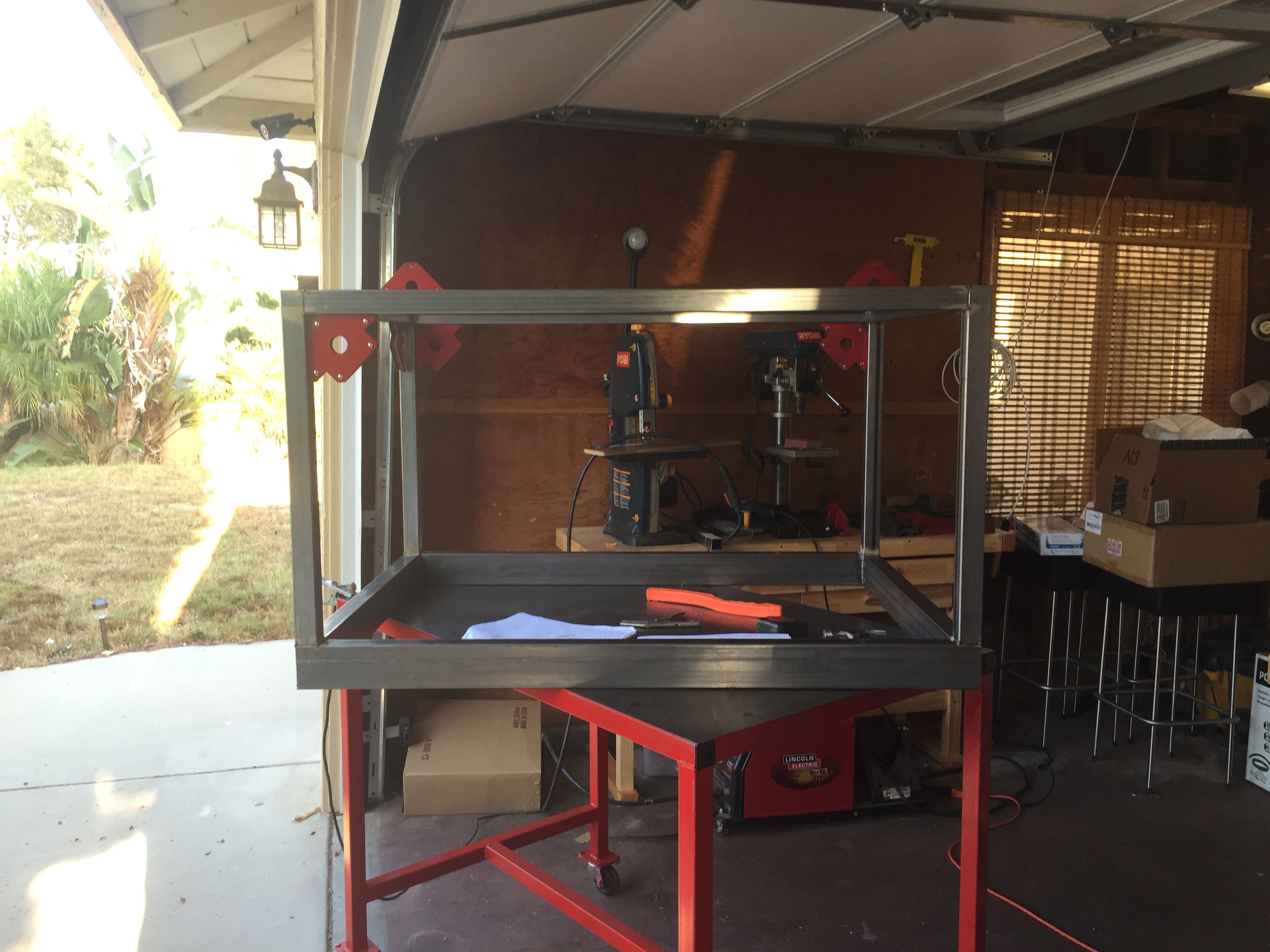
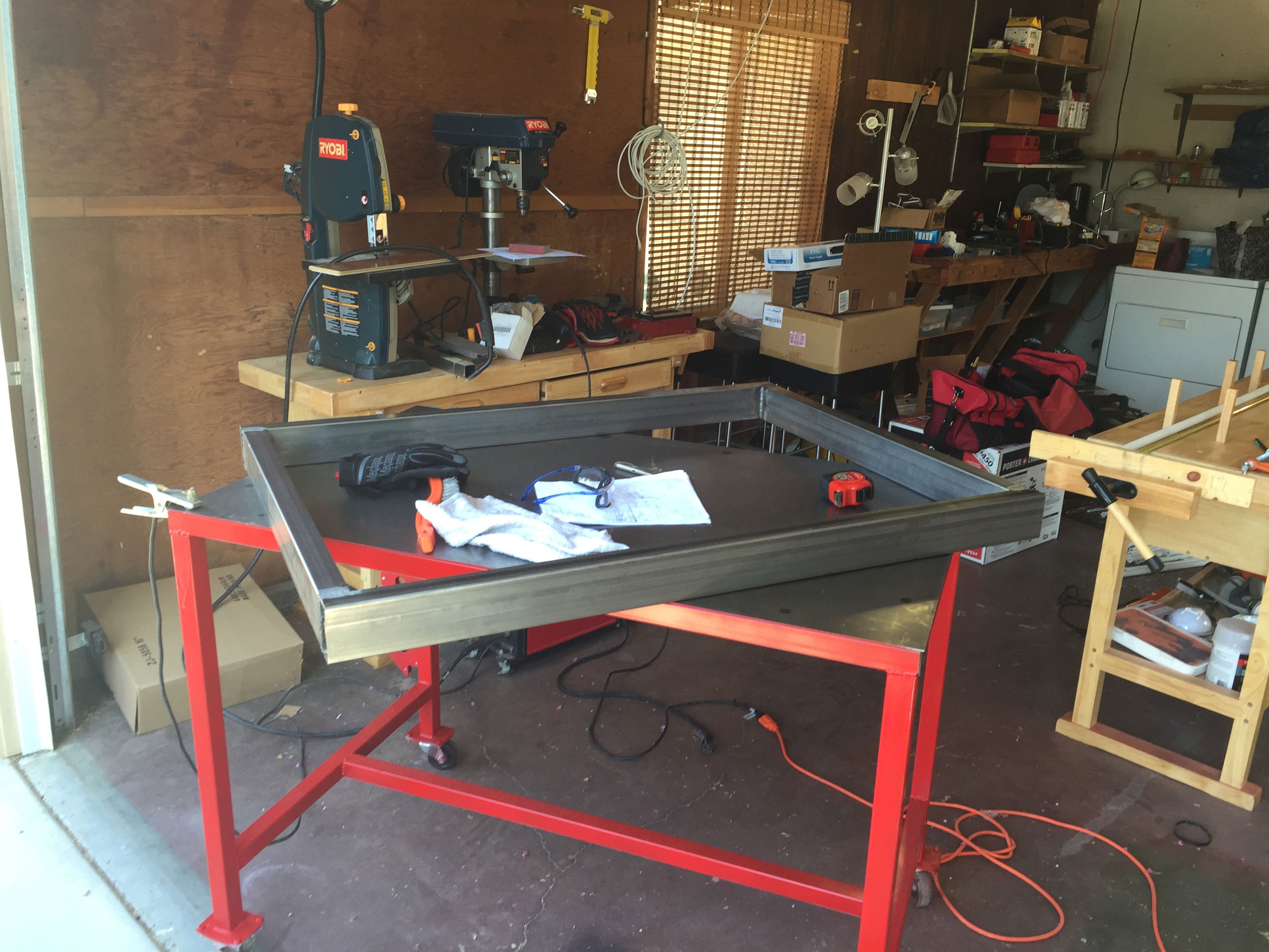
    The tubing was squared up using magnetic squares and welded with flux core steel wire. Didn't have a gas bottle for proper MIG welding.

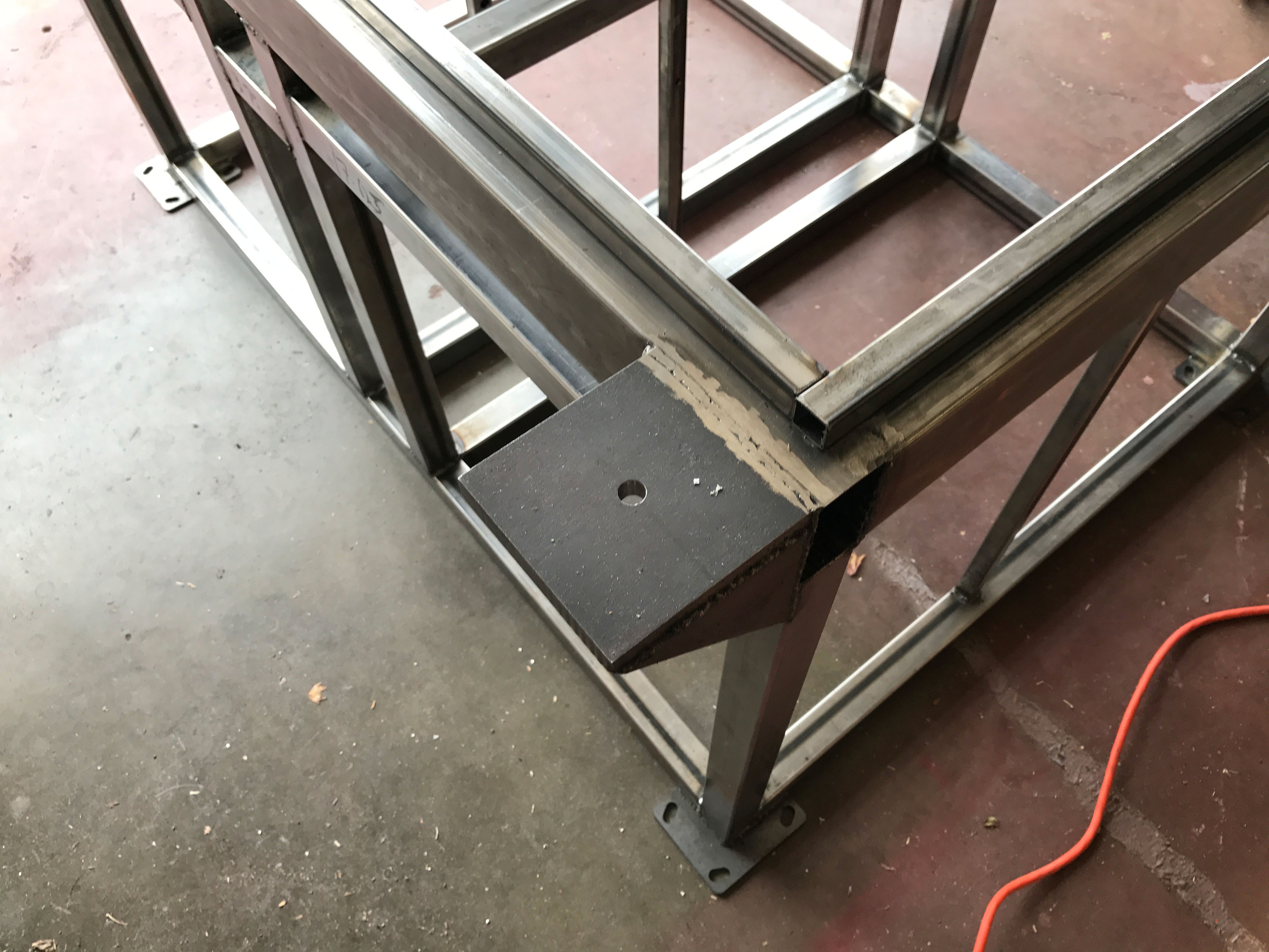
    This is the upper section of the stand. Its made from 1.5" x 3" 16ga steel rectangular tubing.

    A plate was welded to the upper section as a mount for the display and keyboard arms.

    The completed stand before coating.

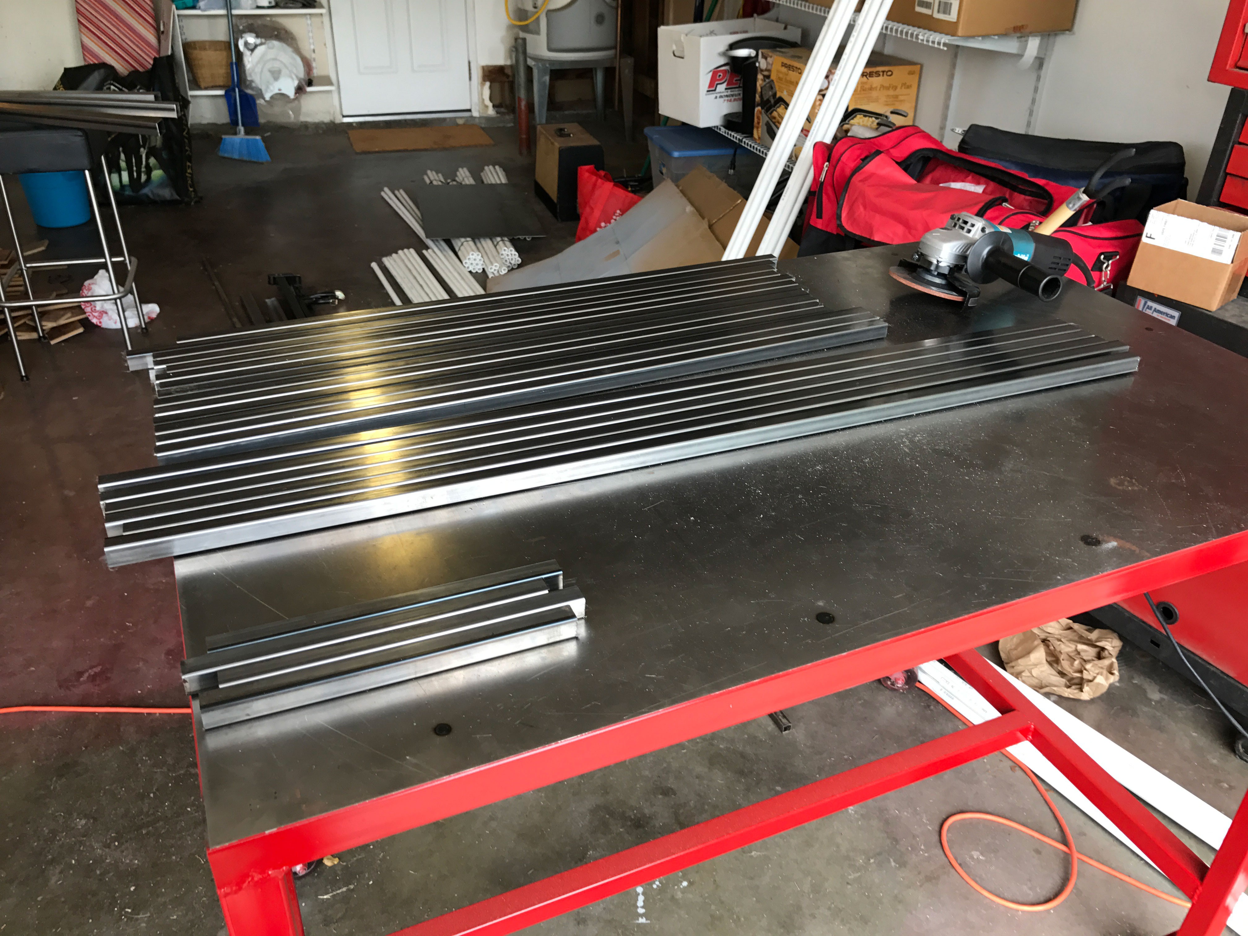
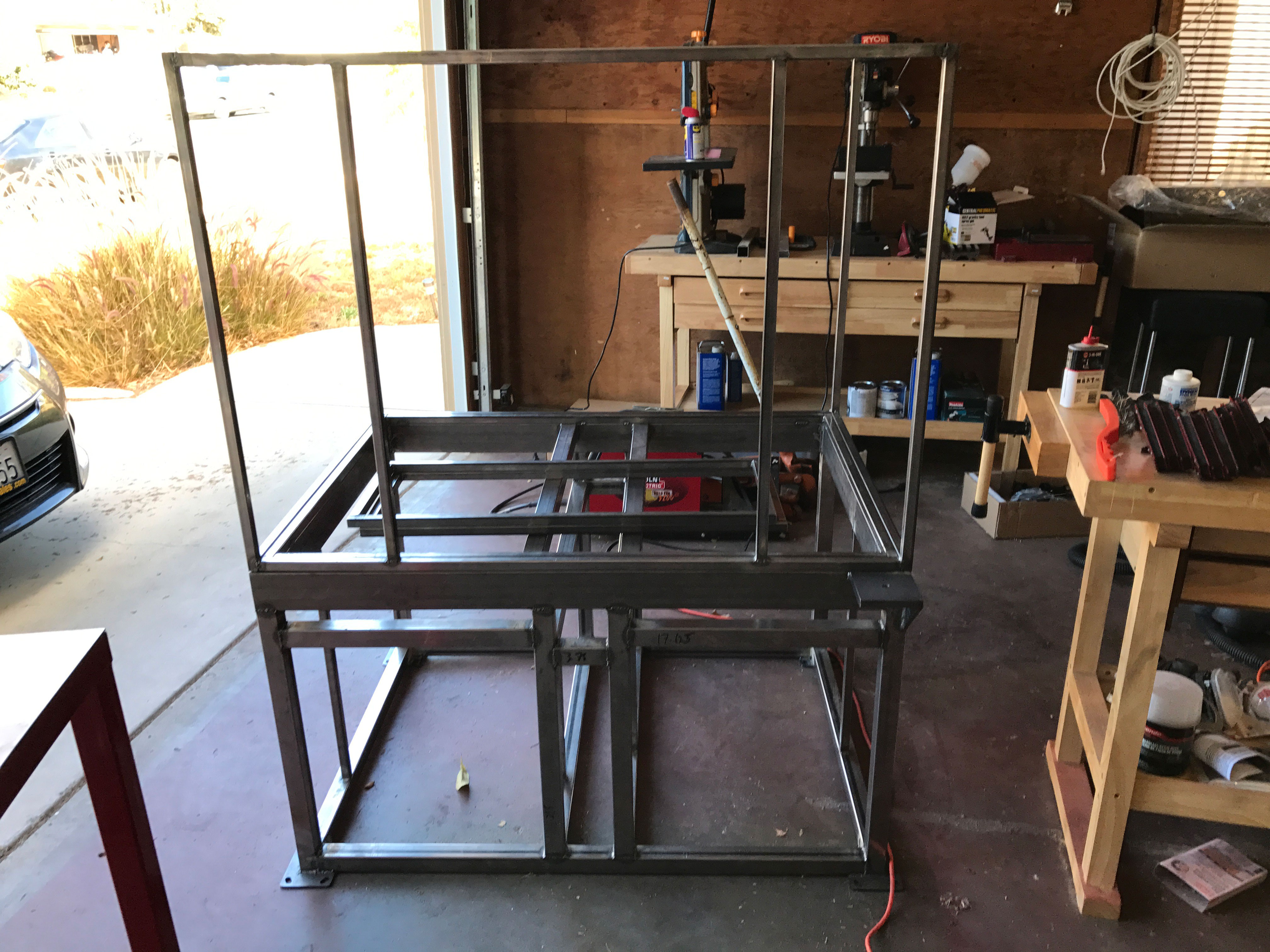
    0.75" square tubing was used to build the enclosure section.

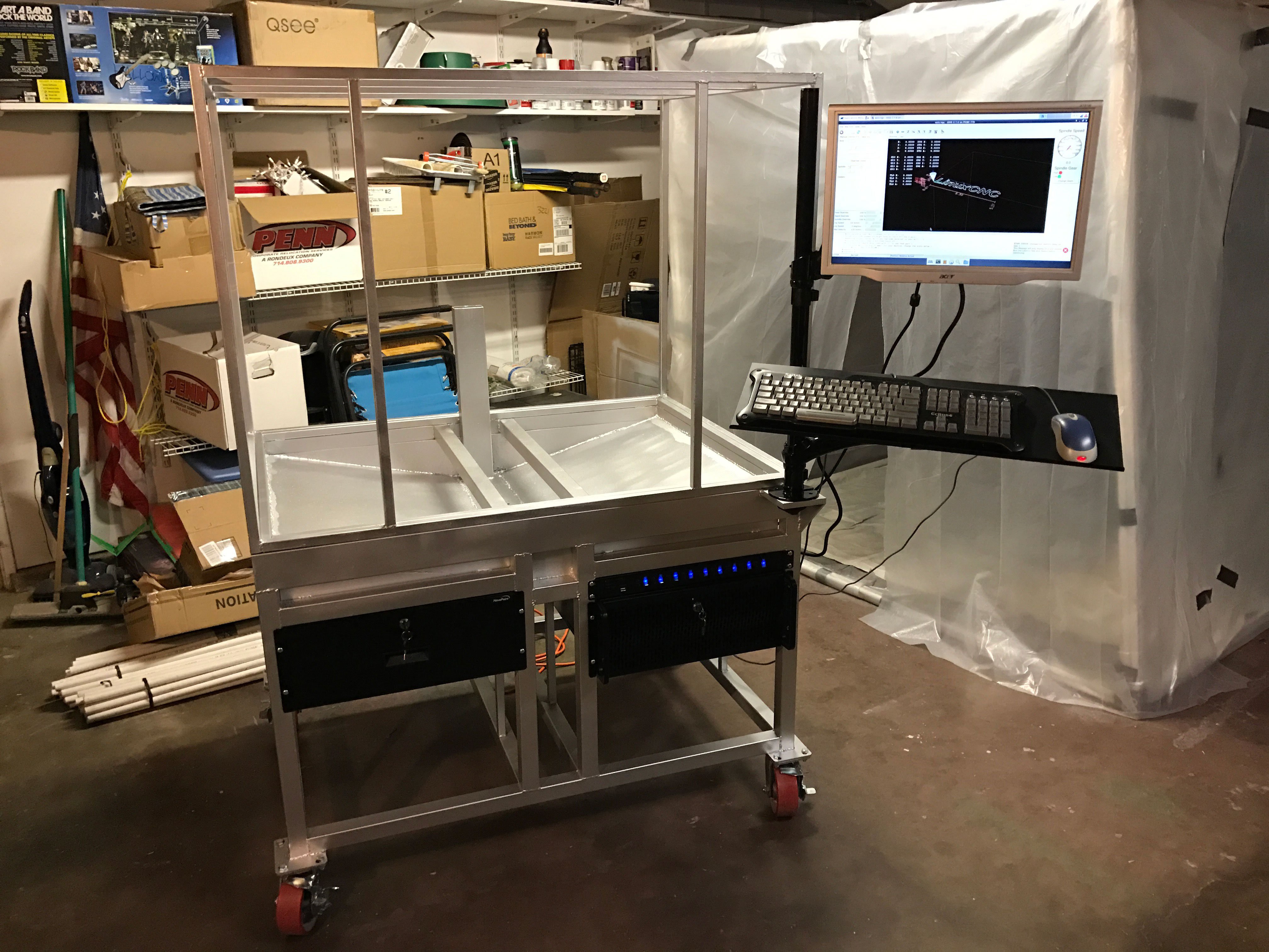
    Completed enclosure.

    Welding in the coolant tray.

    Coolant drain holes.

    Attaching the heavy duty casters after being painted.

    Mounted a 4U drawer on the left and a 9 channel power strip and a 4U server on the right.

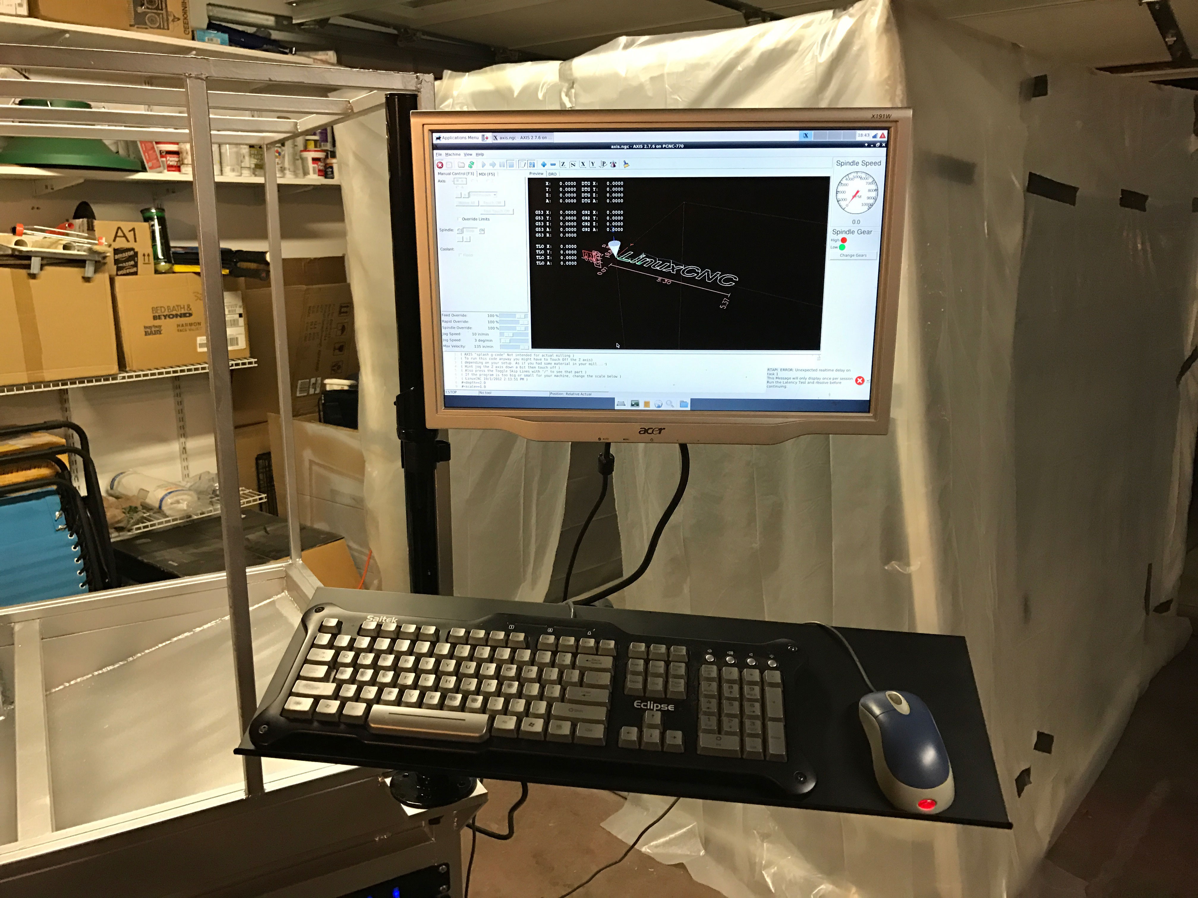
    LinuxCNC running on the server, with the display and keyboard mounted.

    The arms can swing and be adjusted vertically.

    The enclosure is still missing the acrylic sheets and the coolant system has yet to be installed. The mill was disassembled completely and cleaned. It will be reassembled directly on the new stand pretty soon.

  • Quick mill update

    james.moran06/28/2015 at 00:31 0 comments

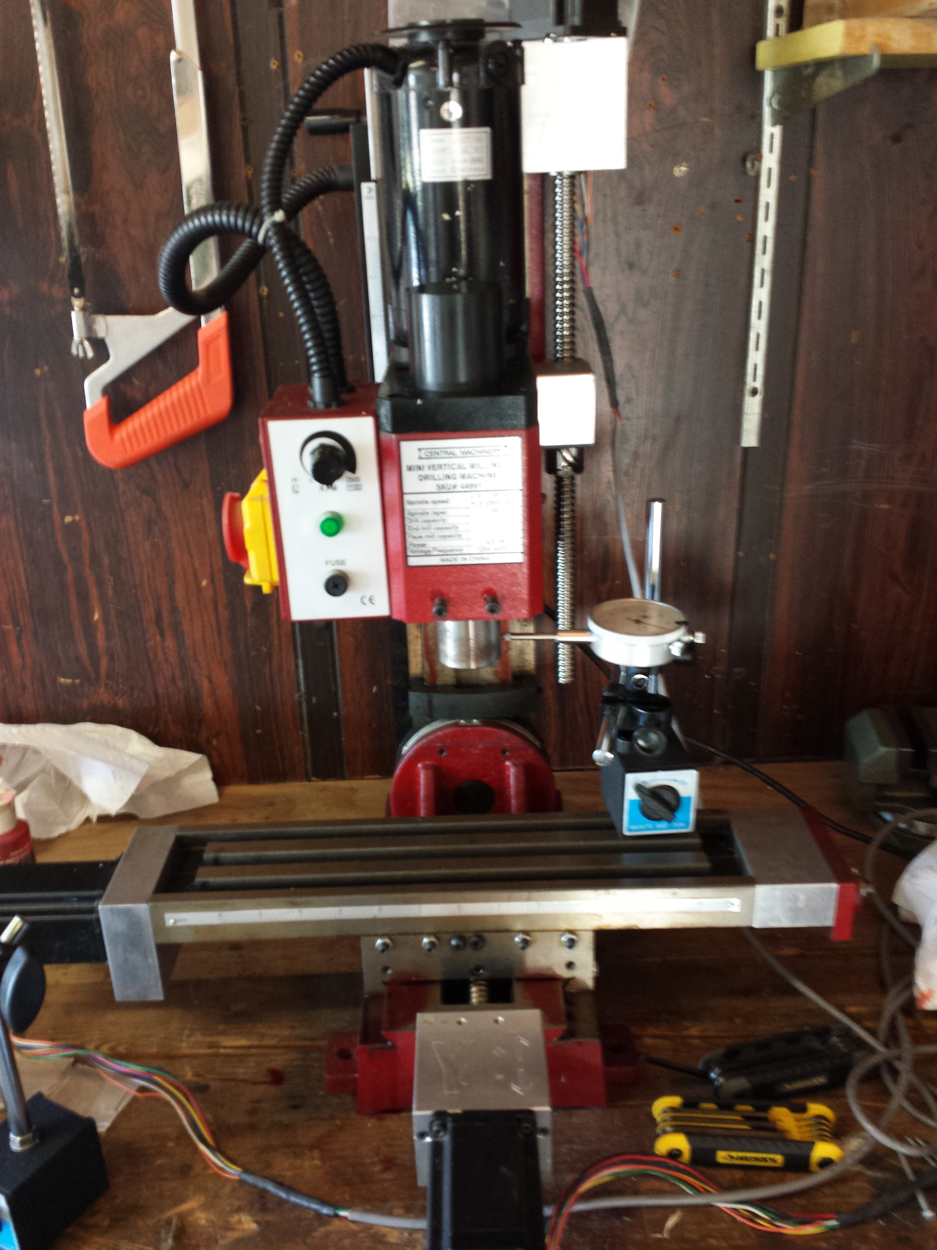
    We did a bit of work last weekend, primarily on getting the mill itself ready. Here it is cleaned off and setup in it's new home:

    Once everything was connected (mill, CNC1000, GRBLWeb laptop, etc) we had to calibrate it. GRBL has a bunch of settings used to determine things like how many steps of a motor equal 1 mm of travel or limits on movement rate. The main ones we had to worry about where $100, $101, and $102 - the steps per mm in X, Y, and Z respectively. There's a formula given on that GRBL page for working it out based on the motor and controller being used. With that done, we used a set of magnetic dial indicators (specifically this set) to test both the accuracy and repeatability of commands. Below we see the indicator set to measure X-axis movement:

    With this in place we sent a series small commands (like "move 2 mm in +X" five times, then "move 2 mm in -X" five times) to check our setup. We had good and bad results here: good being the repeatability (each individual command moved the same amount and we could always reliably return to 0) and bad being the accuracy (a 2mm command resulted in ~1.7mm of travel). Our results were consistent across all 3 axes, with the Z being slightly more troublesome than the others (expected since it has to deal with gravity).

    We didn't finish the setup and calibration - after a couple of hours we hadn't made any progress and decided to cut our losses for the day. We did find an error in the step/mm calculations, so next time we get a chance to work on this we'll put in the new value and see if that fixes it.


  • Making An Enclosure

    Evan Li06/26/2015 at 22:30 0 comments

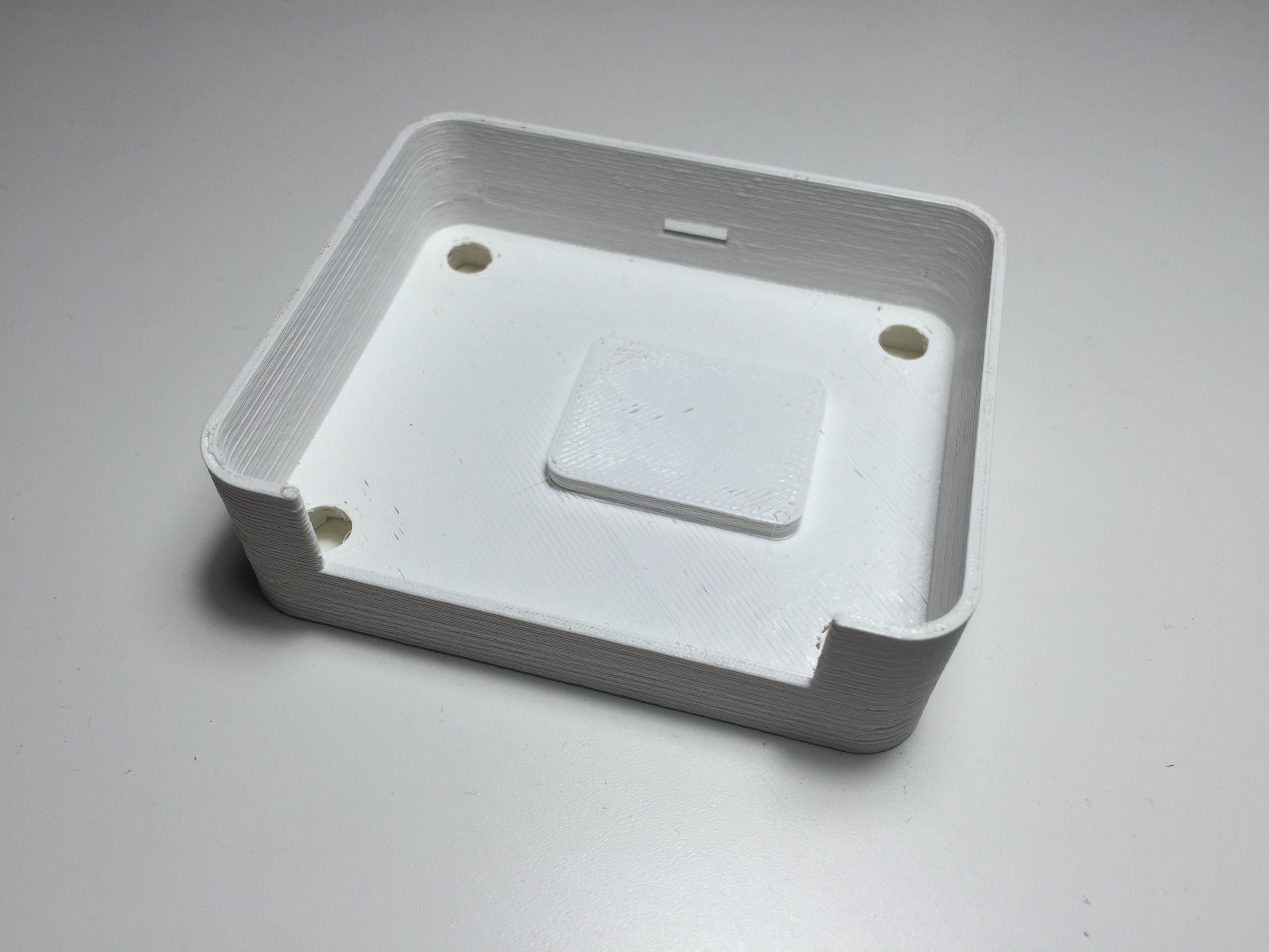
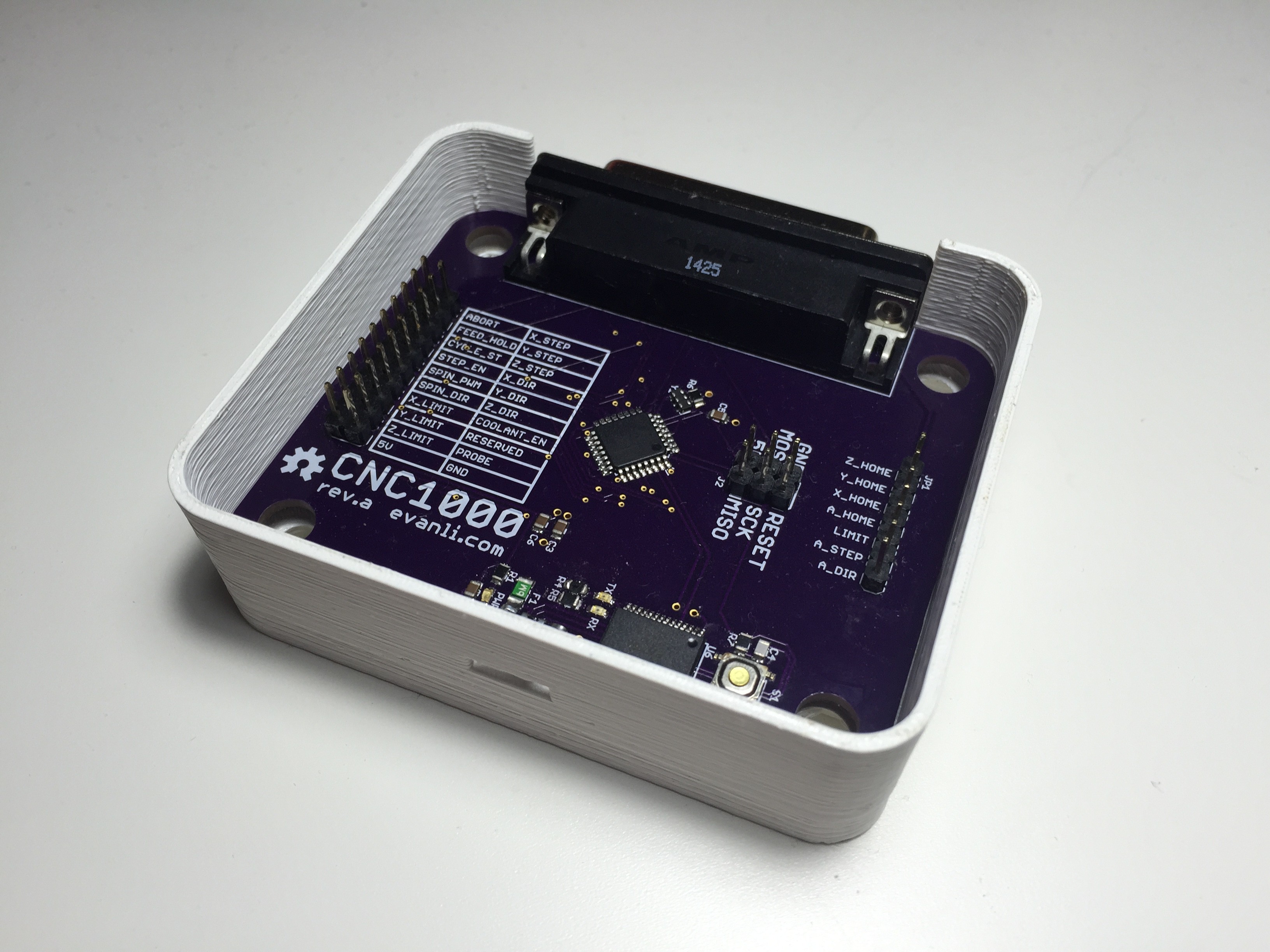
    Since this new board is going to be controlling a machine spitting out shards of metal, it seems prudent to provide an enclosure for it. Modeled up an enclosure in solidworks and after a few hours on the ol' 3D printer, it was done.

    Since the board has through-hole components, I added a small pad for the PCB to rest on. There is a cutout for the the parallel port and the USB port.

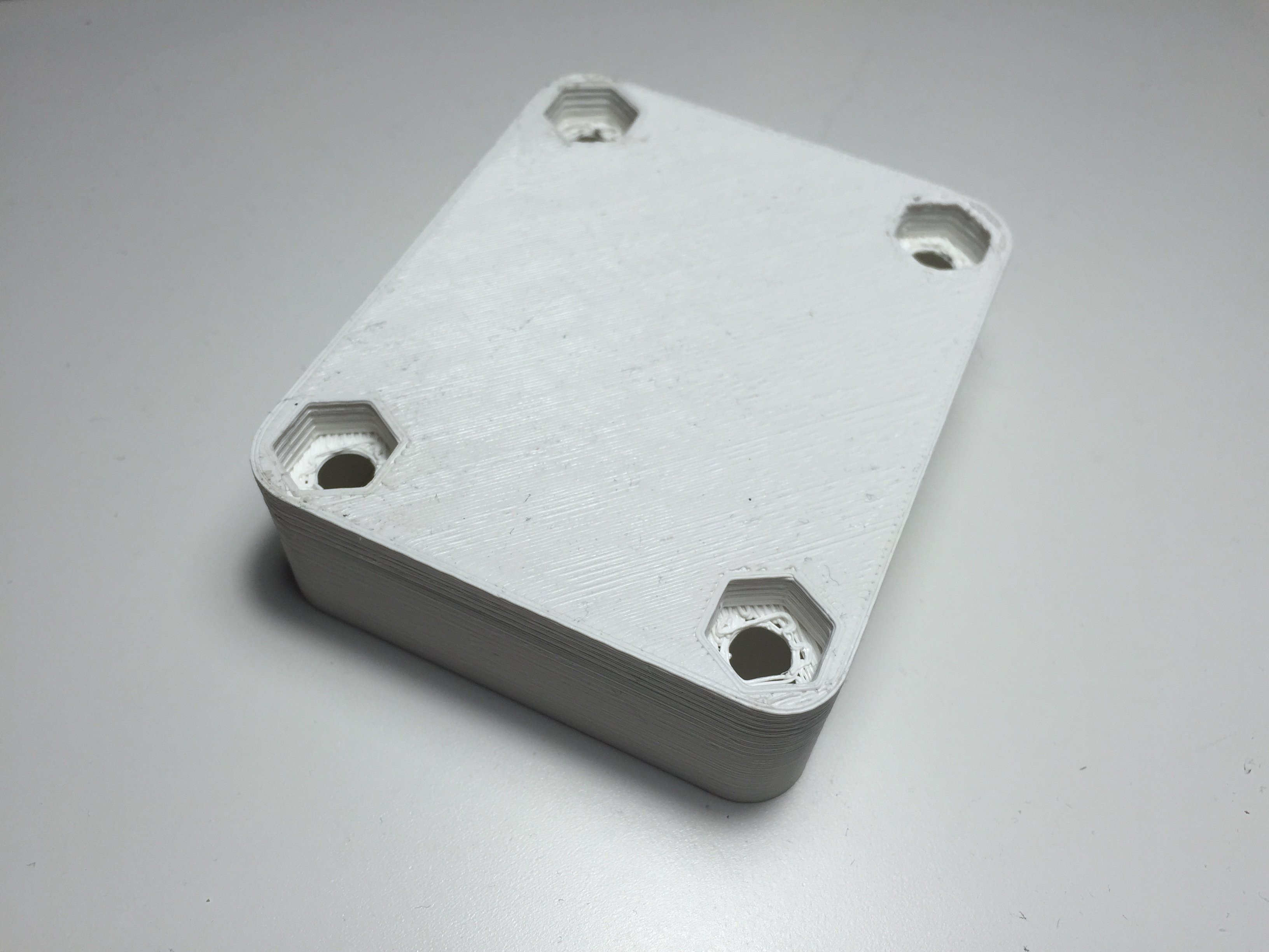
    On the bottom of the enclosure, there are recesses that fit and capture 1/4-20 nuts.

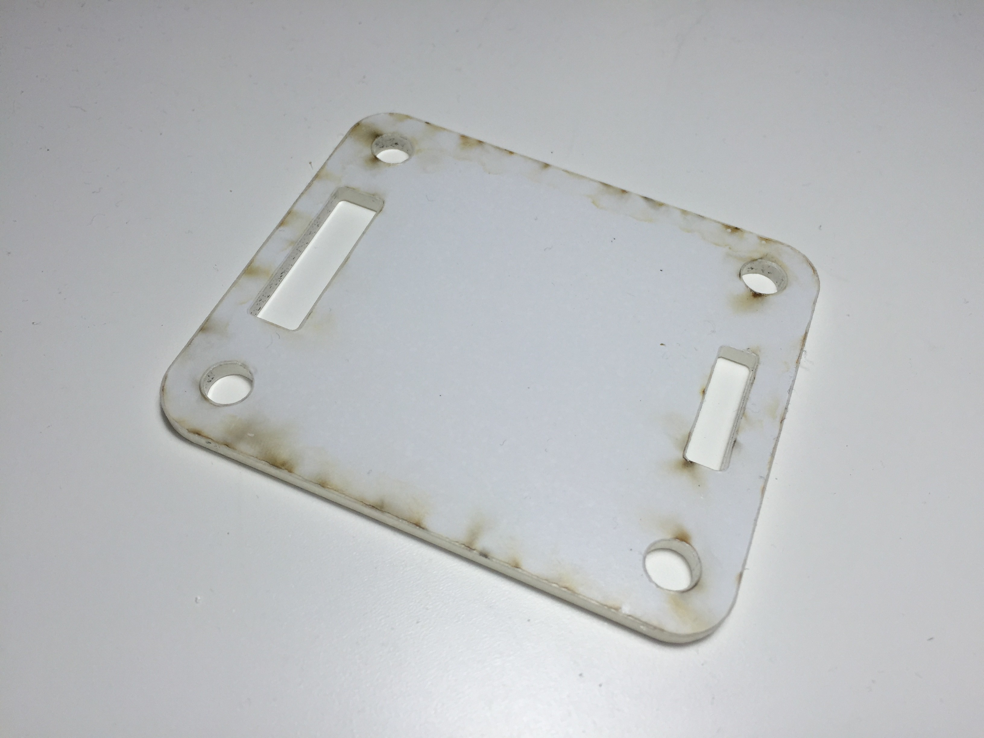
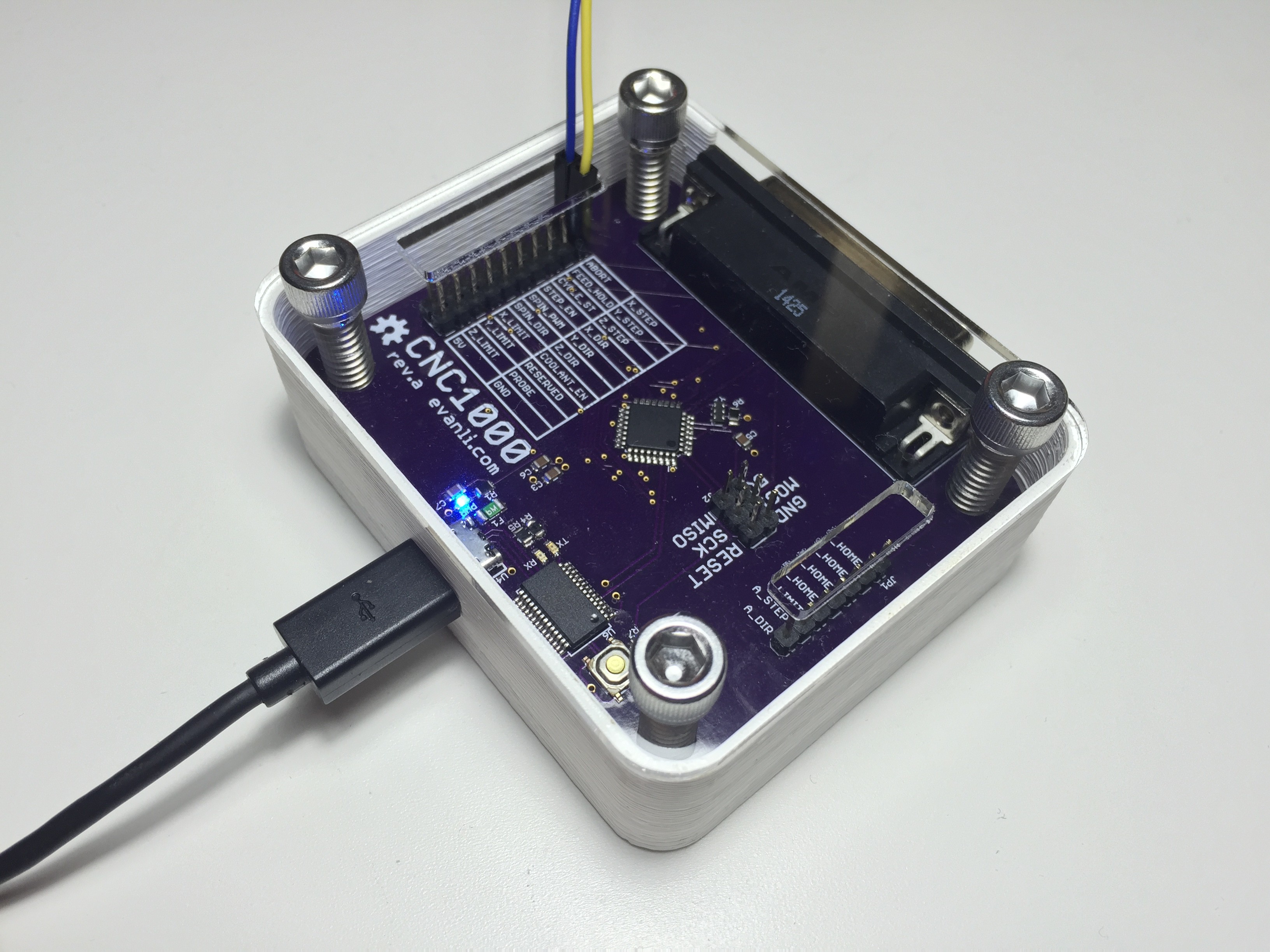
    The top of the enclosure is a laser cut piece of acrylic with cutouts for the bolts and some openings to access the headers.

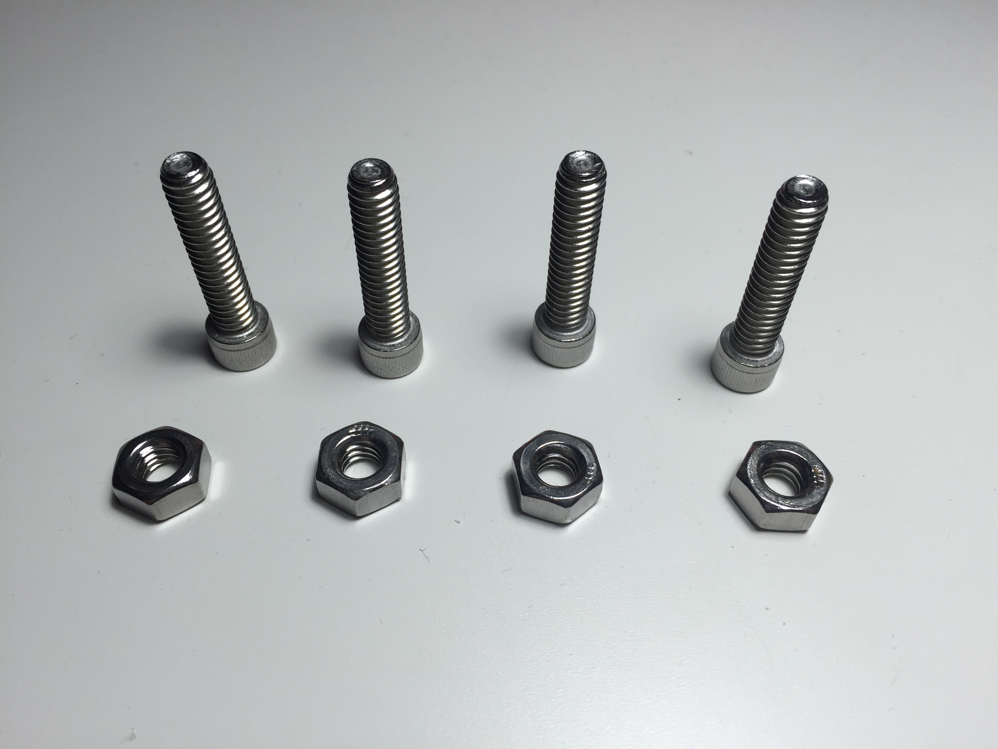
    These are four 18-8 stainless 1/4-20 bolts that defined the final height of the enclosure.

    The model has tolerances for my 3D printer incorporated into it, so it fits like a glove.
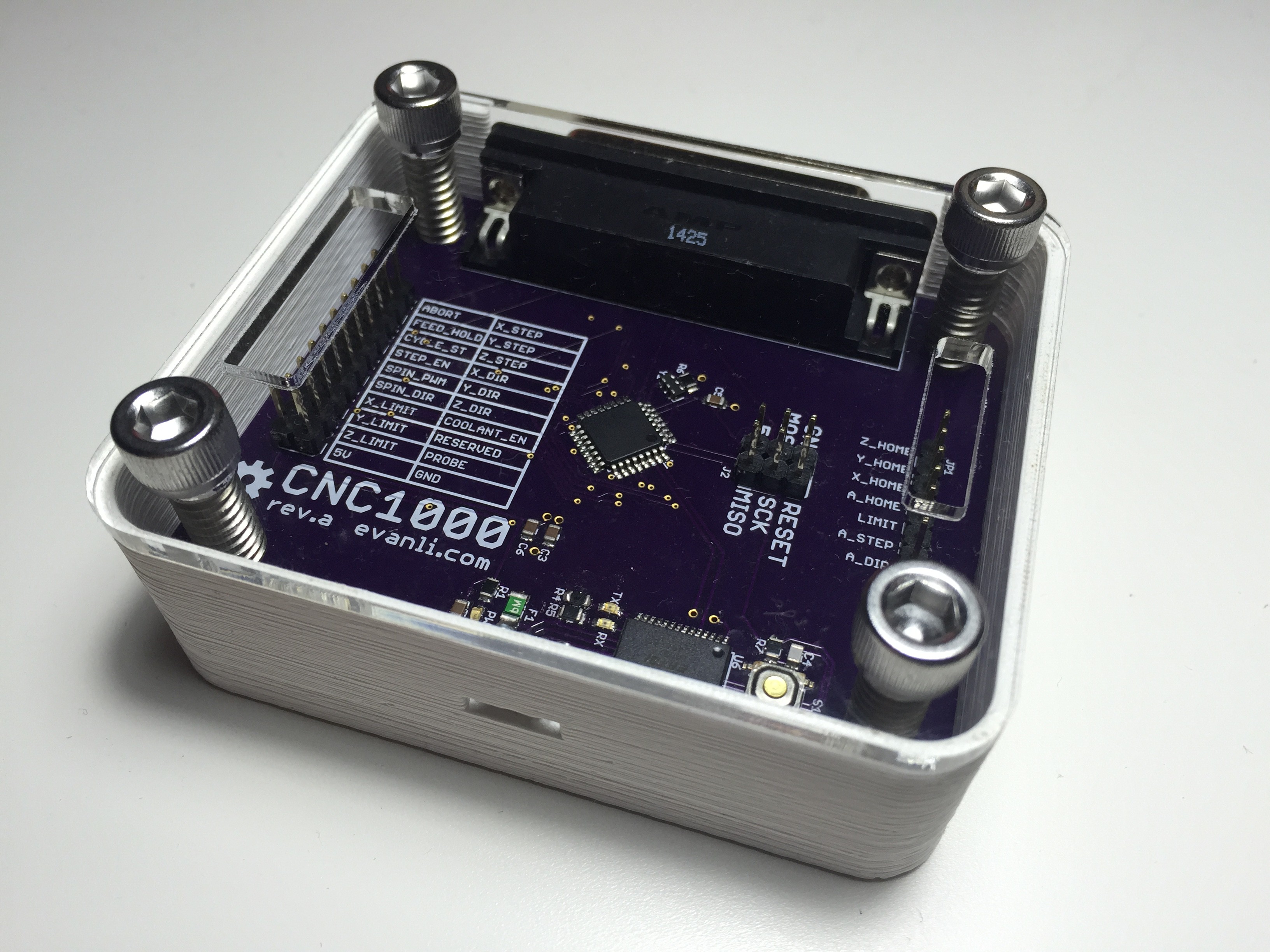
    With solid planning and good CAD work, things can fit together perfectly the first time.

    Fully assembled and ready for final testing. I noticed a minor oversight during testing. The reset button isn't easy to get to.

  • Progamming the CNC1000

    Evan Li02/24/2015 at 07:07 0 comments

    With the board complete, we now move on to testing and programming. Couple things to check with an multimeter before applying any power. Check that there's no short between the supply voltage and ground. Then I check that there is continuity between my header pins and pins on the MCU. This is good for checking if there are any shorts caused by solder bridges.

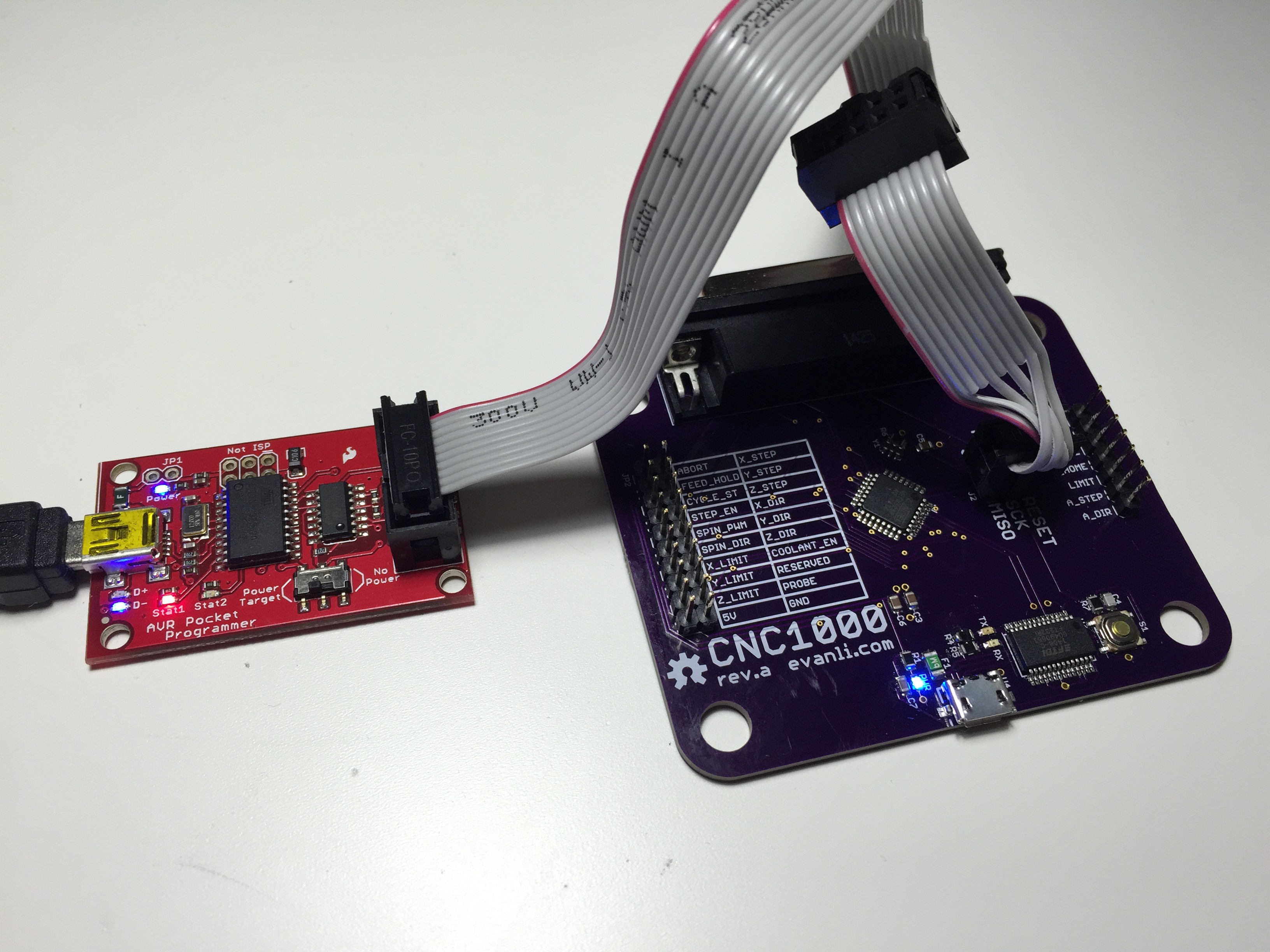
    To program the ATMega328P I use a handy AVR Pocket Programmer from Sparkfun. Since it's based on a USBTiny programmer, the Arduino IDE can burn the bootloader onto the chip.

    The LED lights up, which is a good sign. Once the bootloader has been burned on by the Arduino IDE, we can use USB via the FTDI chip.

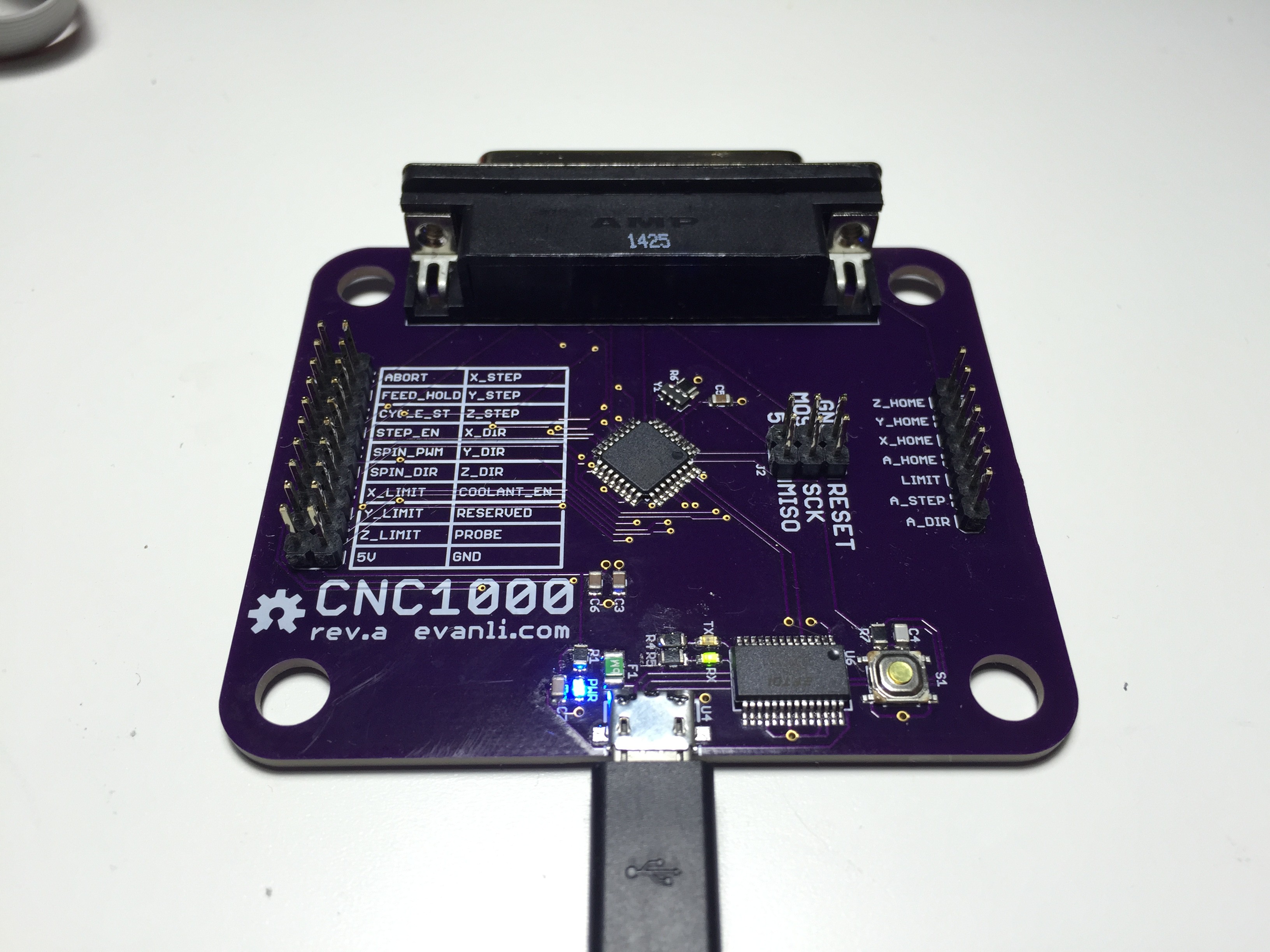
    Power LED, RX and TX LED are all working. My computer picked it up as COM16.

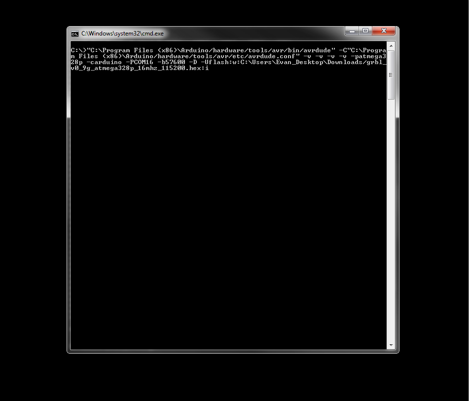
    You can grab the latest compiled hex file for GRBL from GRBL on Github. Once you have that, you can load the hex wit AVRDude, which is included with the Arduino IDE.

    Pretty long command to get it going. It sets the chip, platform, com port, and BAUD rate, as well as the hex to be loaded. Check AVRDude for more info on that.

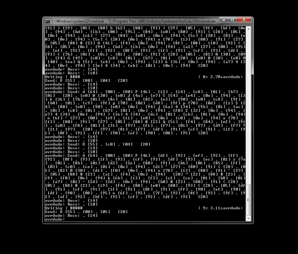
    It takes a few minutes to load GRBL via AVRDude.

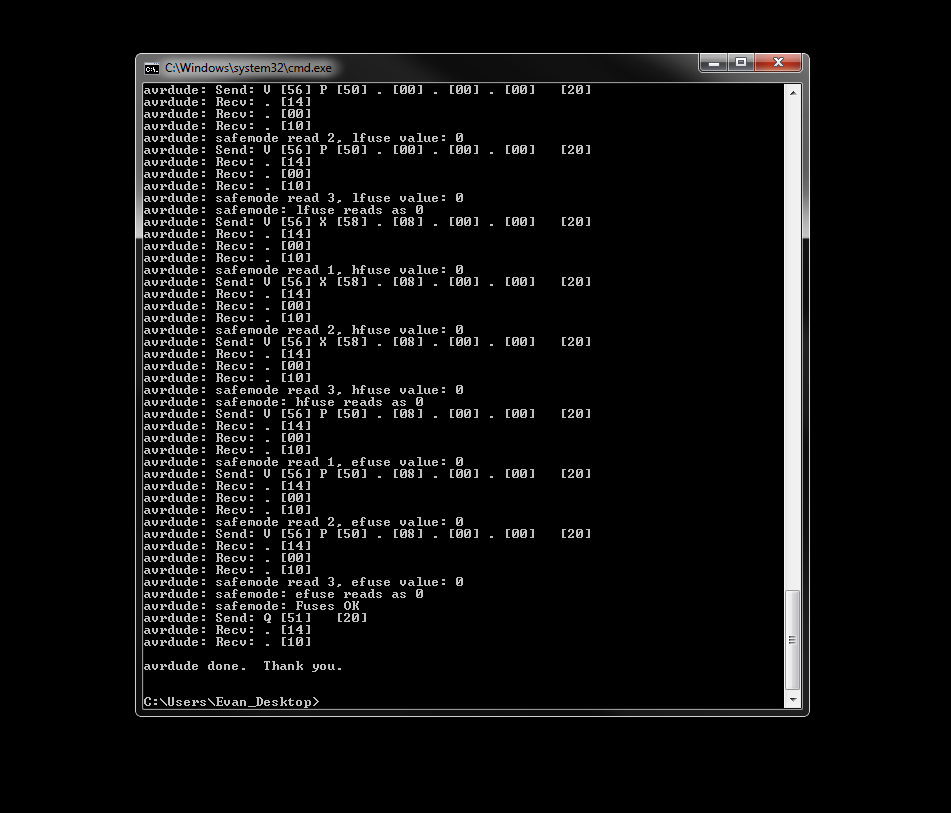
    When it's done, the CNC1000 should be ready to go.

  • Getting GRBLWeb up and running on an x86 laptop

    james.moran02/24/2015 at 06:07 0 comments

    *NOTE* All of this was done several weeks ago, so I'm going to update this post piecemeal as I go through my notes and logs to re-create exactly what I had to do.

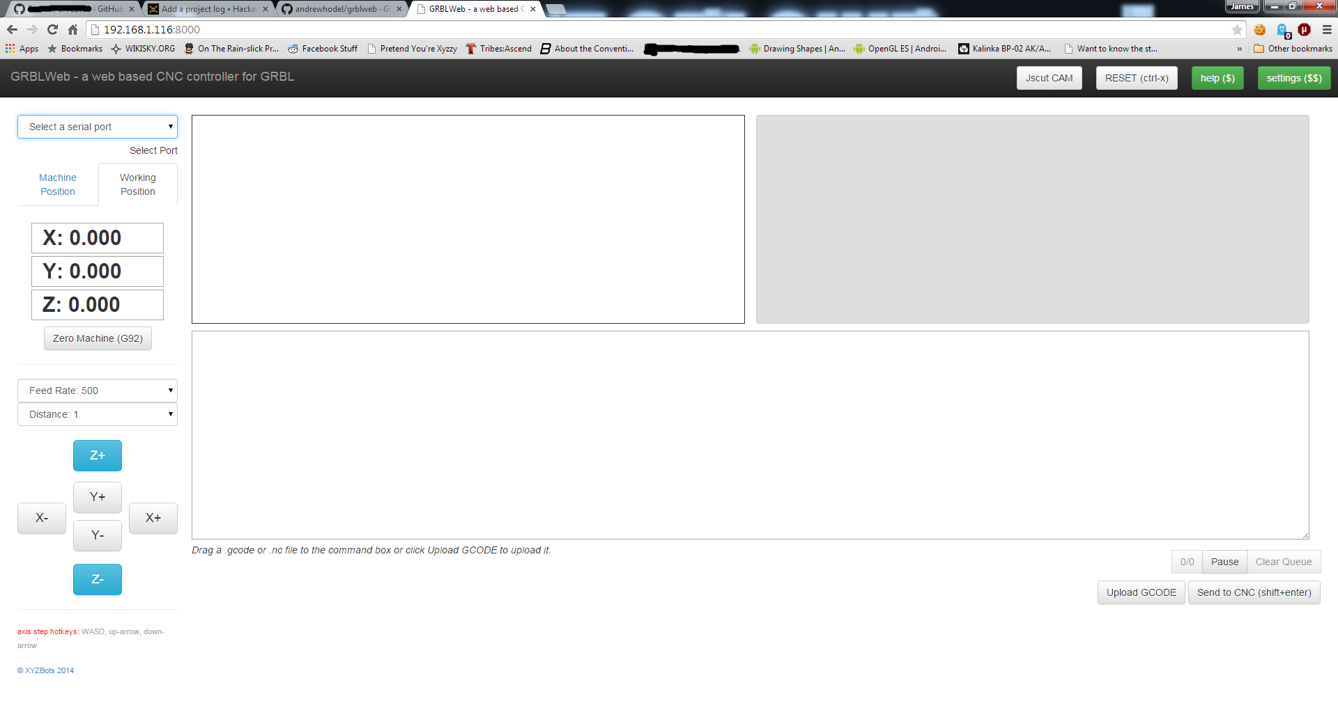
    GRBLWeb is a web-based CNC controller designed for use on Raspberry Pi systems.The idea behind it is that you install this on your RPi and connect a GRBL device (an Arduino of some flavor) through USB to create a CNC control machine accessible from anywhere on your local network. I don't have a Rapberry Pi but I do have an old Acer laptop running Fedora Linux so I figured I'd use that instead.

    There's nothing special about the laptop - it's a 32-bit Celeron M processor running Fedora 20 with kernel 3.17. Stock install, nothing unusual to start with.

    Since I can't use the pre-built RPi image I'll have to install from source. GRBLWeb provides instructions right on their site:

    git clone https://github.com/andrewhodel/grblweb.git
    cd grblweb
    npm install
    Simple enough, right? Well, it failed during the install because you need node.js. If you've already got that installed, cool! You're ahead of where I was. This wound up being the only part that caused me any difficulty - getting the right node.js packages installed was oddly complicated, although I suspect that someone who actually uses it on a more regular basis would get it immediately.***TBD: Actual instructions for node.js installation ***

    Once node.js is set up the GRBLweb install should succeed with no other issues. I don't want to have this running constantly on my laptop so I just use the standalone start up when I need to use GRBLWeb:

    node server.js
    At this point by opening a web browser on my laptop and going to 127.0.0.1:8000 I can see the GRBLWeb control page. Huzzah! Now let's try it on another PC on my network by going to $laptop_ip:8000....

    404!?!

    Ah, right - firewall's probably blocking it. Opening up port 8000 (protocol: TCP) in my firewall config did the trick (the port can be changed in the config.js file located in the grblweb install directory). Now I can get to it from any machine on my network.

    At this point all I've verified is that GRBLWeb is installed and accessible. I haven't set up GRBL itself on my Arduino yet to check that communication - that'll come soon.

  • Assembling the CNC1000

    Evan Li02/21/2015 at 21:58 0 comments

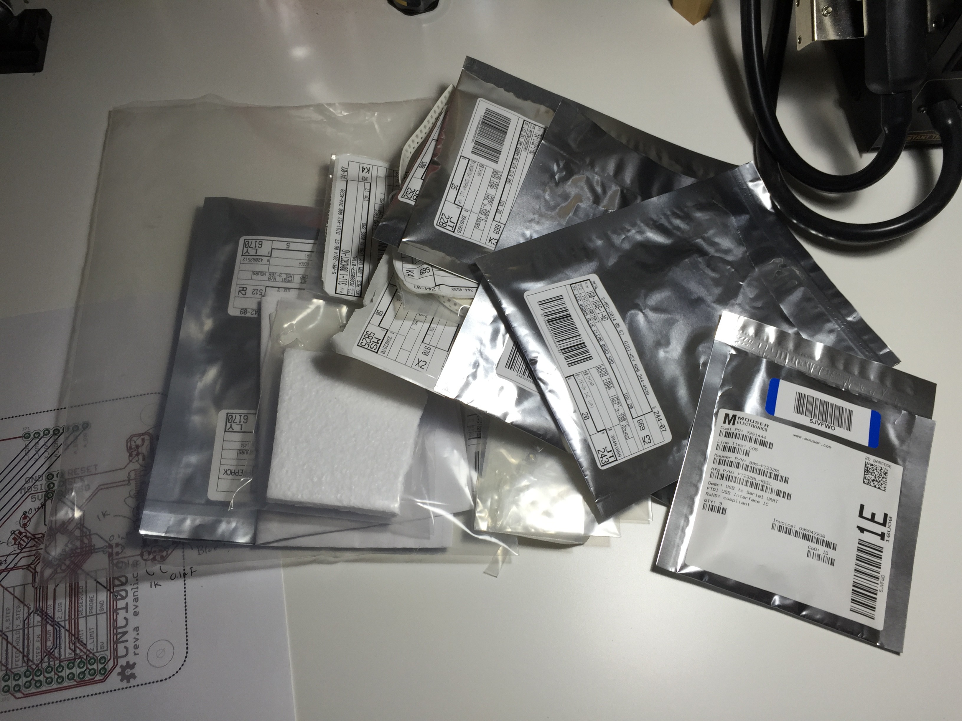
    Pulled all the needed component out of my existing inventory. It's nice when you have accumulated lots of basic parts like capacitors and resistor, save a lot of time having to reorder them. I also like to use an annotated printout of the PCB so I know where everything goes.

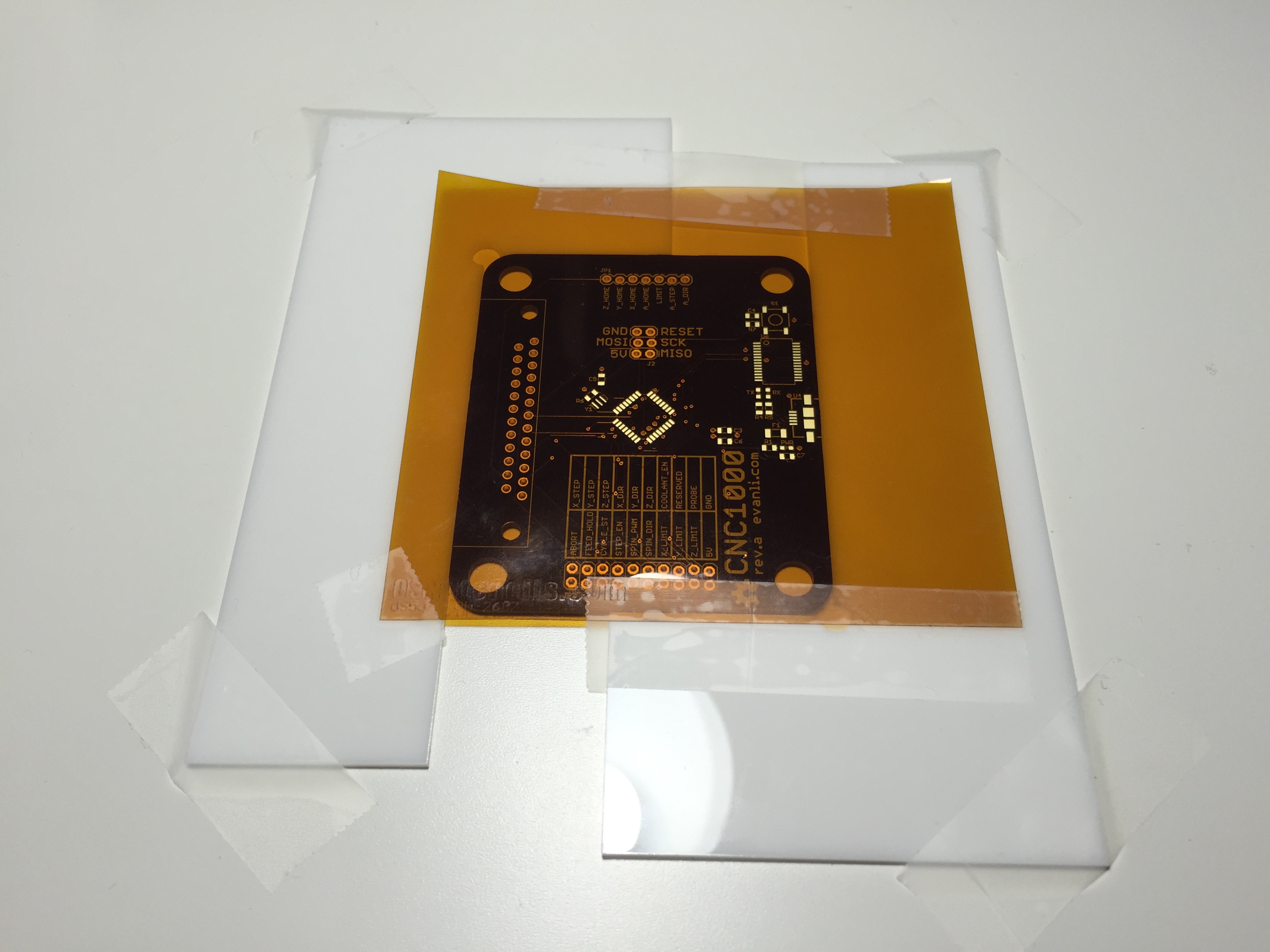
    Putting on solder paste is always a delicate task. Basically I just taped the PCB in place with some acrylic L shapes. The stencil is aligned and secured in place with more tape.
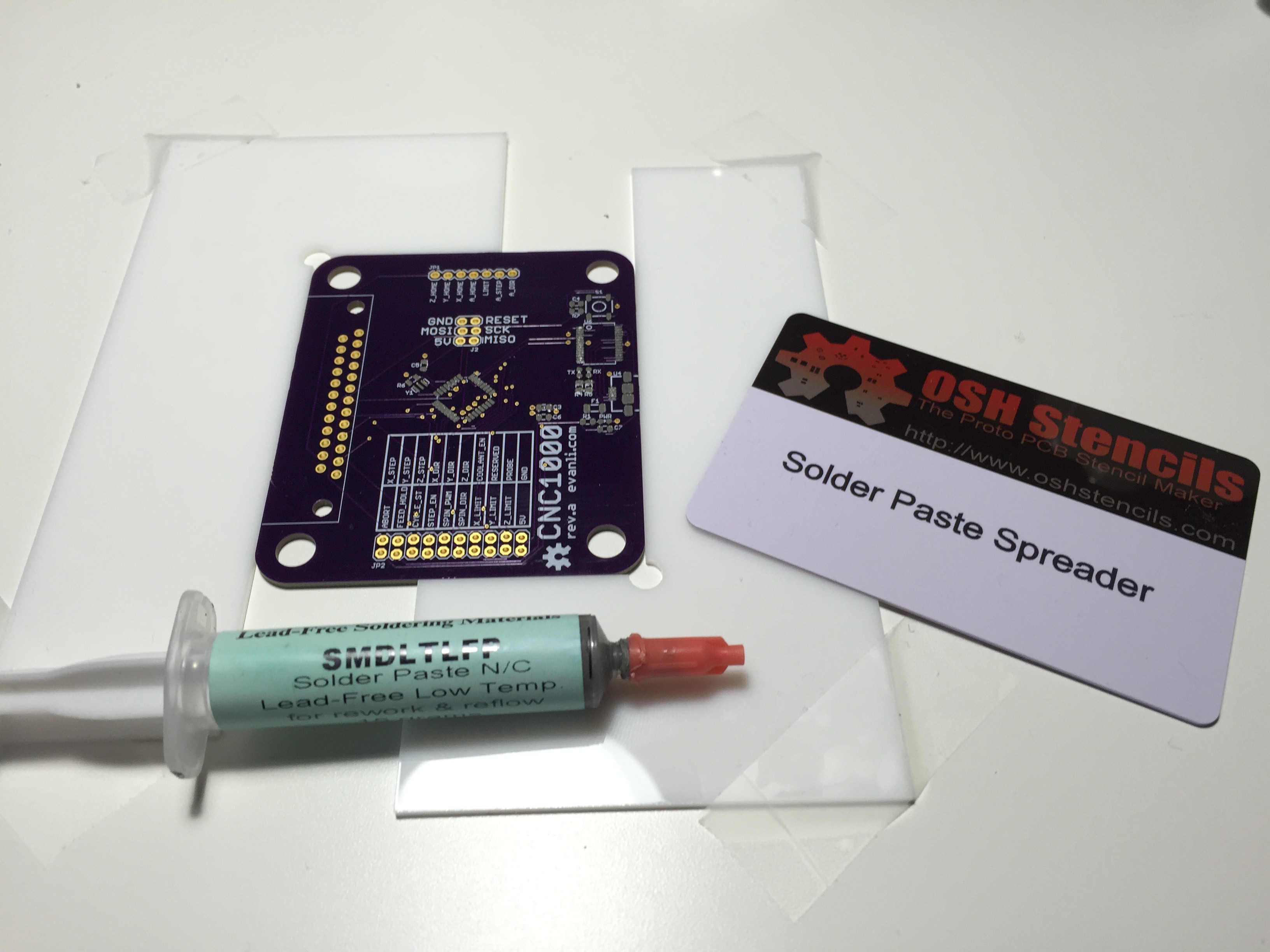
    Dump some solder paste on and spread it with a convenient card from OSH Stencil.
    Solder paste applied on all the pads.

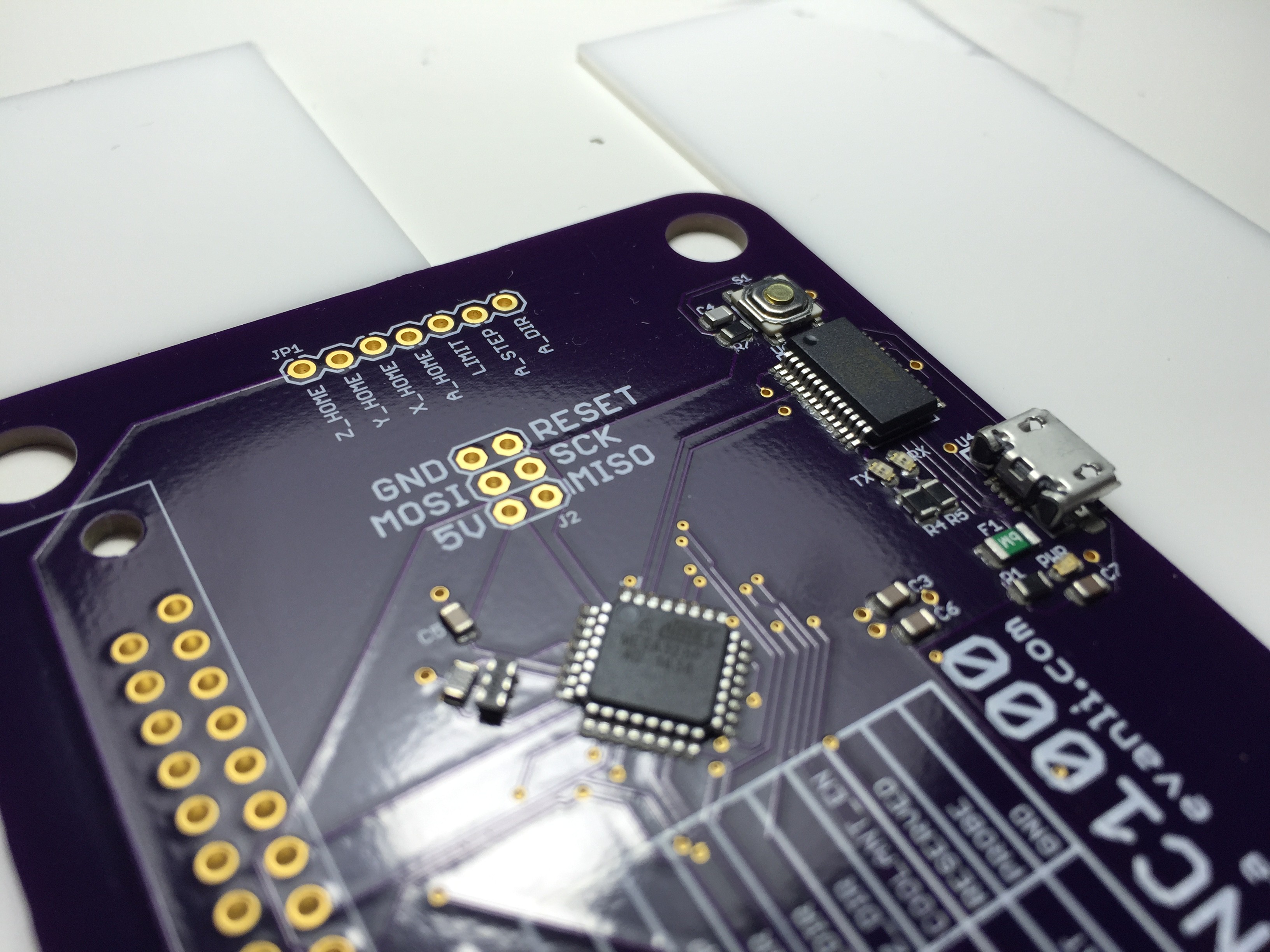
    Populating the board is also a delicate process. Pull the component out and carefully plop them down on the correct pads.

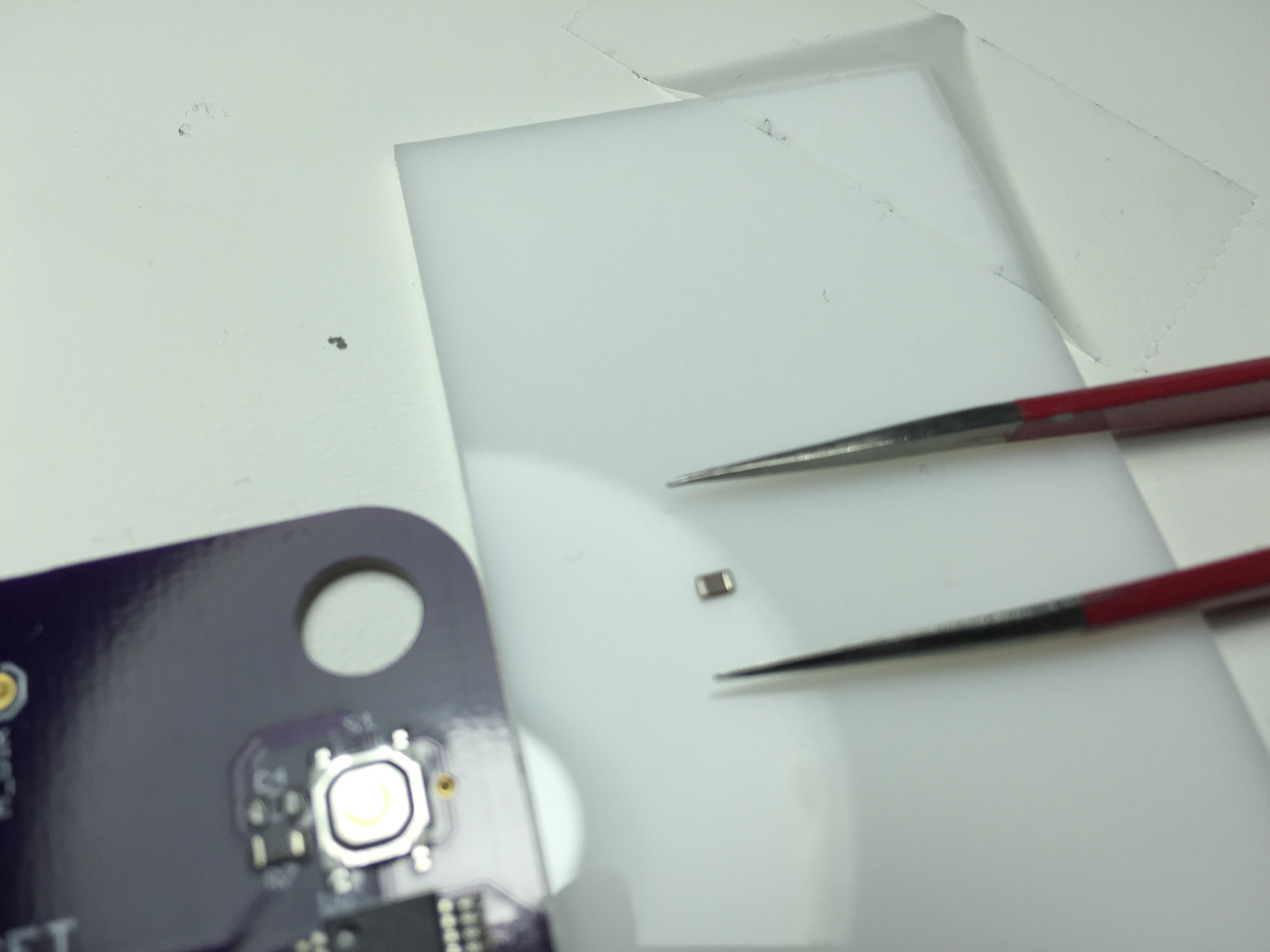
    Switching tweezer types for the tiny passive parts.

    All the parts are populated. The parts can be a little misaligned as surface tension of the solder will pull the parts into place.

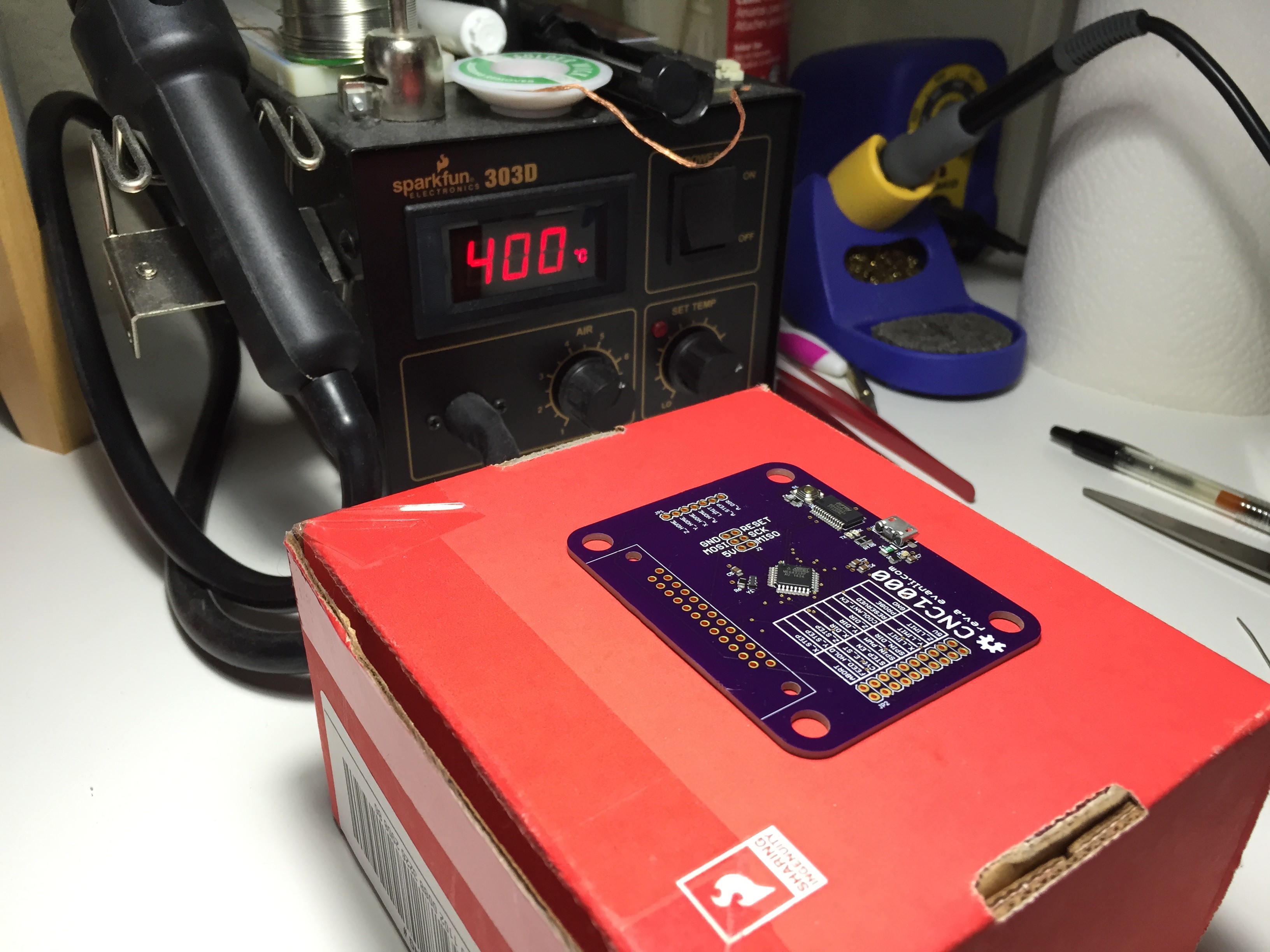
    For boards of this size and component count, I use a hot air rework tool to reflow the solder. For larger boards with more parts, the skillet or toaster oven route is more time effective.

    All the SMD parts are reflowed. Any bridged connections I fix with a fine tipped soldering iron.

    Populated the through hole parts and solder them with lead free solder by hand.

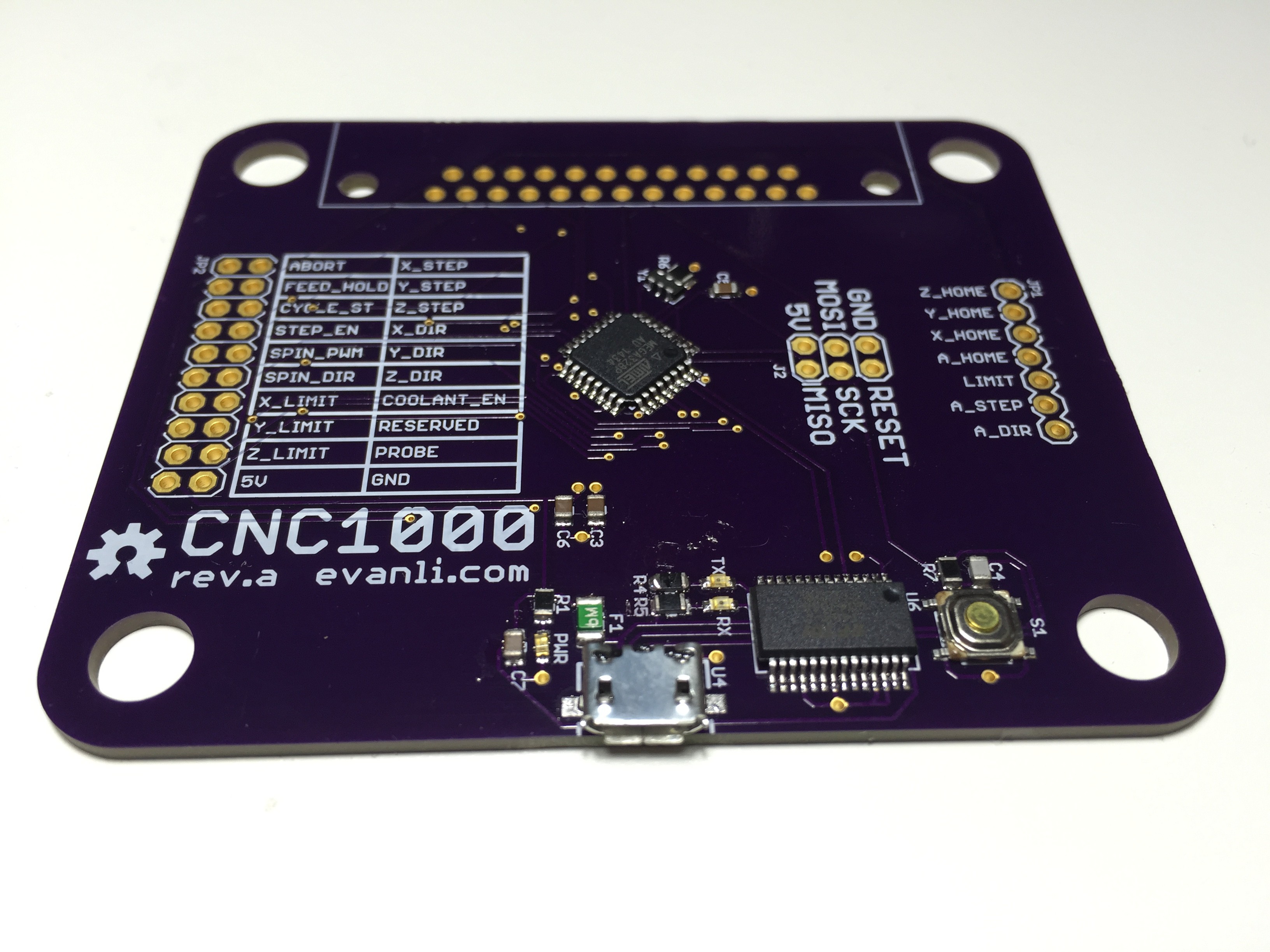
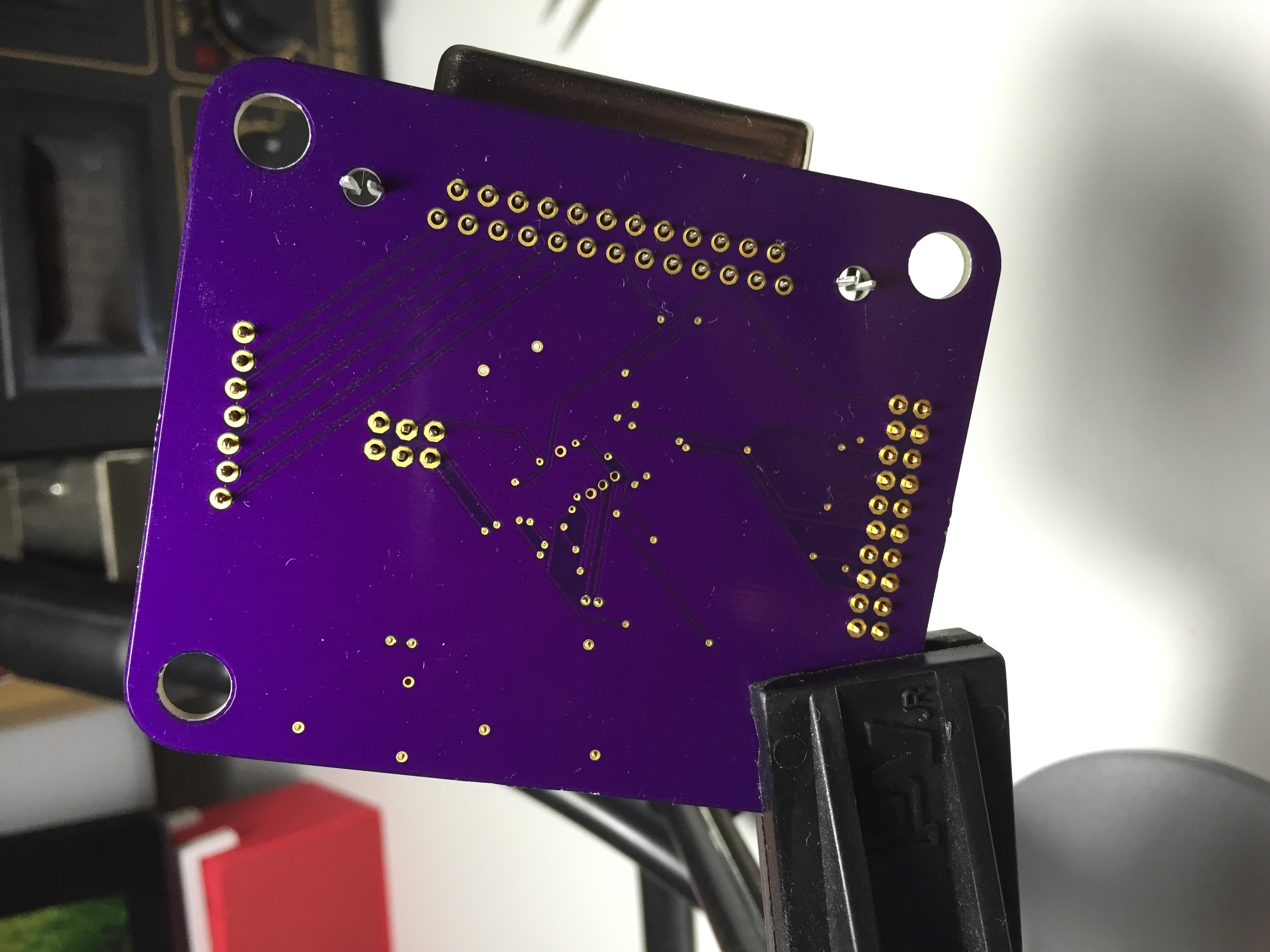
    Completed board, ready for testing and flashing on the firmware.

  • Checking the PCB and Stencil

    Evan Li02/21/2015 at 20:17 0 comments

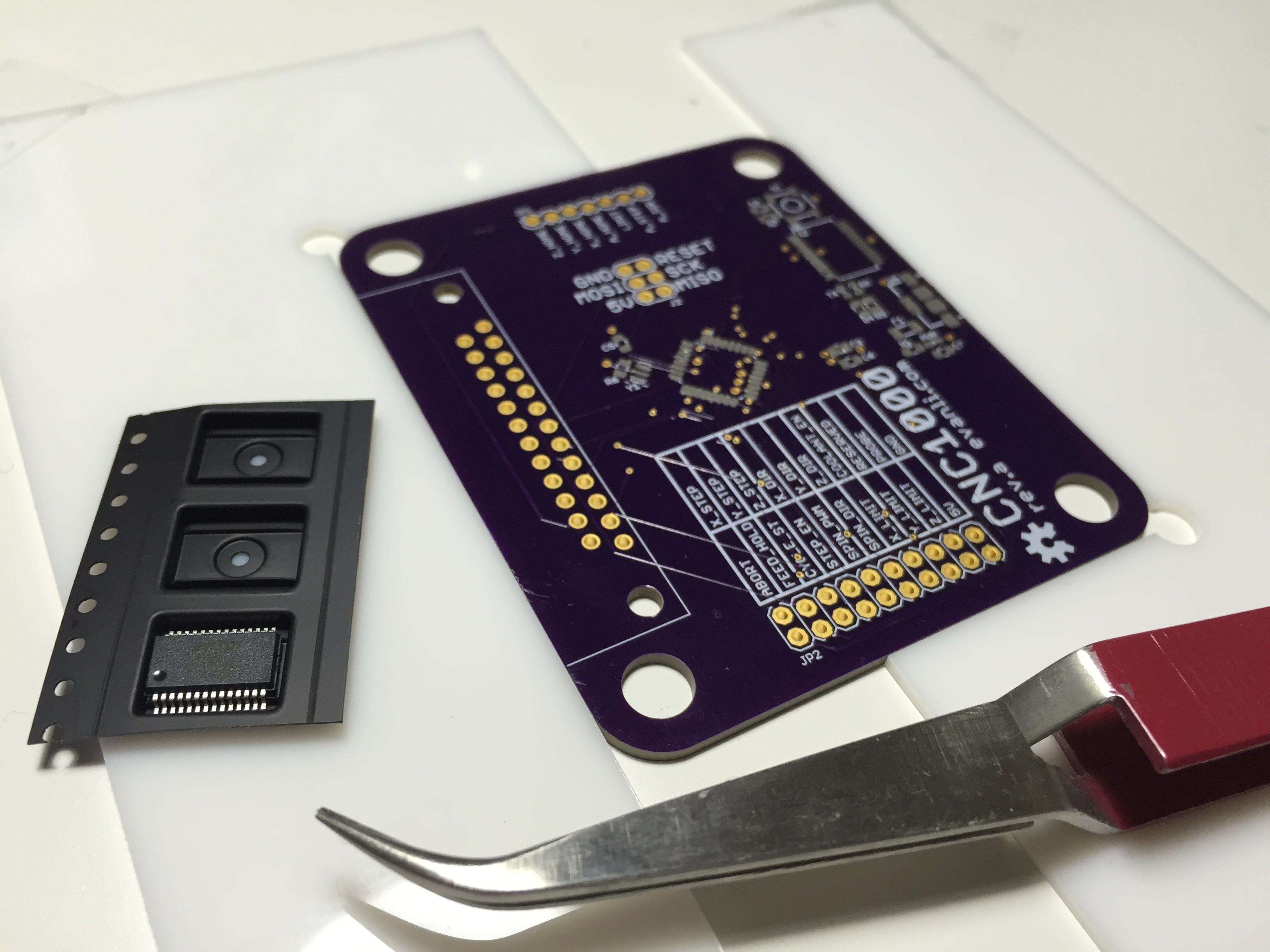
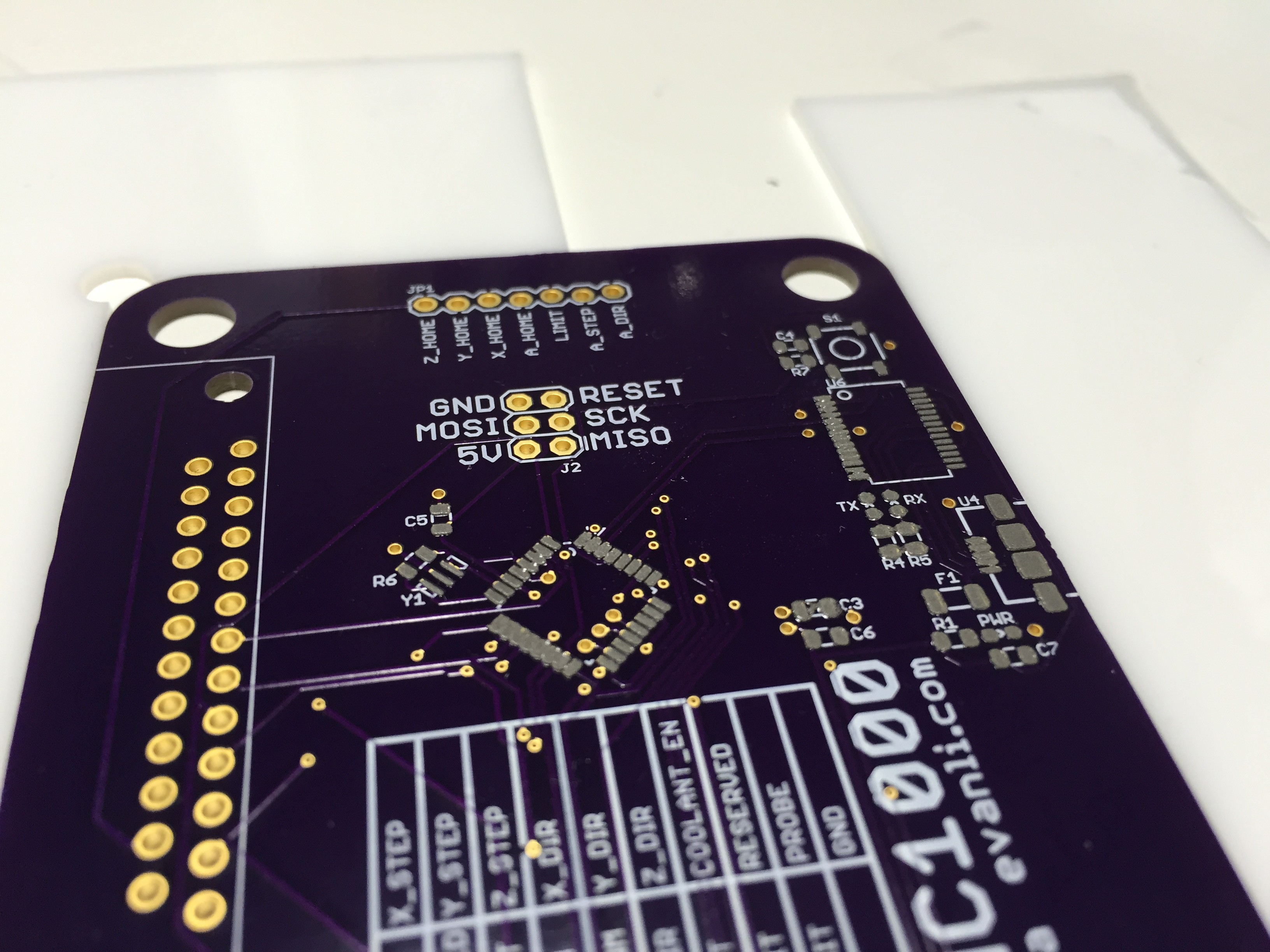
    As always, OSH Park produces some great PCBs for a very reasonable cost with pretty quick turn-around time. This was the first time I had used OSH Stencil, but they were quick and the stencil looks great.

  • Components

    Evan Li02/21/2015 at 20:13 2 comments

    All the various components for the new USB based controller have arrived. PCB's from OSH Park, stencil from OSH Stencil, and parts from Digikey. I still have quite an inventory of components so the Digikey order was just for parts specific to this project.

View all 8 project logs

Enjoy this project?

Share

Discussions

Similar Projects

Does this project spark your interest?

Become a member to follow this project and never miss any updates