The Big One
-
Voltage Output Mode
02/05/2015 at 04:35 • 0 commentsI was working on my power supply design today, and found myself in need of a variable voltage supply (to simulate the output of a DAC driven by a microcontroller, which will eventually allow for variable voltage and maximum current setpoints). Well, wait a second here... I already have a DAC!
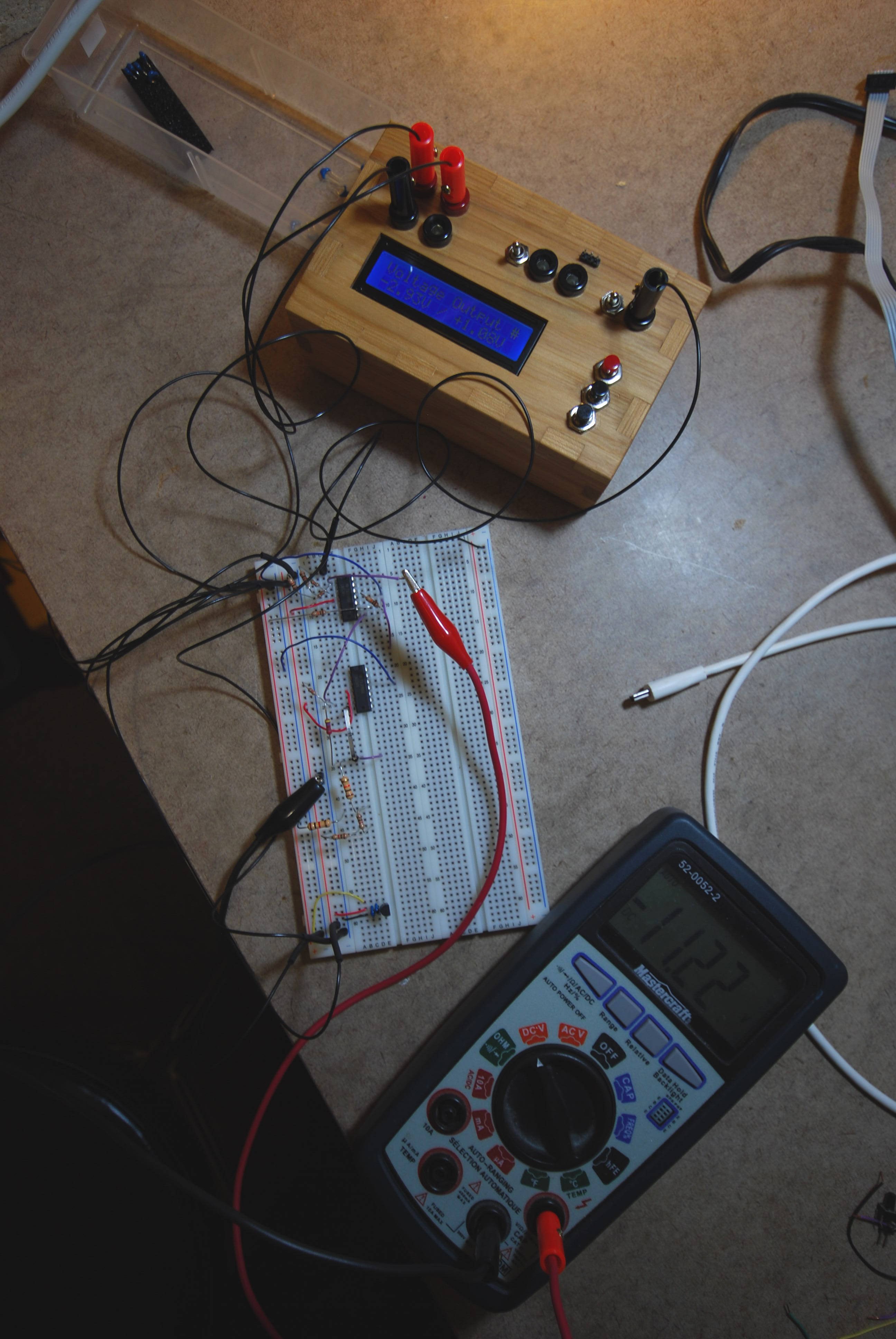
The new mode (creatively called "Voltage Output"), simply writes an 8 bit value to the DAC, and lets it output a voltage. Since the analog channel can have a range of -5 to 5V or 0 to 5V, I show both values (i.e. "-2.93V / +1.08V). Depending on the position of the range switch, the output will be one or the other of these two values.
![]()
(In this picture the multimeter is measuring the post-op amp voltage, not the input voltage, which is why it shows -11.22 instead of +1.08)
I have calibrated it in the source code with actual values found in my system. The min / max values are therefore dead on; in between things are not perfect to two decimal places, but it is generally accurate to one decimal place. (I assume that it is due to non linearities in the DAC and op amp that cause the differences; regardless, it is perfectly fine for what I need, and best of all it cost nothing more than an hour of programming time).
Cheers
-
User Interface
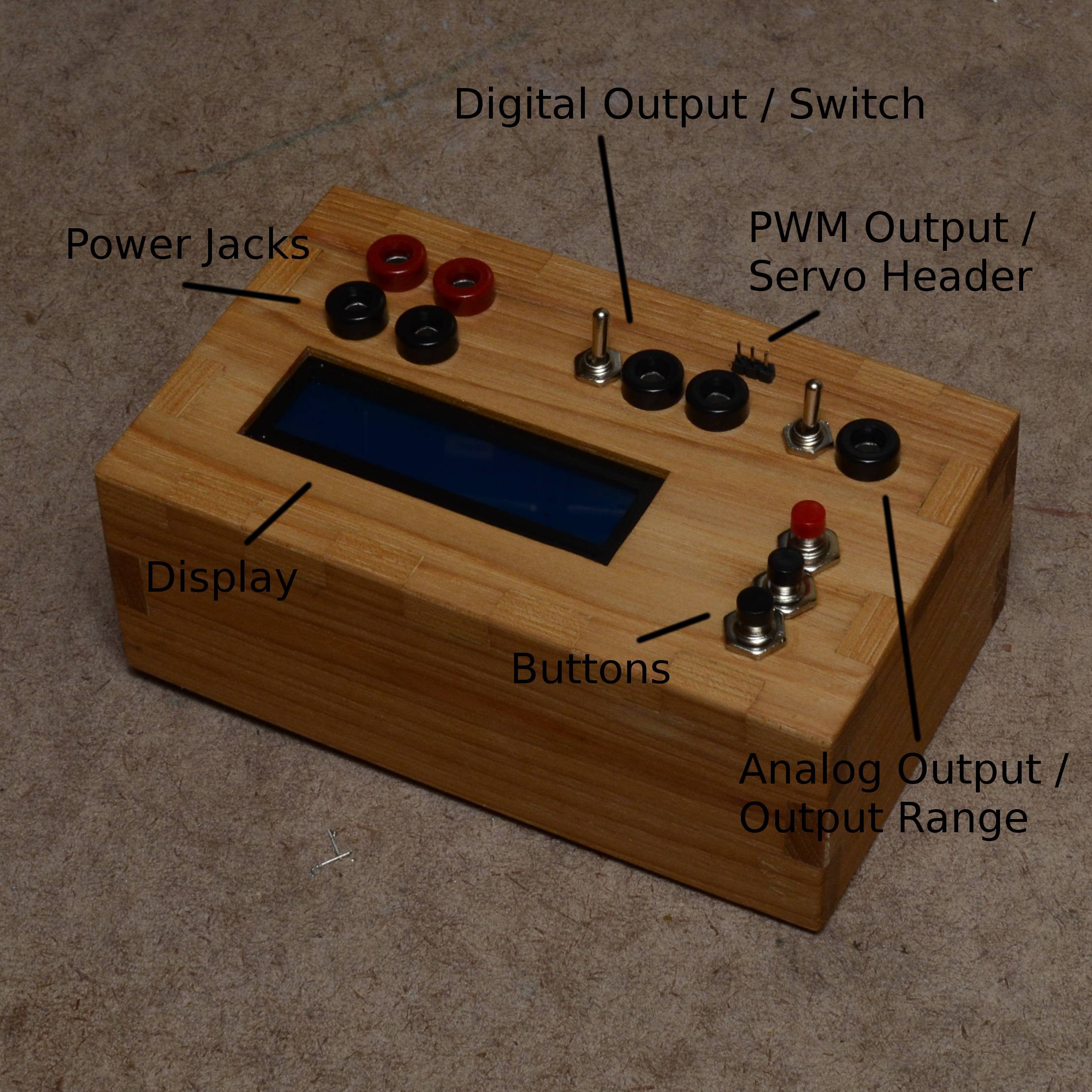
01/31/2015 at 04:52 • 0 commentsThe user interface is pretty simple:
- There are four power jacks (to get the full range of +/- 5v output on the digital signal, you should run it with a dual supply of something between +/- 6v to +/- 12v). The second ground port allows you to chain to a breadboard in case your power supply does not have multiple ground ports (mine does not).
- There are three outputs: digital, PWM, and analog. The digital output is for the fast and slow square waves. The PWM output (and its accompanying servo header) are for the servo test mode (and eventually will be for the general PWM mode, when I get around to programming it). The analog output is for the various analog waveforms.
- There are two switches. The one beside the digital output enables or disables the opamp buffer for the digital signal. (At least with the op amp that I am using, you get a lot of slew if the frequency is faster than about 10kHz.) The switch beside the analog output changes the waveform range from 0 - 5v to -5 - 5v.
- The red button is 'Mode'. Use it to switch between the various waveform options. Hold it down to start waveform generation, and hold it down again to stop waveform generation. You cannot switch to another waveform while the current one is running.
- The other two buttons change the frequency up and down. Hold them down to go faster. You can change frequencies while the waveform is active, and the change takes effect immediately.
![]()
-
A few feature changes
01/30/2015 at 23:49 • 0 commentsOver the last couple of days, I have made a bunch of enhancements to this project:
- Added a three pin header to the front of the box (right over top of the PWM banana plug output) so that you can plug a servo directly into the function generator for testing.
- Added a Square (Slow) digital mode to complement the Square (Fast) mode. The slow mode uses the same digital output that the fast one does, but is 1/256 the frequency. (The high speed square starts at 10MHz and goes down to 39.062kHz; the slow square starts at 39.062kHz and goes down to 152Hz). These two modes are meant for very high accuracy square waveforms.
- Renamed the DDS Square wave to "Square (Analog)" to differentiate it from the other two digital square outputs.
- Add protection diodes to prevent issues from plugging in the power supply backwards
- Fix some UI bugs (incrementing speed when holding buttons, garbage chars on the LCD, etc)
- Shaved a few CPU cycles off of TIMER1_OVF ISR by using GPIOR2 instead of push / pop for saving SREG
- Implemented TIMER1_COMPA in assembly so that we don't need to do the standard push register preamble (play safe, kids!)
I still need to figure out a good way to label the input / output jacks. I am thinking about cutout vinyl letters (think custom stickers), but am open to suggestions. (My first choice would have been a laser cut / etched box, but having it done as a service costs too much and obtaining my own laser cutter is even more expensive. Eventually I can see myself going this route, but not in the near future). Any suggestions on other options would be most appreciated. -
Magic Smoke
01/30/2015 at 01:48 • 0 commentsWho'd have thunk it... if you plug your +/- 12v supply in backwards, the magic smoke gets out of the op amp!
I am lucky to not have lost other components (most notably the LDO regulator or the already-damaged AVR that I wanted to try using rather than throw it away). I have now added some diodes on the +/- input lines to protect against reverse polarity supply.
(Edit: turns out that it did destroy the LDO as well, it just took a bit longer until it completely gave up the ghost. The AVR is still hanging in there, though...)
I have some different colored cables on order, so hopefully this won't happen again. :-)
-
Breadboard Video
01/29/2015 at 21:04 • 0 commentsHere's a video of the breadboard prototype, prior to moving it to a perf board.
-
Initial Commit
01/28/2015 at 23:47 • 0 commentsFirst project log... not much to say here. I have finished the breadboard prototyping, and all looks good. I am currently in the process of moving to perfboard and making an enclosure on the scroll saw. Pictures, schematics, and code will be forthcoming as soon as I get things organized.
Please stand by!
Function Generator
Simple function generator using an AVR, built from parts I have lying around