One month is a long time when you are waiting for boards to arrive!
As mentioned earlier, my PCBs are ordered and have been shipped a couple weeks ago. I estimate they will arrive in early May. Free shipping from China is slow, and I am too cheap to pay for faster shipping. :-(

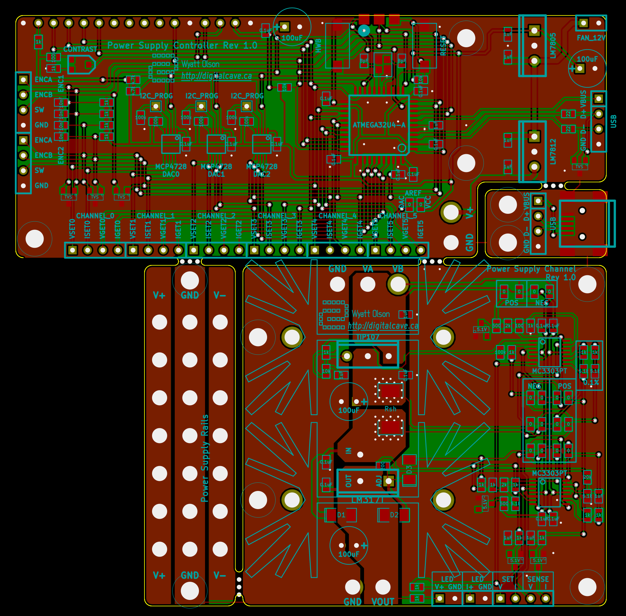
The boards are shown again here... the board with the heat sinks will be used multiple times (once per channel, so I will be using 4 myself), while the other sections will be used only once (unless I can figure out some alternate use for them).
Furthermore, I am somewhat confident that the PSU channel board can also be used as a dummy load if you skip populating the regulator + headsink, and just short out the IN and OUT lines on the regulator chip. This needs to be verified still, though.
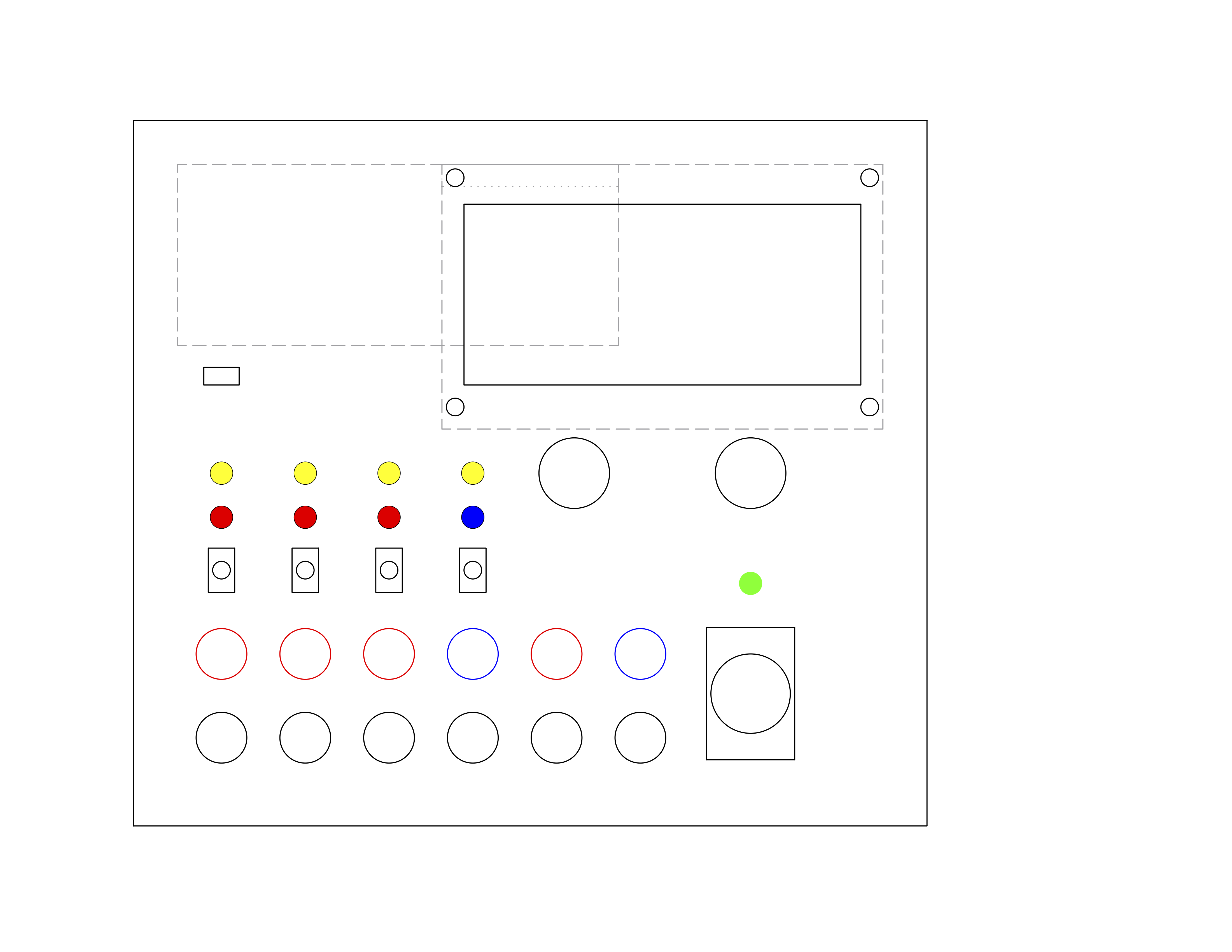
In the mean time I have been planning the enclosure. The faceplate will be brushed aluminum, and will look something like this:

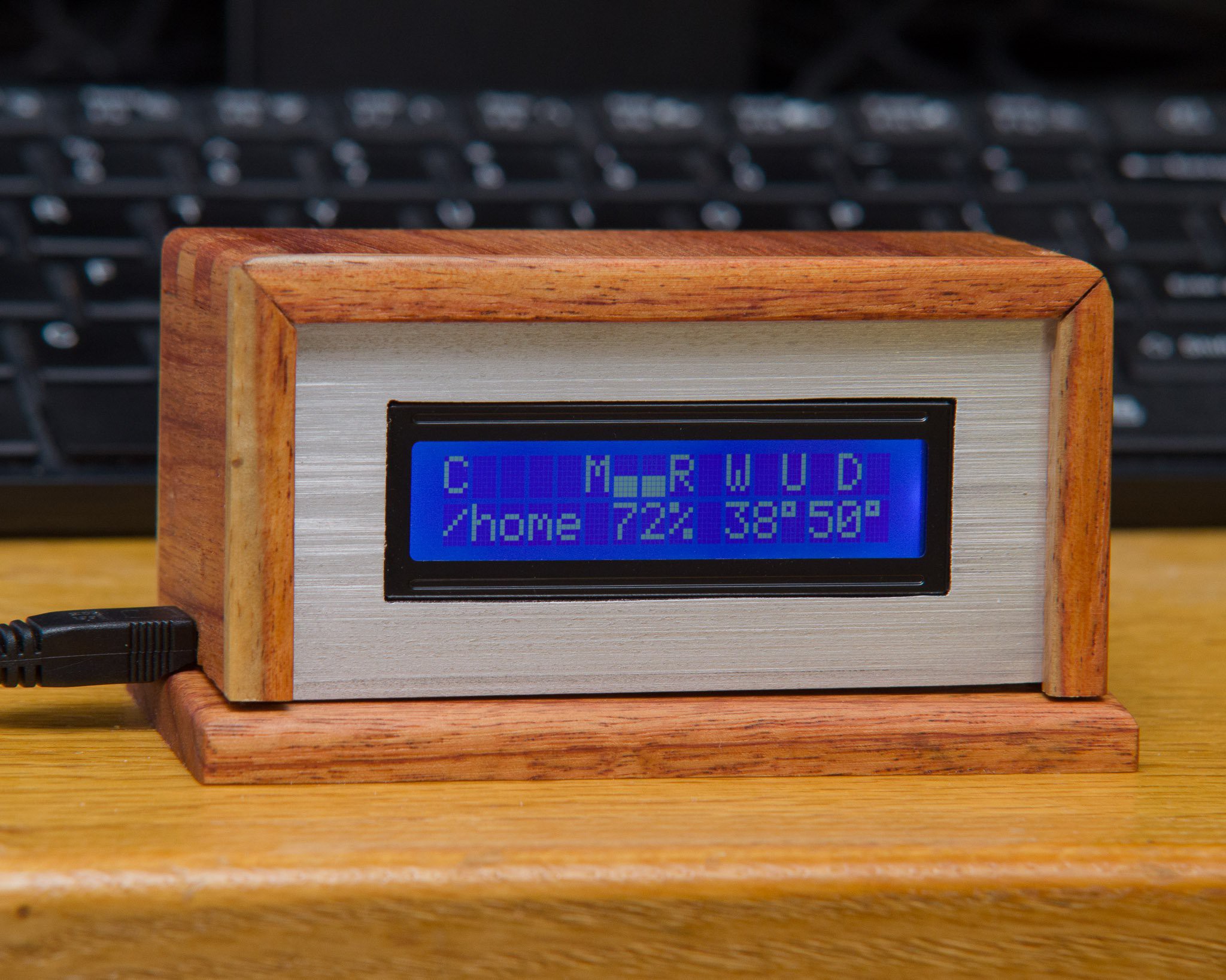
The entire enclosure will be made of wood (with aluminum front and back plates), with an overall look similar to my resource monitor:

 The Big One
Discussions
Become a Hackaday.io Member
Create an account to leave a comment. Already have an account? Log In.
The channel output config consists of 4 analog values. The SET values are supplied by the DACs on the controller, and the GET values are generated from the channel hardware and pass the actual values back to ADCs on the controller. See the schematic at https: //cdn.hackaday.io/images/9978061434596733221.png for more details.
Cheers
Are you sure? yes | no
Hi, i'm wondering how the switches are wired up. Are they just between V-out and the plug or are they wired an other way?
Are you sure? yes | no
Are you talking about the encoder switches?
These are done in the normal fashion with a pullup on the SW pin, and the switch completing the circuit to ground.
Cheers
Are you sure? yes | no
I ment the channel switches enabling the channel output (that is at least the function they are I guess).
Are you sure? yes | no