 The Big One
My boards arrived today, so when I got home from work I started to solder one channel up to see if things worked.
Spoiler alert: it works!
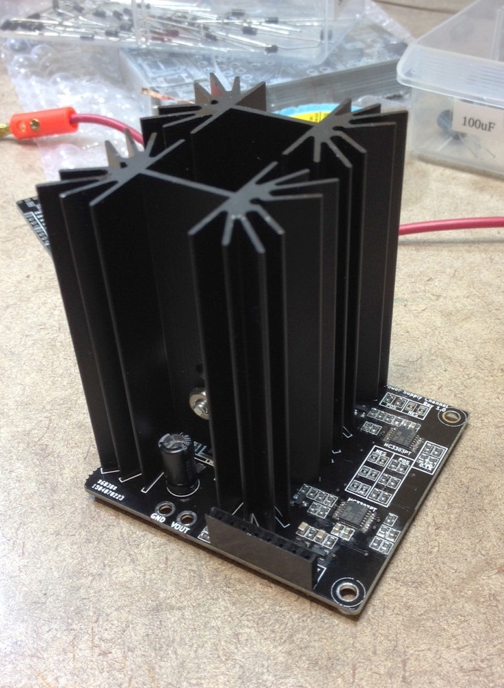
It took a couple of tries. Reflow soldering TSSOP chips is hard, and I still have not got the hang of it - there always seems to be one or two solder bridges hanging around, which are very hard to see even with a loupe. Also, I don't have the SMD schottkey diodes which I had planned on using, so I had to substitute a through hole diode with the leads trimmed to be a couple of mm in length.
So far I have found only one error on the board: the D3 diode is reversed. It shows the polarity pointing towards the bottom of the board, but it should be the other way. Sorry!
Below is a quick video showing off the beautiful soldered board in action... it was unrehearsed and done in one take, and hence rambles a bit, but hopefully it gives you an idea of how things look and work. Enjoy!
Discussions
Become a Hackaday.io Member
Create an account to leave a comment. Already have an account? Log In.
This is looking really good. Nice to see the progress.
Are you sure? yes | no
Great news mate! Did you say in the video does the supply voltage drop when in current limiting?
Are you sure? yes | no
Correct, when current limiting kicks in it drops the voltage such that the current does not exceed the set point.
Are you sure? yes | no