The Big One
-
Software Changes
08/30/2019 at 22:25 • 4 commentsIn case anyone else has made one of these, I have recently made some software changes. The biggest new feature is that calibration is supported directly from the power supply - no connection to a computer needed. The reason for this is that I have had nothing but problems with the RawHID Python support on Linux and OSX; setting it up was nearly impossible, and if you did manage to get it installed (with custom compiled code) it would just segfault when you try writing stuff. After many hours of debugging it, I gave up.
In addition to adding calibration, I did some code cleanup, updated the code to use my latest build scripts and toolchain, and fixed some minor bugs that I had never bothered fixing before.
The latest code is on my github page: https://github.com/thebiguno/microcontroller-projects/tree/master/projects/power_supply/avr
-
6 Months Later...
12/24/2015 at 07:54 • 3 commentsMy power supply has been completed for about 6 months now. I cannot begin to explain how nice it is to have a real power supply; I wish that I had obtained one years ago! For anyone who is on the fence about a real power supply vs. a hacked ATX job, go for the real one, even if it costs a bit more time / money.
I find that I am using this supply all the time; just today, for instance, I was debugging a power supply issue on my Drum Master board (I have a 3.3v linear regulator which is supposed to source up to 250 mA, but which is browning out when I try to write to the SPI flash chip). By using my power supply in place of the wall wart, I was able to determine what was actually happening and how to fix it (spoiler alert: my wall wart's voltage was too high, and thus the linear regulator had to dissipate too much heat and would go into thermal shutdown). Could I have figured this out without an adjustable power supply with actual current readings? Of course. But it would have been harder.
Anyway, 6 months on, and I am loving it.
Merry Christmas, all!
-
Semifinals Video Added
09/17/2015 at 01:46 • 0 commentsI have just added the Hackaday Prize Semifinalist Video. This shows the power supply in action, powering another WIP project that I am currently working on. I also discuss some of the other features (USB calibration and control, etc) and some of the shortcomings of the design (requires a dual supply; difficult to isolate).
-
Free Adjustable Dummy Load
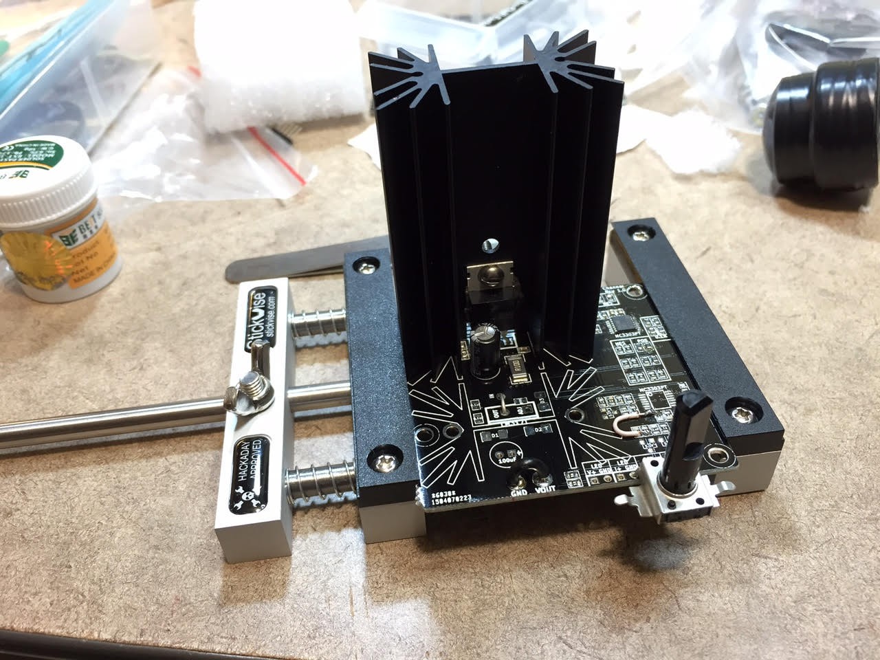
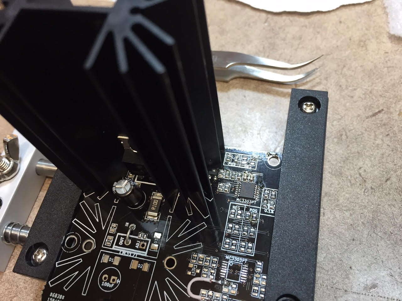
08/23/2015 at 01:24 • 2 commentsFor those who have ordered the PCBs, you probably have a bunch of boards left over. Rather than just let them accumulate dust in your desk, you can use one of the channels as an adjustable dummy load. It's not the best dummy load, as it was not designed specifically for it, but it does the job decently.
Basically, you just need to populate the top of the board and add a few jumper wires. Place a jumper between OUT and IN on the voltage regulator chip, and between GND and VOUT at the very bottom. Just as with the power supply channel, you can control the current by applying a voltage on the I SET pin. The lower the voltage the less current will pass. If you use the recommended component values, it will allow for 5v I Set = 5A current. I put a potentiometer on this pin to let me easily control it, but you could also use a DAC or something.
![]()
![]()
To use it, you plug in the power supply under test to VA / GND, and supply a negative voltage (I use one equal to VA in magnitude) to VB. (Yeah, it's annoying that you need to provide a dual supply for a dummy load... but that's the way I designed the power supply.)
If you wanted to improve on things a bit, you could not solder on the top 0 ohm resistors, and instead connect the logic supply (+/-/GND) to those pads; you can then connect the power supply under load to the VA / GND pins. This should give better results since the logic supply is separate from the main supply. Take a look at the PCB layout to see exactly where to solder things...
Enjoy!
-
Other Makers
08/18/2015 at 15:00 • 1 commentTo my knowledge there are currently 4 people attempting to make this (at least I can see that 4 people have ordered the Rev 1.0 boards from DirtyPCBs). I have no idea who (if anyone) has attempted to use the new Rev 1.1 gerbers I have posted a few days ago.
Please let me know if / when you get this working, I would be very interested to see other's versions (especially if you do your own enclosures, but even if you just do it as a bare PCB I would love to see it!)
Cheers
-
Rev 1.1 Gerbers
08/13/2015 at 16:06 • 0 commentsIf you want to make this yourself, please use the Rev 1.1 gerbers, available on github. This fixes the issues in the Rev 1.0 board, and should make for a smoother experience overall.
-
Project Completed
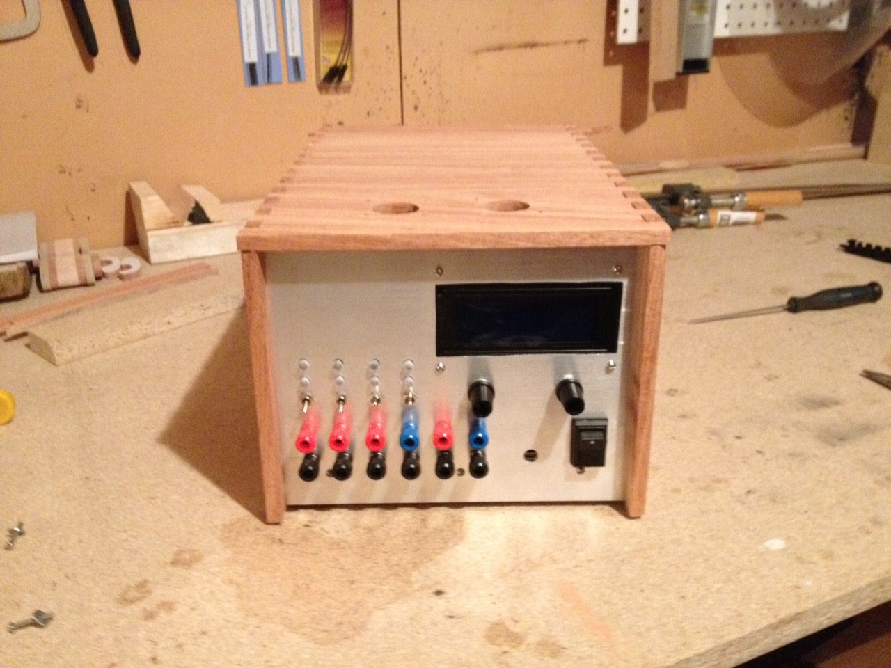
06/18/2015 at 03:32 • 2 commentsYesterday I put the final touches on the wooden case. Everything has come together wonderfully, and just under 6 months of work has paid off:
![]()
![]()
I have made a video demonstrating some of the features. It is a bit long (about 9 minutes), but hopefully will be interesting to anyone who wants to make their own (or even just see what this one does):
-
Almost There...
06/16/2015 at 15:21 • 0 commentsThe past week or two has been very busy and productive, although I have not posted many updates. Most of the work has been related to the case.
I have always planned for the case to be made of wood. I had a rough idea of the design (two sides + top, joined with finger joints, sliding down over the aluminum faceplates and secured with screws on the sides). In order to do this, though, I needed to make some tools... read more for details and to see all sorts of pictures!
In the past I have made finger joints on my scroll saw. It works, but it is slow and error prone. I have had a router for years, but did not have a decent router table, so I was limited in the jigs that I could make.
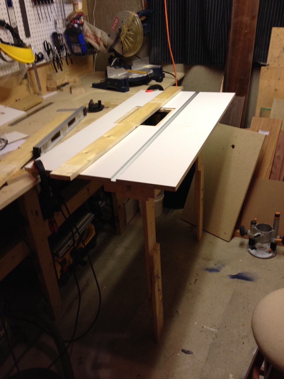
So, first step was to build a router table.
I based my design loosely on this design. I skimped on some parts (e.g. I used 1x4's for the legs, etc), but it turned out to be quite nice. I put a mitre slot from Lee Valley Tools into the table to allow for jigs.
![]()
![]()
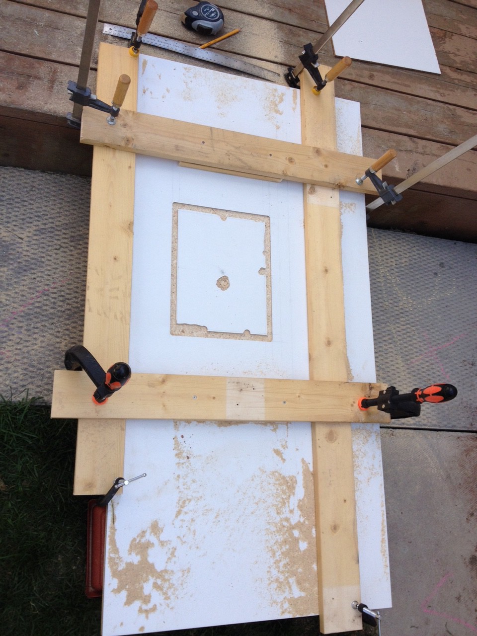
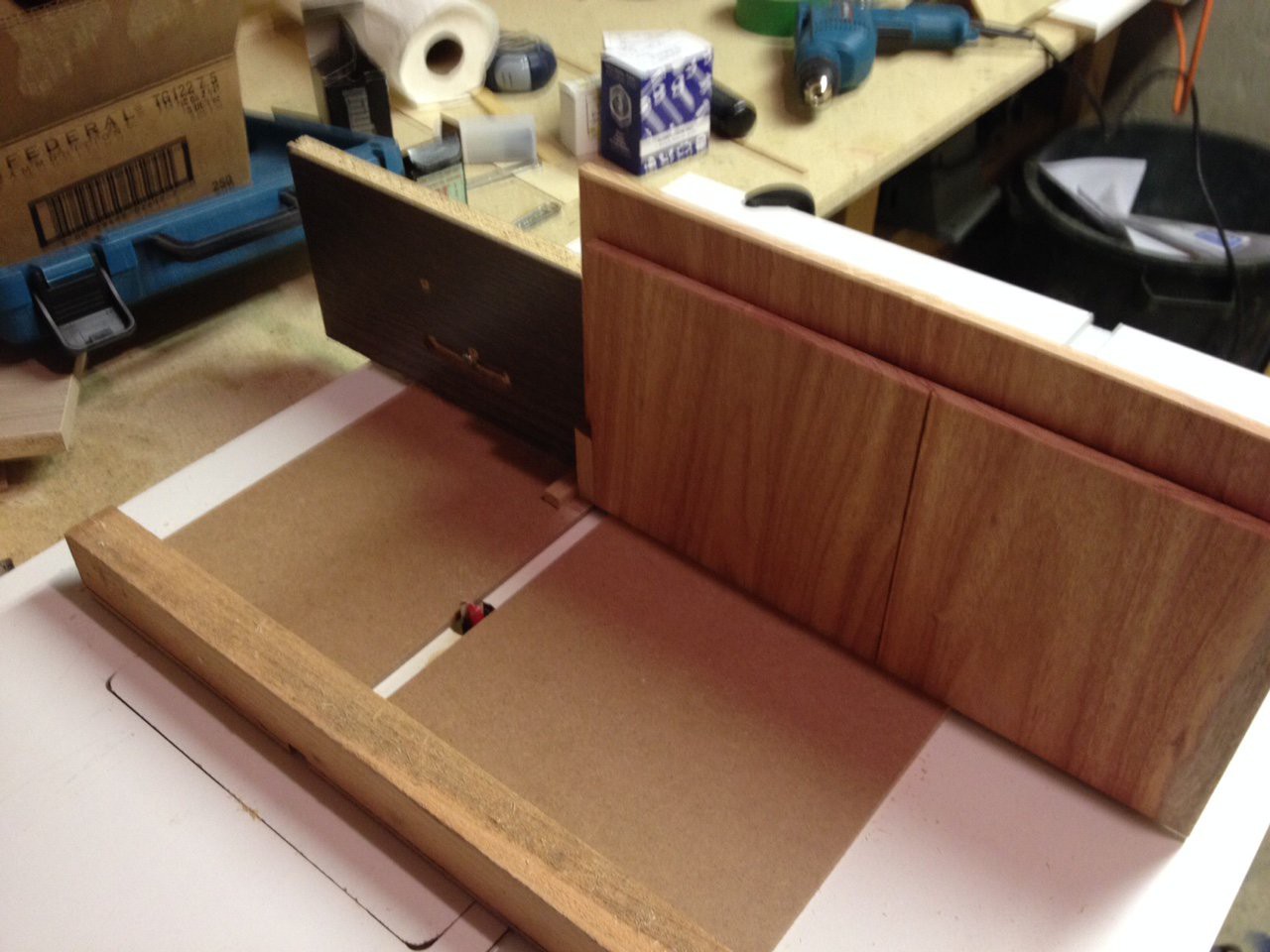
Next I made a finger joint jig. I based my design off of these plans (even though they were designed for the table saw, the concept is the same)
I don't have pictures of the actual cutting (I don't have three hands, although sometimes I wish I did), but here is the setup right before I turned the router on:
The cuts worked out well; both sides fit together perfectly.![]()
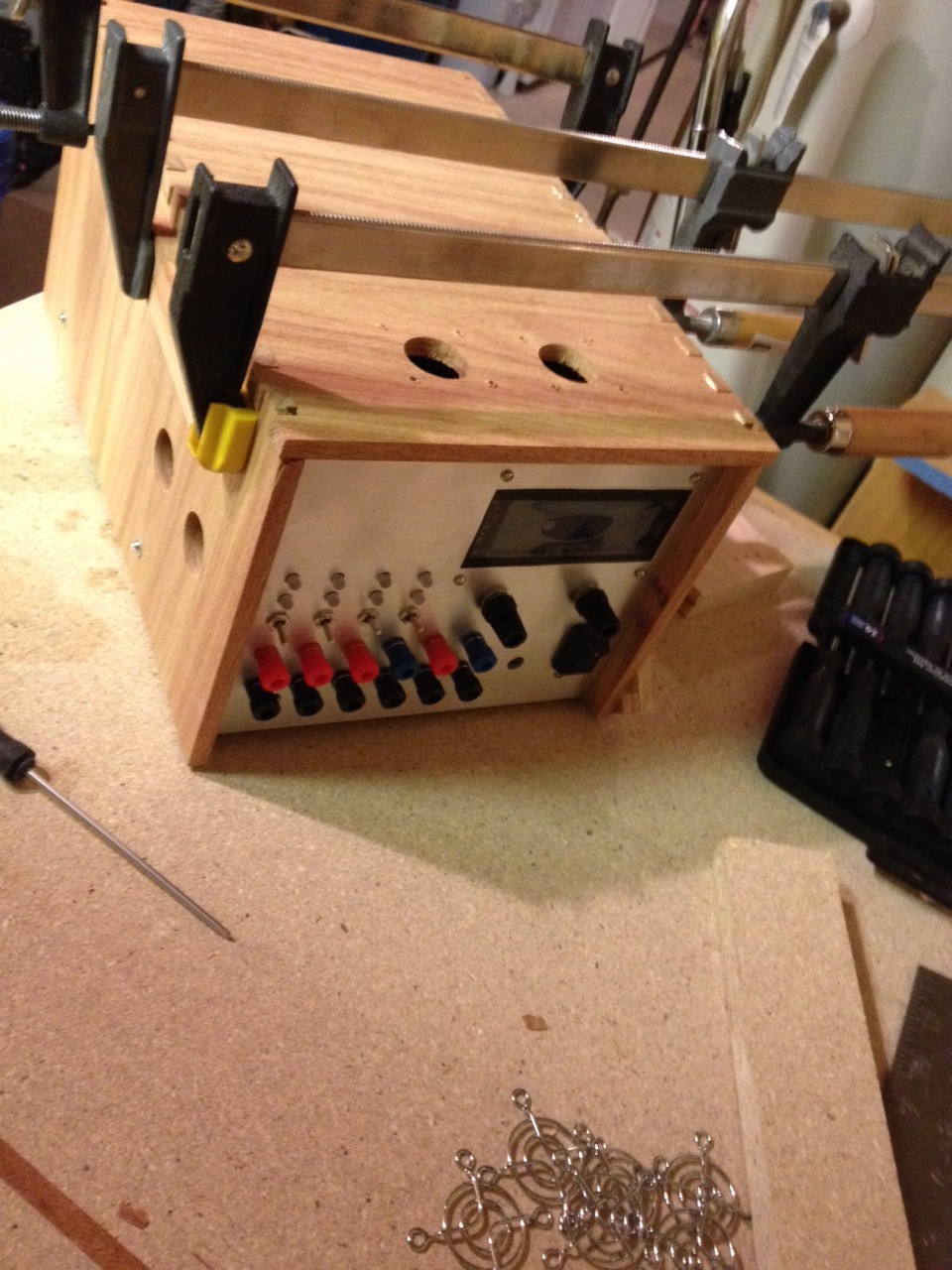
I then (over the next few days) cut some air outflow holes in the sides + top, epoxied nuts to angle brackets so that the sides can be secured to the bottom, cut slits in the grooves + top on the table saw for the aluminum to slip into, and finally, last night, glued everything together:
![]()
![]()
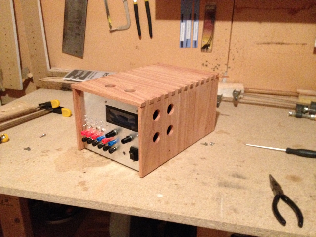
Over the next few days I will be sanding, staining, and attaching the fan grills to the outflow holes. I am considering adding some handles as well, although I may not do that (it is not meant to be portable, and will likely spend most of its existence on the same shelf in my electronics area). I also may make a wooden border for the screen (I didn't get the aluminum cuts quite as nice as I had hoped to...)![]()
Cheers
-
First Real-World Use
06/10/2015 at 05:04 • 0 commentsEven though it is not quite finished, I used my power supply for the first time today (the first time for a real project, not just testing the supply itself). I was powering on an H-Bridge circuit for the first time, and wanted to a) ensure that it didn't suck too much current if there was a bug, b) see how much current was being drawn. It performed both tasks flawlessly (and for the record, there was in fact a problem with the H-Bridge board, so current limiting came in handy!
-
Multi Point Calibration Working
06/09/2015 at 16:56 • 0 commentsOver the weekend I have implemented multi point calibration. I currently use 8 calibration points, which seems to work just fine. I use linear interpolation to get calibration values between the calibration points. Testing shows that things are working quite well. Current limiting is working, and accurate down to less than 20mA (I can even plug an LED directly into the power supply outputs without it blowing up!)
I also added the ability to set startup voltage / current limiting on a per-channel basis. This is configured via the calibration script (run on the computer, talking to the power supply over USB Raw HID).
I will post a demo video when I get the chance, although that may not be for a few days given my workload right now...
Bench Power Supply
Designing an open source, modular bench power supply to rule them all.