Close
0%
0%

sdramThing4.5 "Logic Analyzer"

An AVR, 128MB SDRAM DIMM, old laptop LCD, and a handful of TTL chips -- 30+MS/s 32-channel logic-analyzer interface for an analog 'scope

Similar projects worth following
This is a Sample/Repeat "Logic Analyzer" with up to 32 channels at 30+MS/s, each.

After sampling, the data is repeated e.g. to an oscilloscope for viewing.
Two channels of the sampled data are displayed as red and green in "rasta"(raster) fashion on an LCD display.
Cursors (in blue) are used to select a window for repeating, allowing for bright 'scope traces.

** 'sdramThing' **
By connecting an SDRAM's Command and Address signals back to its Data signals it's possible to create (what I call) a "free-running SDRAM" that can do quite a bit with little-to-no MCU overhead.

sdramThing4.5 makes it possible to free-run the SDRAM at speeds far-greater than the processor (looking toward 133MHz!).
Once it's loaded with the initial set of commands, it can be physically disconnected from the MCU and continue doing its thing.

(See the "Deprocessorization video" wherein I remove the processor from its socket while the SDRAM continues sampling, repeating, and refreshing the LCD!)

sdramThing was recently featured on the Hackaday Blog! Thanks Al Williams!

SDRAM Logic Analyzer Uses An AVR And A Dirty Trick | Hackaday

Note that sdramThing4.5 (this project) has pretty much reached an end. The next phase is more of a peripheral--using these same "dirty tricks"--which can be connected to any uC, SBC, or even a PC's slow parallel port. Check it out at #sdramThingZero - 133MS/s 32-bit Logic Analyzer

(which was also recently-featured on the blog! Thanks Benchoff!)


For an electrically much-simpler circuit to drive an old laptop LCD display using just an AVR and two TTL chips, see: avr-lvds-lcd (it can even be done with an 8-pin ATtiny85 with only 512B of RAM!).
I should also give some credit to this project: http://tinyvga.com/avr-sdram-vga for introducing me to SDRAM's Burst-Mode which sdramThing relies on *heavily*.

This description is quite a bit outdated... I'm at sdramThing4.5, and many of these notes are from 3.0... Beware ;)


What is sdramThing?

This project (sdramThing3.5, now) implements a logic-analyzer interface for an analog oscilloscope.

It works by sampling data at high-speed, then repeating that same data quickly-enough that it can be seen as a bright steady trace on an analog oscilloscope.

Currently, it samples and repeats at 20MS/s. 64MB of a 128MB SDRAM DIMM is dedicated to storing these samples, and it has the ability to sample/repeat 32 bits simultaneously (2MSamples per input). Two of these channels are output as Red and Green on an old laptop display.

Cursors are used to select and repeat only the interesting portion of the sample, triggering the oscilloscope at the beginning of the selected-data, then repeating the selected samples several times. This back-to-back repeating of short-duration samples allows for bright traces on a 'scope, even at high "zoom".

This sample/repeat process is made-possible by sdramThing's "Free-Running" mode. This mode takes advantage of the SDRAM's synchronous nature to allow it to control itself. (See below, for more details).

In Progress:

The particular project that inspired this project has requirements outside sdramThing3.0's ability. My data-source appears to have a clock-rate of 25MHz, while sdramThing3.0 has a sample-rate limited to the AVR's clock-speed of 20MHz.

Thus, I've revisited looking into making use of the SDRAM's ability to run at speeds much faster than my AVR (thus: sdramThing3.5).

It's entirely plausible, with a bit of work, to get sampling up to (and exceeding) the SDRAM's rated clock-speed of 133MHz (133MS/s). But currently, I'll be happy to get it working at 40MS/s, as my attempts at decoupling the SDRAM clock from the AVR clock have been slow-in-progress.

The current status, as has been for a while: I have designed and soldered-up the "one-shot" circuitry necessary for decoupling the clocks, but, ironically, it's not even working with that circuitry in "bypass" mode. I've been fighting this for a while, now. Finally, I've reimplemented the ability for the AVR to read-back the data it wrote to the SDRAM, so maybe I'll get somewhere soon :)

Details (a tiny bit outdated):

For more info on Free-Running SDRAM and sdramThing3.0, click here.

As I'm refreshing my memory on how it works, so as to fix some bugs and improve functionality, I'll probably throw some relevant notes here, both for you and for me ;)

sdramThing3.0 makes use of two groups of memory on a typical DIMM. The "Free-Runner's" memory is loaded with all the commands which are fed back to both devices' command/address-inputs. Thus, the SDRAM actually sends commands to itself, and runs "free" from (independent of) external control (like the AVR).

The "Side-Kick" has two modes: Write and Read, which correspond to the "logic analyzer's" Sample and Repeat.
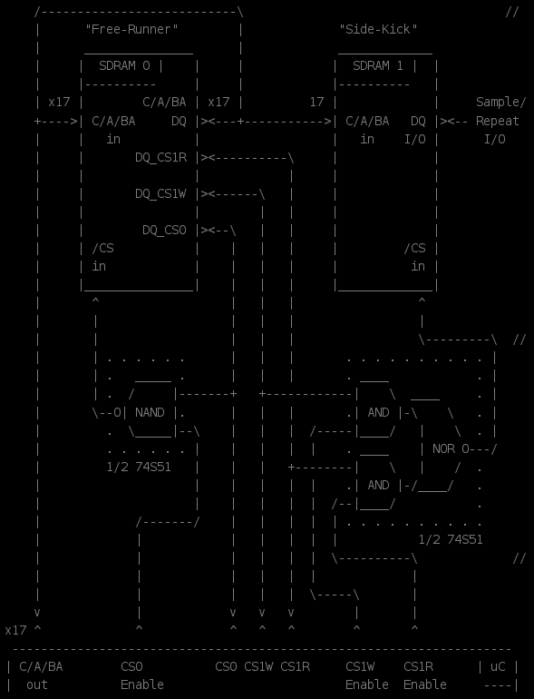
Multiplexing-logic allows for selecting the mode... The Free-Runner is loaded with commands for both Read and Write for the Side-Kick. Both commands are always output. The logic enables the read commands for repeat-mode, and enables the write commands for...

Read more »

64mb_x4x8x16_sdram.pdf

Micron SDRAM chip Datasheet: MT48LC8M8A2 pretty much general-purpose for most SDRAM chips.

Adobe Portable Document Format - 5.99 MB - 07/23/2016 at 21:59

Preview

unb_001 SDR.pdf

Intel’s PC SDRAM UNBUFFERED DIMM SPECIFICATION Rev 1.0 Pinouts, etc for DIMMs (Be sure to look at section 5. Also browse my gallery for a pinout I drew-up)

Adobe Portable Document Format - 438.95 kB - 07/23/2016 at 21:55

Preview

  • 1 × Micron SDRAM chip Datasheet: MT48LC8M8A2 pretty much general-purpose for most SDRAM chips...
  • 1 × Intel’s PC SDRAM UNBUFFERED DIMM SPECIFICATION Rev 1.0 Pinouts, etc for DIMMs

  • SDRAM/DIMM Specs and sTZ

    Eric Hertz07/23/2016 at 22:08 0 comments

    If you haven't looked already, #sdramThingZero - 133MS/s 32-bit Logic Analyzer is pretty much the new project... turning sdramThing into a bit more of a logic-analyzer peripheral to be connected to any "host", rather than an entire system in and of itself... I intend to keep it as "transparent" as possible, e.g. using only 74xxx00-series chips, such that it could be easily-understood/reproduced as well as implemented on most any host (e.g. a Raspberry Pi through Python, or even a Commodore 64 through BASIC).

    So, that'll probably be a good place to get any new info I make available on how to work with SDRAM. (Oh, and Thanks @Benchoff, for the blog-writeup on that!)

    I've also added two of my go-to resources in the "Files" section of both projects... DIMM pinouts/layouts as well as SDRAM pinouts/commands, etc.

  • Single Instruction Computer - "ByteByteJump"

    Eric Hertz06/13/2016 at 06:22 0 comments

    I think something like this might be downright almost completely-doable with the state-machine already built-into SDRAM...

    http://hackaday.com/2016/06/11/designing-a-single-instruction-computer/

    I haven't looked into the details too thoroughly, I think the idea is to basically implement whatever instructions you wish to use as look-up-tables in memory. Well, hey, here's a shitton of memory ;) Then there's something about jumping, which sdramThing is *really* good at...

    Of course, loading those look-up-tables is another thing entirely... FLASH makes more sense, but generally slower and smaller (in the parallel-interface format).

    It's a curiosity I might revisit... (in fact, by writing this, I am already revisiting the idea of turning sdramThing into a CPU... something I vaguely thought of a while-back... here's something suggesting it's not only possible, but even implemented in different forms)

  • Did planning toward ddrThing from the start bite me in the a** AGAIN?!

    Eric Hertz03/19/2016 at 11:55 0 comments

    It almost seems as though the SDRAM clock could be strobed whenever I so-desire... which would *REALLY* simplify the danged thing. Could probably get rid of one-shots altogether, dagnabbit!

    Read more »

  • Blog Mention! + sdramThingZero

    Eric Hertz03/15/2016 at 23:46 2 comments

    Alright, first-off... a Major Thank You to @Al Williams

    (I think I got it right, this time ;))

    For The blog write-up to rule them all...

    (Or, maybe not "them all" as in all-blog-write-ups in general, but as in a write-up [about sdramThing] to rule all write-ups about sdramThing that've been attempted (as far as I'm aware, having been the only other write-up-attempter, as far as I'm aware, and having been exceedingly wordy and likely quite confusing in all cases. That is to say, thanks for coming up with an explanation that actually makes sense, without my incessant rambling! And for attracting attention by so many, including those who understand the odd-hackery I'm quite proud of that went into this goofball-concept! Nevermind the slew of ideas-generated and resources-mentioned in the comments-section... Wait, what? I'd gotten used to knowing the HaD Blog for a different type of commentator! But this is pretty cool, too.).

    So, now... Per this project's previous log-entry and despite my prior cynicism, and with a lot of great insight from others (see "previous log-entry)"... I think it's plausible, nay probable, to create #sdramThingZero - 133MS/s 32-bit Logic Analyzer... a new, GPIO-based peripheral-ish to connect to nearly anything with GPIOs (especially, maybe, a PiZero, with its display/HID abilities and huge processing-power!) based on little more than an SDRAM DIMM and some glue-logic. Possibly, probably-maybe--based on some inspiration from the blog's unusually-insightful commentators--some of this project's necessary-glue-logic (as well, maybe, as that necessary for some features newly-inspired from others amongst the afore-mentioned commentators) might actually be implementable within the very SDRAM that needs the glue-logic in the first place.

    PARSE THAT!

    Suffice to say... We're talking... plausibly, relieving much of the glue-logic and latches necessary for e.g. "one-shots"... We're talking, plausibly, adding new features such as complex-triggering (e.g. via serial/parallel data-pattern-matching)... and, quite-plausibly, doing-so with little more circuitry-wise than what's already available on the SDRAM DIMM, [redundantly] already...

    This is getting dense and intense... but is a challenge, at least mental, that seems, at least to me, worthy of at least as much time as many of the mental "challenges" many of us convince ourselves are necessary on a daily-basis.

    So... If you dig what you've seen, here, and are interested in seeing it branch-off in a newly largely-group-inspired direction that could quite-plausibly be not only usable/useful, but also repeatable with little more than a Single-Board-Computer (or microcontroller, plausibly even a PC's parallel-port) of your choosing, a PCB-order, and an old DIMM likely already in your aging collection, consider visiting/following (and even joining?) #sdramThingZero - 133MS/s 32-bit Logic Analyzer, in addition to this one!

    This'll be an entirely new, and completely un-pre-thought-out path for me, as far as projects go, so... who knows what'll happen... It's plausible it'll be a *very* slow process. (It took four-five years to get to this point). It's also entirely plausible everything I'm envisioning fitting together like puzzle-pieces these past few hours is nothing more than too much coffee and delusions of grandeur. But do follow!

    Or, if you find yourself creating something from any of these ideas, I'd love to hear about/link it.

    Thanks again, Al Williams, for the write-up/attention!

    And thanks to everyone who's given great ideas already... Let's keep 'em coming till my brain explodes(?)!

    (If you dig it... I hate to ask... but I could also really use some moolah, in general these days, but this month especially.)

  • CKE? - "Well... shit."

    Eric Hertz03/09/2016 at 13:07 1 comment

    Thoughts have been bouncing around regarding sdramThing over the past few months... If you hadn't noticed, it's been on hold for quite some time... its original motive-for-revisit which advanced it from 2.0 to 4.5 was actually due to my plans to build a CNC machine (maybe a PCB-router)... I didn't have any motor-driver chips, at the time, so was planning to use sdramThing as a logic-analyzer to figure out what signals to send to a motor-driver I found in an old printer. Whew. I wasn't able to get it fast enough to read those signals (whoa, 18+bit SPI at > 30MHz?!), probably due to the ratsnest of wires... But I did eventually get some motor-driver chips, and went on with my original goal of working toward the CNC machine... So, sdramThing reached a pretty decent stopping-point. Definitely functional, definitely usable, proof-of-concept regarding one-shots and separating the uC clock from the SDRAM's clock definitely proven...

    But, it's been bouncing-'round the ol' noggin' again recently... thanks in part to interest from folks like @James Newton and @frankstripod. I had it in my mind that maybe, even, it could be run from a PiZero (inspired by the Adafruit PiZero contest at: https://hackaday.io/contest/9326-adafruit-pi-zero-contest, and some insight in the comments there from @nistvan.86). Running on a more-powerful processor like that would open up new doors as far as actually *processing* the data, nevermind displaying it... Got some excellent information on just how different the GPIOs on a PiZero are than those on an AVR, from @usedbytes and @Vikas V, and some others.

    As it stands, sdramThing4.5 requires *precision* timing on the part of the microcontroller. For the AVR this is (comparatively) easy. Using assembly, it's possible to determine *exactly* how many CPU-cycles occur between, say, the rising-edge and falling-edge on a pin. Apparently that's not exactly possible (or at least not as easy) with more "sophisticated" processors that use things like cache, branch-prediction, MMUs, Flash-based execution vs. executing from RAM, etc. (check out some very informative commentary/explanations by @usedbytes at #Operation: Try the Pi).

    SO.

    There seems to be a multitude of strikes against porting sdramThing to other architectures... Oh, the other was... what about using this as an oscilloscope-shield for arduinos...? I'm not too familiar with Arduino and its libraries, so I can't vouch for what I'm about to say, but it seems like precision-timing to the extent of using Assembly, shutting off the system's timer-interrupts during the five minutes it takes to "boot" the SDRAM, and whatnot, maybe not so Arduino-friendly.

    So, now, I guess there's a theme... it took me a while to piece-together. But basically: can this be accomplished on other systems, especially those where timing is imprecise...?

    One thought was to go back to (or start a new branch from) sdramThing1.0, wherein this level of precision-timing is unnecessary. sdramThing1.0, though, uses *quite a few* pins... Surely more than available GPIOs on a RPi. So, then, latches and buffers... and now we're at the point where it'll take multiple cycles just to load a single data-byte to the SDRAM.

    So, was about to count-out all the necessary pins, see if there's a way to reduce the pin-count, or at least see whether *either* system could possibly fit in so few GPIOs (FYI, sdramThing4.5 requires at least 23 GPIOs, does the Pi even provide that many?!)...

    But then it occurred to me... CKE, the Clock-Enable input. I never used this pin for anything before... For the most-part it seems like it's intended for putting the SDRAM in "sleep" mode, but it appears that it *can* actually be used to essentially halt the SDRAM for individual clock-cycles. Huh!

    So, this whole time, instead of using *multiple* one-shot circuits, I might've been able to use *just one* attached to CKE! Further, doing-so might mean that precision timing is completely unnecessary. Just set-up the command with CKE disabled,...

    Read more »

  • It may not be as niche as I thought...

    Eric Hertz03/09/2016 at 07:48 0 comments

    10/27/23: This has been sitting as an unfinished draft since 3/9/16... 7 years. heh.

    Herein, it seems is the beginnings of #sdramThingZero - 133MS/s 32-bit Logic Analyzer 


    ...........

    Thanks to @Vikas V, @usedbytes, @James Newton, @frankstripod, and a few others I'm sorry I'm forgetting by-name, for bringing to light that this project may not be as... obscure...? niche...? or something... as I had thought!

    In this era of *really fast* single-board computers, and 100+MHz microcontrollers like the ARM and PIC32 (which I'm becoming familiar with)... nevermind BeagleBones, Raspberry Pis, etc. with built-in memories larger than most SDRAM DIMMs... It was easy to think "sdramThing is really just a hack to make a lowly 8-bit uC do way more than might be expected"...

    That's true, actually... I kinda went into it with that goal in mind... Really, the main goal was to see whether the SDRAM could control itself, and what could be done by doing-so... in which case the lowly-AVR is merely an initializer, or a boot-strapping device...?

    I kinda figured maybe others might see value I hadn't predicted in this "Free-Running Mode" and take it on in their own projects, now that things like Arduino are accessible to the creative-masses beyond just engineers. But, I did kinda figure it would be a bit niche... It has its limitations, for sure... It's not quite the same as merely plugging a huge amount of RAM onto a 'lowly-AVR,' usable for any purpose one might need a huge amount of RAM for...

    Instead, "Free-Running" SDRAM is really best-suited for huge(/fast) *bursts* of raw data I/O... and my creativity-level hasn't really thought of much beyond either a video-framebuffer (and a stationary-image, at that), a logic-analyzer, or an oscilloscope (being like a logic-analyzer with an ADC attached to its inputs).

    I had some other non-raw-burst ideas that are a bit "out there," including things like creating complicated jump-tables that could plausibly turn Free-Running SDRAM into something a bit like a processor. E.G. certain "pages" in the memory could be certain functions, a "NOP" being the easiest, where the only thing stored in that page is a "jump" back to its beginning. A separate source (e.g. a microcontroller, or a bit of logic combined with a multiplexer) could reroute that "jump" command to another location entirely... Anyways, it's totally vague and a bit "out there".

    Or, similarly, several separate data-bursts could be stored in different locations for different purposes. A simple example, from my experience with sdramThing, is the use of the framebuffer connected to an LVDS-LCD display. One possibility is to store the entire image-frame ALONG WITH the necessary horizontal/vertical porches and sync signals. In other words, every row of image-data *also* stores the horizontal porches. Then the entirety of the RAM is dumped sequentially. Another way of doing this would be to have one "page" (or group of pages) in memory devoted to the horizontal porches. Each row of image-data, then, would eventually jump back to this single "horizontal-porch" memory location, and an external multiplexer would reroute the "jump" at the end of the horizontal-porch to the next row of image-data. Thus, then, the source of that jump-reroute (e.g. a microcontroller) only needs to increment its address-routing bits once per row, and the entirety of the row-drawing itself is handled by the Free-Running SDRAM, alone.

    So, that thought-process could surely be extended to other things, but I've yet to think of *what* exactly... And... I digress.

    SO... new fast single-board-computers with huge amounts of RAM kinda makes sdramThing seem a bit ridiculous, even as a logic-analyzer or 'scope... BUT it appears there may still be a use...

    Apparently, from what I've read/understand, the Raspberry Pi is a great example... This guy has a ton of RAM, but that RAM is not really accessible to the outside world at a low-level, nor even through its few GPIOs and DMA. So,...

    Read more »

  • Dual-Pixel Thoughts

    Eric Hertz10/23/2015 at 07:36 0 comments

    Now that I've managed to repair a pretty-decent LCD Monitor (#Ridiculous [LCD] Display Hacks) that's been dead in my collection for nearly a decade... I'm feeling a little less stingy with the ol' 15inch monitors in my collection...

    So I've some ideas...

    One of those 15inchers is 1024x768, same as the one used in sdramThing, except that it's dual-pixel.

    What's this mean as far as sdramThing...?

    Well, it might be *difficult* to see, but it would allow for visualization of 5 of the logic-analyzer's channels rather'n 2, on the LCD.

    Currently, only two channels can be "seen" on the (single-pixel) LCD, "red" and "green." (Though, 32 channels are sampled and repeated, regardless of what can be *seen* on the LCD.).

    Why two? The LCD's "blue" "channel" is tied-together with the LCD-timing-signals which shouldn't change, regardless of sampling, so "blue" can't exactly (easily) be tied-together with the displaying of sampled data. This isn't a bad thing, though... It leaves that color/channel available for other purposes, such as the cursors... which are quite handy.

    That said... A dual-pixel display would allow for *5* channels to be viewed simultaneously on the LCD... The first two, mentioned before, "red" and "green," would be displayed in the first, third, fifth, and other "odd" columns... The remaining three would be visible in the second, fourth, and remaining "even" columns, in red, green, and blue. The cursors could remain in the odd columns...

    It's a weird concept, but not exactly useless. Weird: well, even and odd columns of pixels would be displaying different sets of samples that were all taken at the same time. The first two channels' samples in one column, the next three in the next... You can imagine how hard it would be to *see* a particular waveform/pattern in that manner. OTOH, *seeing* a waveform on this "rasta"-display is difficult anyhow. That's the whole point behind sample-and-repeat (to be fed into an oscilloscope). The LCD, basically, allows for visualizing that there is data, and allows for the cursors to be used to zoom in on that data (on the oscilloscope).

    So, it seems useful, despite being hard to view. Consider how hard it is to view data anyhow... First of all, there's the fact that rather than displaying waveforms in the typical ____----____-___----___ fashion, they're displayed as basically: *** * **** . That's hard enough to view. Then there's the fact that the Red and Green channels are overlapped, and acting, roughly, like they're "transparent"... When the first channel is 1, and the second is 0, you get red. When the first channel is 0 and the second is 1 you get green... When both are 1 you get yellow. Then, take it a step further: Because the display is LVDS, it's actually visualizing *seven* samples at each pixel... (is that right? must be...). And, it's not exactly... well, it's *far from* the typical expectations of how one might merge seven samples of data into a single pixel... (typical ideas might be: average the seven samples and display that as the brightness, or maybe: turn the pixel full-on if any of the samples are 1). Instead (as I recall, and slightly simplified): It's displaying the first sample as 1/128th of the brightness of that color of that pixel, the second sample as 1/64th... that last sample displayed in that pixel is 1/2 brightness, not because it's of any more importance than the others, but just that that's how it works out.

    So, considering all that, the LCD is basically just a means to select a portion of data to be zoomed in on... if/where there's data to be zoomed in on. So, then, maybe dual-pixel (pairs of columns displaying a total of 5*7 samples) makes sense...

    (An easy alternative, actually, might be simply to take the 32 channels and OR them all together into the two on the original single-pixel display... hmm...)

    Anyways... it's a contemplation. Another consideration, though... At 1024x768(*7, being LVDS, and *4 since the SDRAM's 32-bits wide, nevermind the display's "porches"),...

    Read more »

  • on hold... + weird-reminder of "WHY"

    Eric Hertz07/03/2015 at 08:36 0 comments

    On-Hold... It happens... but if it weren't for the thing sitting on my workbench inches from my computer, the precariously-hand-wired PCB the cat keeps walking on, and a couple mentions/reminders from a couple people here (@frankstripod and @PointyOintment I'm looking at you!), I'd probably have forgotten about it completely.

    But, I *did* completely forget *why* I revisited this project in the first place... it was sitting at v3.0 for over a year, I think... untouched... before I had a reason to use it (before posting about it here and working my way up to v4.5)... And the weird part... the "why" is sitting on the workbench right next to it. The cat walks around it on a regular basis. I have to keep reminding her not to rub her face against it, lest she get ink on her chin.

    So, now I'm working on #operation: Learn The MIPS (PIC32), trying to port #commonCode (not exclusively for AVRs) to the PIC32 series (and having quite a bit of difficulty, xc32-gcc doesn't like _commonCode at all, even though _commonCode has worked *perfectly* with Numerous gcc ports for several years, including Apple's hacked version(s) in 10.5.8!)... anyways...

    As usually happens (and why I never mark a project "complete"), working on a *completely unrelated project* (porting _commonCode to PIC32), I was led to search-for (and revisit) all the projects which *use* the newest version of _commonCode. Low-and-behold: "oneAxisHolder" makes use of the newest version of _commonCode... "WTF? I haven't worked on that *for years*?!" (look in my "old projects" on my profile, and you'll see "motion-control and legos" which was the original test-bed for my oneAxisHolder... 3-4ish YEARS ago).

    Wait... why the heck is oneAxisHolder using the latest version of _commonCode?! That was only developed a few months ago... Oh yeah! sdramThing was being revisited because I was trying to set-up a 2-axis motion-control system with an old inkjet-printer... I used oneAxisHolder (and added RS-232 support to move its 'hold'-position via bash-script)... to test the DC-motor/strip-encoder system for the ink carriage... (and was pleasantly surprised by how precise it seems to be!). But the paper-feed axis is controlled by a stepper, and (at the time) I didn't have any stepper-drivers except the one on the printer's PCB... which isn't (publicly) documented. So... I planned to use sdramThing as a logic-analyzer to monitor the SPI data sent to the stepper-motor-controller...

    WHEW.

    And I was reminded of this months later not by the torn-apart printer sitting on my workbench (less than two feet from my mouse) that my cat keeps rubbing her face on... but by a completely unrelated project.

    Well, that's on-hold... sdramThing's on-hold... and I completely forgot that *before* sdramThing's revisit, I revisted (and updated) "oneAxisHolder" and now it happens to be one of the most-current projects in my collection... (nice surprise)... and quite-likely one of the best examples for how to *implement* the newest version of _commonCode.

    This brain...

    Didn't Einstein say something like "If a cluttered desk means a cluttered mind, then what does an empty desk mean?"

    Of course, that genius also said something about: "insanity is defined by doing the same thing repeatedly and expecting different results" wherein, I give *the absolute simplest* example of a contradictory-cliché: "practice makes perfect."

    BTW: nearly every cliché has a completely contradictory one... isn't that Newton's Third Law?

    Also, Einstein's Biography (which I couldn't get through, because frankly he's a dick) basically stated that he was a horrendous family-man, completely disregarding one(?) of his own children... yet he also has been quoted (and repeatedly-so) as saying something along the lines of basically the most important thing in life is family... (wonder how his "illegitimatized" child felt about that? Maybe there's hope in the later pages of the biography?)

    But, back on topic... cluttered-desks are definitely in my existence... cluttered...

    Read more »

  • Auto CPU-Frequency Detection via WDT - Now Video!

    Eric Hertz05/06/2015 at 10:01 2 comments

    So, continuation of this project is going to necessitate quite a bit of flipping between various Crystal Oscillators...

    (As I recall, I was last able to get it running with a 30MHz oscillator, but *not* with a 40MHz).

    Also, there's a (selectable-output) frequency-divider between the oscillator and the AVR, so there will likely be *quite a bit* of frequency-switching as I try to stretch this thing's limits.

    The first step was a bit 'o code on both the AVR and my PC's serial terminal emulator to automatically switch between 9600bps and 4800bps, for, e.g. when I switch between direct-oscillator connection and divide-by-two... (or divide by 2 and divide by 4). But that doesn't help when switching crystals...

    Then I saw this: #April Fools' Pic Project. No kidding... @Brek Martin used his PIC's Watch-Dog Timer to detect the frequency of the external oscillator driving his PIC. Nice.

    I had to see how accurate it could be... Could I use that method to get at least enough precision for 4800bps (transmission to the computer) with any reasonable clock-frequency I might encounter (in my test-environment)?

    I started coding it up, got the basic proof-of-concept, then lost steam...

    Then I saw this: #AVR temperature measurement without a sensor mentioned on the HaD blog. Wherein @Thomas Baum uses, again, the Watch-Dog Timer to detect apparently minor frequency-changes due to thermal drift of the RC oscillator used by the Watch-Dog Timer.

    Well, thankfully, I don't need to worry *too much* about thermal-drift (or voltage-shift), as this is a prototype in a pretty stable test-environment. And, ultimately, I won't be needing this auto-frequency-detection scheme except during this phase of development... So, basically, using the WDT seems like a pretty decent "real-time" oscillator/timebase for a situation like this. Thanks to both these folks for the inspiration!

    The basic idea is to run the WDT and count how many CPU-Clock cycles occur before the WDT times-out. Pretty simple, really. And looks to be quite the handy tool.

    I finally got the calculations running, did a tiny bit of calibration, and got it to automatically configure the baud-rate, and the results are surprisingly accurate.

    So far I've tested four crystals: 30MHz, 40MHz, 27MHz, and 16MHz. With the clock-divider, this gives me 5MHz, 6.75MHz, 7.5MHz, 8MHz, 10MHz, 13.5MHz, 15MHz, 16MHz, 20MHz. (This AVR is rated for 8MHz, but runs up to 20MHz, but no higher).

    All except 8MHz resulted in something close-enough to 9600bps that the computer reads it glitch-free, all automatically-detected/configured. No kidding!

    Currently, it's being tested in-system, so video wouldn't be too intelligible/convincing. I'll try throwing it on a breadboard, soon.

  • Randall Engineering "The Pocket Logic Analyzer"

    Eric Hertz04/26/2015 at 22:17 0 comments

    So, digging 'round my parts...

    I came across this ol' thing... (in the title)

    (Maybe I'll upload some pictures, or maybe I'll do a tear-down...?)

    This was inherited from an old buddy's buddy who passed away...

    Quite literally the *only* information on the unit itself is:

    • "The Pocket Logic Analyzer"
    • "32 Channel, 100MHz" (?! 100MHz ?!)
    • "Randall Engineering"
    • a pinout for the bit-numbers (1-32)
    • a pinout for "Clk A" and "Clk B"

    Inside there's no silkscreening... just "Randall Engineering" and "1992" so I don't have much to go on... Oh, also, the word "slow" written in *three* locations, including *twice* on the FPGA marked -125 (MHz?! 1992?!)

    But I do have a slightly-corrupted 3.5in Floppy Disk!

    And I've managed to get the application "ana.exe" running, somewhat, with mouse support!

    "Pre-Release Version: Feb 4, 1995, 21:31:31"

    I don't know for sure, but I have a feeling the guy I inherited this from mighta been working in cahootz with this "Randall" guy for devel...

    There're some saved-waveforms, but otherwise I can't get the device communicating.

    Anyways, was working on my new PIC32s, but came across this and got sidetracked (and a little surprised at the 100MHz achieved in 1992 with a handful of SRAMs rated at 25ns, when I can't seem to achieve better'n 30MHz with an SDRAM)

View all 38 project logs

Enjoy this project?

Share

Discussions

Rue Mohr wrote 03/16/2016 at 03:44 point

AWESOME state machine! and found a use for it!

so, question, is the data your loading in 512 words repeated a LOT of times? if so, have you thought it might be interesting to have the two memories operate back and forth to replicate it themselvs?  I didn't think it out, just asking.

  Are you sure? yes | no

Eric Hertz wrote 03/17/2016 at 08:45 point

Oh, it took me several reads to get what you were asking re: 512 words, but I think I get it now...

For Free-Running, in general, MOST of the data is nearly identical in each page, basically they're filled with nothing but NOPs, *except* for (currently) four instructions near the end of the page (Precharge the last-used bank, Activate the next one, a "read" for the "repeat" mode, and a "write" for the sample-mode. These guys can't be copied-over page-to-page, since the addresses change.

But, the idea of replicating data by feeding back-n-forth is an interesting concept I hadn't considered. With an AVR, it takes about 3minutes to "boot" because it has to load (and calculate) a *lot* of data (64MB) but much of that is repeated... So, if I could e.g. set-up the "identical" data in one page, then somehow convince them to replicate, then at the very end merely modify the instructions that need address-changes... That'd probably save a *lot* of boot-time. I'll have to think about that, thanks!

It's a tiny bit more complicated, and probably significantly-slower to boot, since the LCD is part of the equation... If I set it up to use 1022=7(LVDS-bits)*146(pixels) of the 1024 columns in a page, then, again, most of those NOPs would also be alongside repeated LCD-control data... so replication (with slight modification at the end) would probably save quite a bit of boot-time, as well. (The LCD-data is calculated with *several* shift-operations on each wire to emulate LVDS serial-data... that's a lot of calculation to do repeatedly!) 

Hmmm.... I don't think back-and-forth read/write is possible in this system, as-wired, since the "Side-Kick's" data-lines are basically isolated from each other and the processor... But sdramThingZero will have the data-lines fed-back to the processor so the processor can read-back the sampled data...... It might just work, there!

  Are you sure? yes | no

Vikas V wrote 03/15/2016 at 15:00 point

You got featured on the HaD blog. Congratulations :-)

http://hackaday.com/2016/03/15/sdram-logic-analyzer-uses-an-avr-and-a-dirty-trick/

  Are you sure? yes | no

Eric Hertz wrote 03/16/2016 at 05:41 point

Thanks, Vikas! A great surprise :)

  Are you sure? yes | no

James Newton wrote 03/09/2016 at 16:21 point

For some reason I can't comment on your log, but working out a way to run the sdramThing from a Pi would be fantastic... That is the perfect setup for an oscope!

  Are you sure? yes | no

K.C. Lee wrote 03/09/2016 at 16:38 point

On the RPi, you might be able to use the SDIO in 4-bit mode to capture signals in high speed (50MHz or so). The timing is more deterministic for that port and probably DMA driven.

  Are you sure? yes | no

Eric Hertz wrote 03/12/2016 at 17:12 point

That sounds like a perfect comment for #Operation: Try the Pi, since that guy's kinda turned into a resource for ideas how to get deterministic-timing from the Pi, from brilliant folk like yourself! I'mma paste it over there, if you don't mind.

  Are you sure? yes | no

Eric Hertz wrote 03/12/2016 at 17:36 point

Agreed, having a screen with an actual frame-buffer and all that processing-power would be way more sophisticated than this ol' hack-job. Now that I figured this CKE thing out, it seems quite plausible, even... without even necessitating bare-metal. 

Pi's are still a bit of black-magic to me, at the moment, so I'll probably start the next version with a PIC32, using CKE and testing out its resilience to imprecise timings... But maybe I'll design it around the Pi's GPIO availability/pinout so it'll be drop-in-ready.

Thanks for getting me thinking about this ol' thing, again!

  Are you sure? yes | no

usedbytes wrote 03/09/2016 at 13:18 point

I didn't read the details last time I flicked through your projects, but this is truly an epic hack. Great work!

  Are you sure? yes | no

Eric Hertz wrote 03/09/2016 at 17:43 point

That's awesome! Thanks! Judging by the skillset/knowledge you shared in the comments of #Operation: Try the Pi, this really means a lot. Thank you!

  Are you sure? yes | no

James Newton wrote 01/14/2016 at 23:21 point

This idea won't leave me alone... why not add a high speed ADC like the:

http://www.mouser.com/search/ProductDetail.aspx?R=0virtualkey0virtualkeyADC10065CIMTX-NOPB
and make a super cheap, but very useful oscope. Or high speed data logger. Or whatever you wanna call it. I've sent you a request. 

  Are you sure? yes | no

Eric Hertz wrote 01/22/2016 at 06:27 point

Thanks James! 

ADCs have definitely been a consideration. 32 bits of sampling could be 2 16-bit ADCs, or 3 10-bits... Maybe even 133MS/s some day... Could be quite handy!

I'm digging your thoughts and interest!

  Are you sure? yes | no

AVR wrote 05/12/2015 at 22:49 point

now this project is some true hacking, I am not worthy. 

  Are you sure? yes | no

Eric Hertz wrote 05/13/2015 at 11:04 point

Muchas Gracias, mi amigo. But, I do think you've got some pretty awesome hacks of your own :)

  Are you sure? yes | no

James Newton wrote 04/15/2015 at 22:47 point

Couldn't this be used to generate a character based video display? I seem to remember a design that used EPROMS from an old BYTE magazine article where each entry had the address of the next bit to send out for one scan line of that character... I think that one had a bit that got set on the last bit of the character which then incremented the address to a separate RAM chip which held the sequence of ASCII characters to display... Just a passing thought. 

  Are you sure? yes | no

Eric Hertz wrote 04/16/2015 at 02:06 point

I think I understand what you're suggesting. And, sure, I don't see why not. That's half the fun of this system, its ability to be put-to-use in interesting ways. I think your idea is kinda the idea behind most character-based display-technologies... the characters' bitmaps are stored in some sort of non-volatile memory, and then as the screen draws each line, it jumps around from one character's memory location to the next. That way they don't need a frame-buffer, just enough memory to buffer all the characters (80bytes x 25). Similar to Sprites, I think.

Most E(E)PROMs probably aren't fast enough for today's pixel-rates, but there's no reason that same technique couldn't be used to pre-load an SDRAM which would then be accessed using the same jump-table technique.

I do use this as a frame-buffer, obviously, in this case... but thinking (briefly) about how something like you're suggesting could be implemented with this system... the "Side-Kick" could be loaded with the character bitmaps, then the "Free-Runner" would be loaded to address those locations as appropriate. 

(Alternatively: sdramThing1.0, could be used, wherein the microcontroller is responsible for the actual addressing, but the SDRAM handles the timing. That system would probably be simpler to implement this specific use-case on, but of course would require a bit of CPU power. Doing it with sdramThing3.0+ would require zero CPU overhead once it's loaded.).

Thanks! I knew there had to be *some* use for using different addressing-schemes for the two memory-banks :)

  Are you sure? yes | no

James Newton wrote 04/16/2015 at 16:10 point

Right! So in the traditional system, each scan line starts by addressing the appropriate character line (1-25) of the display memory which then gives you the ASCII character to display (on the top 8 lines) and the address of the next character on that line (in the bottom 7 bits). Then that character needs to address the CG "ROM" (8 bits). We also need a scan line count (3 bits), and the address of the next bit in the CG for that character... Or you can just take multi-bit data from that location and shift it out. Then on to the next character at that same scan line. And so on for all the characters on one line. That gets repeated for each scan line of that line. And then on to the next line of the 25. 

I have a clear memory of this diagram in my head from an old Byte magazine, but I can't find the article. They were using the old EPROMs that you burned and then erased with UV light.

Of course, you could just set it up as a massive long list of addresses where you put out one bit of video and the rest of the data just points you to the next bit of data, but then the host would have to do a LOT of work to setup each page of display. Separate display memory and CG memory helps that. The problem then is the scan line counter... seems like there otter be a way to generate that sequence, but I guess it would require a 3rd memory chip programmed with that series of values?

Can you imagine a way for the RAM to modify it's own memory? E.g. to store a pointer to the current scan line, and then have a list of scan lines that updates that pointer to point to the next scan line? And a pointer to the character on this line which then points to a list of characters that updates that pointer? The CG "ROM" section would produce the scan line for the current character at the current scan line, then jump back to the character pointer which would lookup the next character pointer, update the character pointer, then get the character value from display memory and jump to the current scan line for that character... no... I don't see a way... my head hurts! LOL. Oh well. 

  Are you sure? yes | no

Eric Hertz wrote 05/13/2015 at 10:45 point

Hah! I don't know how I missed this message... but somehow I did.

I think you're on to something... but

"my head hurts!" Yep :)

An interesting cunnundrum: 80x25 characters is 2 KILOBYTES!

So even without a frame-buffer, a simple character-buffer requires more memory than my AVR has :)

  Are you sure? yes | no

James Newton wrote 05/13/2015 at 15:23 point

The May 1978 issue of Byte had some fun stuff in it. Here is the entire issue:

http://www.americanradiohistory.com/Archive-Byte/70s/Byte-1978-05.pdf (huge file)
and here is the relevant page:

http://www.americanradiohistory.com/hd2/IDX-Consumer/Archive-Byte-IDX/IDX/70s/Byte-1978-05-OCR-Page-0082.pdf#search=%22character generator%22

I also found an interesting idea that might be more applicable to the sdram system:

http://www.americanradiohistory.com/hd2/IDX-Consumer/Archive-Byte-IDX/IDX/70s/Byte-1978-05-OCR-Page-0040.pdf#search=%22character generator%22 

  Are you sure? yes | no

Eric Hertz wrote 05/13/2015 at 21:42 point

Hah! This is some fun throw-back... I had no idea Byte existed in '78, and I coulda sworn the Apple II was an 80's thing.

I'mma peruse this a bit...

Page 40 "A Raster Scan Graphics Suggestion" seems to be *exactly* what I call "row-seg-buffer" in my other (non-external-memory) AVR->LCD project, wherein I've managed a resolution of 680x760x48color (at 1/5th Hz refresh-rate, woot!) with only 512 BYTES of RAM :) And here I thought I came up with something new... I shoulda known, peeps were pretty-dang creative with their limited-resources back in the day. I dig his explanation, though... "Cartoon" is perfect for an explanation of this, it implies large areas of solid colors, but high-enough resolution for thin/smooth lines and whatnot. Thanks for that link!

https://sites.google.com/site/geekattempts/_/rsrc/1386932463576/SEG_SINE_LQ.jpg

Got some errands, so I'll come back to pg82 in a bit.

  Are you sure? yes | no

frankstripod wrote 03/16/2015 at 06:11 point

I'm glad I came back to this, because I didn't really understand it the first time. Worth reading twice. I wish there were more pictures.

  Are you sure? yes | no

Eric Hertz wrote 03/16/2015 at 09:21 point

Wow! Thanks! I figured no one would ever get it.. It's a pretty weird usage of these components. Actually, I kinda feel a bit like you, at this point... I built the dang thing, wrote dang-near every line of well over a dozen source-files, and I'm not sure I really understand it anymore.

Pictures... hmm... I'll think about that.

  Are you sure? yes | no

Similar Projects

Does this project spark your interest?

Become a member to follow this project and never miss any updates