Eric Hertz
-
One-Shots Soldered... now for the "fun"-part... & 5V TTL at 3.6V
02/11/2015 at 10:50 • 1 commentSoldered up the one-shot circuitry. I'm now calling this sdramThing3.5, as it is no longer backwards-compatible with the old code without removing the chips from their sockets and jumpering some pins...
There are two types of one-shots necessary:
The Chip-Select pins and the DQM pins...
Chip-Select needs to be active for one clock-cycle, whereas DQM needs to be *inactive* for one clock-cycle. It's just a matter of switching the AND gate with an OR gate, and swapping a couple other pins.
Which reminds me, The end-result is using a 7474 rather than a 74574 (or '374), because the '74 has a !Q output, which saves me from needing a separate inverter. AND, the '74 has Asynchronous Set/Reset inputs, which can be used for my "bypass One-Shot" mode. Nice.
Still, in all, it's 4 additional TTL chips, and I'll possibly be adding a '574 to help with synchronization. (e.g. put a delay before and after the gates so we know the end-result will output with the edge of a clock pulse).
As it stands, I'm just trying to get it working in "bypass" mode, which is basically the old code with the addition of the new "one-shot-enable" pin being explicitly disabled. And... it's not working. The DQM circuitry seems to work in bypass-mode, but the Chip-Select does not. In fact, it does *seem* to work, viewing it with the 'scope. But the system doesn't function.
So, a few things:
I've only got 5V TTL chips of the variety I need ('74, AND, OR, also a counter to divide the clock-frequency for the AVR, but that's NYI). And, surprisingly, they seem to work much better than I feared with 3.6V. There's been some experimenting: The 74xx series seems to work best, the 74Sxx series next, then the 74LSxx series... (I've been using the LS series as LVDS drivers for quite some time, but that's an *entirely* different set of limit-stretching, not only 3.6V supply, but also driving a heavy load that forces TTL outputs to swing less than 1V p-p).
The logic adds a non-insignificant delay, of course, and that may be furthered by the use of these old chips out of their voltage-range.
OTOH, I tried again with 8MHz, which is *much* shorter than the additional delay, and it's still not working with the AND gate installed (physically bypassing it, however, works... strange).
So, obviously, there's still a bit to be done. Might have to add some delays in the code...
I had a few days' down-time, and now that I'm on it, it's hard to stop... In fact, it's been pretty much non-stop until I exhausted all my hardware-testing options... The only thing now is to look into adding software-delays, and doing-so is a bit daunting. There's a lot of code I haven't really looked-into for quite some time. Probably take an hour or so to start to refamiliarize myself, but then I'd be back to non-stop. So, at 3AM, it's probably a good stopping-point. Just aggravating to leave it unknown like this. And, obviously, it's taking quite a bit more time than I planned, which is also somewhat frustrating.
-
Sampling Fast Signals with an AVR... idea?
02/05/2015 at 02:20 • 0 commentsI wrote this as a thought-process comment on a previous log-entry, but I think the explanation of my reasoning is useful as a full log-entry:
The idea is I've got a digital signal I need to sample (thankfully only *once*, but that shouldn't be a problem for other design-goals) that's *much faster* than the AVR's clock... The AVR runs at 1/8th or 1/16th the clock-frequency of the incoming signal. Can I connect that incoming signal *directly* to an AVR input, and reliably sample a *specific* bit in that bit-stream?
You see, I'm *really* trying not to have to insert buffers and latches and output-enables and direction-control for 17 bits. I don't know *why* exactly... I know it *can* be done, and *by me*. And, really, this whole project is so esoteric that my original goal of trying to do it *without* glue-logic--so less-experienced hobbiests/designers could make use of my findings--is kinda being defeated. OTOH, maybe not...
For instance, if I can rely on the AVR to sample a signal that's *synchronized* with its clock, but at a 8x-16x faster rate, then this opens up a whole world of possibilities...
Think about the use of multiple slow ADCs to sample a *fast* analog signal... This is not uncommon, though I can't recall its name, off hand. So, imagine you want to sample at 2x faster than a single ADC is capable... You just set two of the same ADCs to sample at their normal rate, but offset by half a clock-cycle. Want 16x the time-sampling-resolution, set up 16 ADCs to sample at their normal rate, each offset by 1/16th of a *single* ADC's sampling-cycle.
Or, if you know that the input signal *repeats* and you've got a reliable trigger, you can use *one* ADC to accomplish the same goal by sampling 16 "sweeps" of the signal, with a 1/16th sampling-rate offset each sweep.
So, if the AVR's *digital* input could be relied-on to be consistent, and with a very small "slew-rate" (for lack of a better word), then it could be entirely-possible to use an AVR (or several?) to sample *digital* data from a *much faster* source than the AVR's clock-frequency, without even needing external latches, etc.
Cool. -
One Shot--Got it!(?)
02/04/2015 at 13:49 • 3 commentsI think I got it! Only one extra pin necessary for full-speed free-running SDRAM! That'll bump my logic-analyzer up to 100MS/s (I couldn't find a 133MHz oscillator at the shop I placed my order).
And I don't have to worry about the direction-changes of the CS pins!
This blurb was added to the project-documentation... It'll be revised, yet.
// CS0, CS1R, CS1W, DQMdata, DQMaddrCmd... all need to be one-shot AND
// fed straight-through from the AVR depending on what's being accomplished.
// (E.G. Free-Running should be straight-through, commands should be one-shot)
//
// Instead of having separate "RepeatedAccess" outputs for each of these,
// (as was the original one-shot design, never implemented, from sdramThing2.0)
// use *one* one-shot vs. dontOneShot selector...
//
// FURTHER: Doing this on the CS_En pins, instead of CS, relieves the need to be
//          able to switch directions!
//
// NOTE: This logic might not be right for the active-low vs. active-high
//       outputs... Also, might need to swap the Q outputs. Or swap the
//       OR's input to the other Q...? Right, move the OR to the other Q,
//       after the inverter. And the AND direct to the other Q TODO
//
//
//                         .--> This can be shared with other one-shots.
//                         |          ____
// dontOneShot >-----------+----------\   \                      //
//                                    | OR >-.
//                          .---------/___/  |  ____
//                          |                '-|    \            //
//                  _____   |    _____         | AND |---> CS0_En
// uC_CS0_En >-----|D   Q|--+---|D   Q|--|>o---|____/
//                 |     |      |     | ^(The value here was the *past*
//              .--|>____|    .-|>____|   value!)
//              |             |
// SDRAM_CLK >--+-------------'
//
// TODO: If the last output is an AND, it's *plausible* to use the 7451
// already in the circuit (NOT 7451 or 74S51, and 74LS51 was found to be
// too slow(?) for 16MHz, but maybe 74HC/AHC...?)
//
// TODO: The position (and existence?) of the first D-Latch is questionable
//       If logic-propagation-delay is a concern, move it to the output,
//       instead. Otherwise, it may not even be necessary...
//       (Maybe if the AVR's output doesn't toggle at a reliable time?)
The other nice side-effect is that it's a drop-in between the already-existing circuitry. Nice.
So, now, I just need to add a divide-by-8 and I should be good.
The only remaining gotcha, I can think of, is that it's maybe not possible to *read back* data in the SDRAM into the AVR... I don't use that functionality a/o sdramThing3.0 anyhow. But, when working with these high frequencies, I might need to consider doing-so to make sure no data gets corrupted (That was a big issue in earlier sdramThing versions, which was easily fixed by adding a shielded wire to the Clock... but now, what when all those other signals are running so fast?). If the AVR doesn't work reliably with these 16x faster inputs, then that's a bigger ordeal; would involve buffers and latches with output-enables. Here's hoping the AVR samples reliably on the falling-edge of its clock, as shown in the data-sheet, and that the various internal slew-rates don't interfere with the high-speed input signal... If I'm lucky, I won't need 17 buffers and latches and possibly yet another output pin or two.
-
Oh No. I ordered parts.
02/03/2015 at 16:27 • 1 commentFor this project:
100MHz crystal oscillator (Yep, looks like I'll be trying this one-shot thing after-all)
74AC574 (D-Latches for one-shot circuits)
74AHC125 (TSSOP, blech... $0.29 YAY!) 5V-tolerant buffers for my inputs...
Mighta forgot a few things, I'll need a divider from 100MHz to something the AVR can handle... Also, forgot to look for 3.3V glue-logic (inverters+ANDs) needed for the one-shot... hopefully my vast assortment of 70's-80's TTLs can help out. (I'm currently using an S-series 74S51, and LS series (two) 74LS86's each rated for 4.5-5.5V at 3.6V, so we'll see!
Also, was up most of the night trying to figure out the one-shot circuitry... That part's easy. The hard part is how to interface it with the CS + CS_Enable arrangement I've got now.
This is an old design... Unfortunately, it means I need yet another pin, and I'm already pretty much maxed-out. (Glad I looked, though... the repeatedAccess pin is something I'd forgotten in my attempts last night... that may help).
//nCS_RepeatedAccess >------------------------------
//                                                  |  ____
//                                            ___    -|    \
//                           -----------------\   \   | AND |->SDRAM_nCS
//                  _____   |    _____        | OR >--|____/
//nCS_OneShot >----|D   Q|--+---|D   Q|--|>o--/___/
//                 |     |      |     |
//               --|>____|     -|>____|
//              |             |
//SDRAM_CLK >---+-------------
So, e.g. when the nCS_OneShot output goes active (low) for 10 SDRAM clock cycles (one AVR cycle), the output of the OR gate shows it active for only *one* SDRAM clock-cycle. Good...
But, again, in this design, with the funky burst-writing-timing-scheme, this means I can't use nCS_OneShot to drive the associated DQ line to actually write the *data* on the nCS_OneShot pin.
It's hokey to describe, there are actual commands being actually fed, in real-time, from the AVR to the SDRAM. Then there are commands being written into the SDRAM's *memory*; these commands aren't *executed* they're just *stored*, and later they will execute on their own because of the fed-back DQ->Command/Address pins.
So, I guess, a "Write Command" sent to the SDRAM is different than a "command written" into the SDRAM.
...and I need a one-shot circuit for the various chip-select lines *as well as* the DQM lines. The CS lines *also* need to have *non* one-shot access, as described. Likewise, the DQM lines need non-one-shot access to allow the "Free-Runner" to output its data. So, if I use the "nCS_RepeatedAccess" method, as shown above, then that means I need an additional.. 5? pins?! I have *one*. And that'd be disabling the UART.
Further, it just occurred to me, in sdramThing3.0 (the functional version, now, before the one-shot gets added), the CS pins must also *switch direction*. Yeah, this one-shot won't do that. So, of course, I could add another buffer with an output-enable... but then we need *6* pins (possibly 8?)!
I think I can multi-purpose some pins, maybe reduce some logic, It's plausible... Maybe, even, without needing to use a demultiplexer.
-
Fast Repeating
02/02/2015 at 21:21 • 0 commentsRepeating of that tiny window was very slow... nearly 20ms between each sample-output. Much too slow to see in B-Timing on the 'scope.
That's been fixed!
![]()
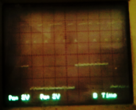
(The picture's not-so-good, it's a screenshot from a video taken in non-ideal lighting conditions...)
Scrolling through the samples, it appears that the upper channel is the clock. I counted ~25 edges the first-go. Did some math, and determined that the sample-rate is *durn near* the clock-rate. So that might account for the fact that some clock-pulses *appear* to be aperiodic... The clock rate is too high for my sampling-rate.
So I bumped up the sampling rate to 20MHz just to check and now I'm counting ~30 edges that appear quite a bit more periodic. (And I'm running an AVR rated for 8MHz at 20MHz, woot!).
side-note: my 'scope is rated at 20MHz... in "digital mode" that's reduced dramatically. In analog-mode I've viewed *repeating* logic-transitions at upwards of 100MHz. So, even though the clock-rate of this data-burst is at my 'scope's rated limit, I should still be able to see the data in analog-mode due to the fast-repeating of this "logic analyzer".
The fast-repeat Fix:
Been digging even deeper into the code... As I said before, this project was collecting dust for nearly a year, so it's taking some time to refresh my memory.
The fix for slow-repeating was much easier than I expected; I completely forgot that I had set-up an SDRAM-Refresh each time the sample is output... two, actually. One before starting, and another after finishing. NEITHER are necessary, as I've experimentally verified that this SDRAM is reliable even when refreshed only once every *10 seconds*. Further, the very act of refreshing the image on the LCD display (as happens periodically, even when repeating just a window) *causes* the SDRAM to be refreshed, as well. (Opening a page and closing it acts as a refresh on that page; displaying on the LCD cycles through all the pages, thus the entire SDRAM gets refreshed).
The Future:
I wasn't planning on doing this any time soon, but it appears I'll have to if I want to read this data-burst correctly:
The original idea with "Free-Running" SDRAM was that once it's free-running, it no longer needs MCU control... So, then, there's no reason it couldn't run at its full-speed (133MHz=133MS/s).
It *will* require some hardware modification, and a bit of thinking...
I've already pondered it quite a bit in the past. Running the SDRAM at, say, 100MHz, and the AVR at, say, 10MHz means that (some of) the commands sent to the SDRAM have to be *one-shot*... Most commands can be repeated back-to-back. E.G. a READ command at a specific address would be written by the AVR to the SDRAM's Command/Address lines for one AVR clock-cycle, then the SDRAM would receive that same READ command 10 times. This is fine, since each consecutive read at the same address would just cause it to repeat the same data. Similar is true for WRITE. (Actually, that's been a nice factor with really early tests, as it meant timing needn't be precise and no latches are necessary). BUT. Some commands *cannot* be repeated like this... I can't recall the exact ones, but "Precharge" "Activate" and "Load Configuration Register" come to mind.
So, for these, I'll have to have a one-shot circuit... at the very-least on the Chip-Select line. I'm imagining a shift-register and a couple gates running at the SDRAM speed.
The original design-plans for this one-shot were for sdramThing1.0 and 2.0, which didn't have a "side-kick." Basically all they did was continuously repeat the entire contents of the SDRAM, as loaded, slowly, by the AVR at boot. (E.G. a non-changing LCD image).
The Side-Kick added the ability to sample/repeat arbitrarily, which makes it great as a logic-analyzer, but the wiring-method had to change, and in-so-doing also required a new scheme for sending commands... It relies heavily on timing. E.G. a "READ" command is issued, then exactly three clock-cycles later (the CAS latency) the data is read... on the same pins that issued the read-command. So, this will get even more complicated with one-shot circuitry. Also, there's quite a bit of precision-timing with the Data-Mask pins which can be used to inhibit writing/reading at certain locations...
Another possibility is to run the SDRAM at the MCU clock-frequency for loading, etc. then switch the SDRAM's clock over to the higher frequency for free-running. It's plausible.
ddrThing:
There've been thoughts about switching over to DDR, as it's becoming increasingly-available in junk-piles, and has a few other benefits to a project like this. But, it's also quite a bit more complex... I mention it, here, in response to the possibility of clock-switching for sdramThing(4.0?)... Clock-switching might not work with DDR, as (I think) there's an internal clock that's synchronized with a steady external clock. So, if I'm thinking toward the future, then I might wipe the clock-switching idea...
At this point, it's moot. I don't have any 100MHz clock sources :)
-
PROGRESS
02/01/2015 at 10:01 • 0 commentsI got samples!
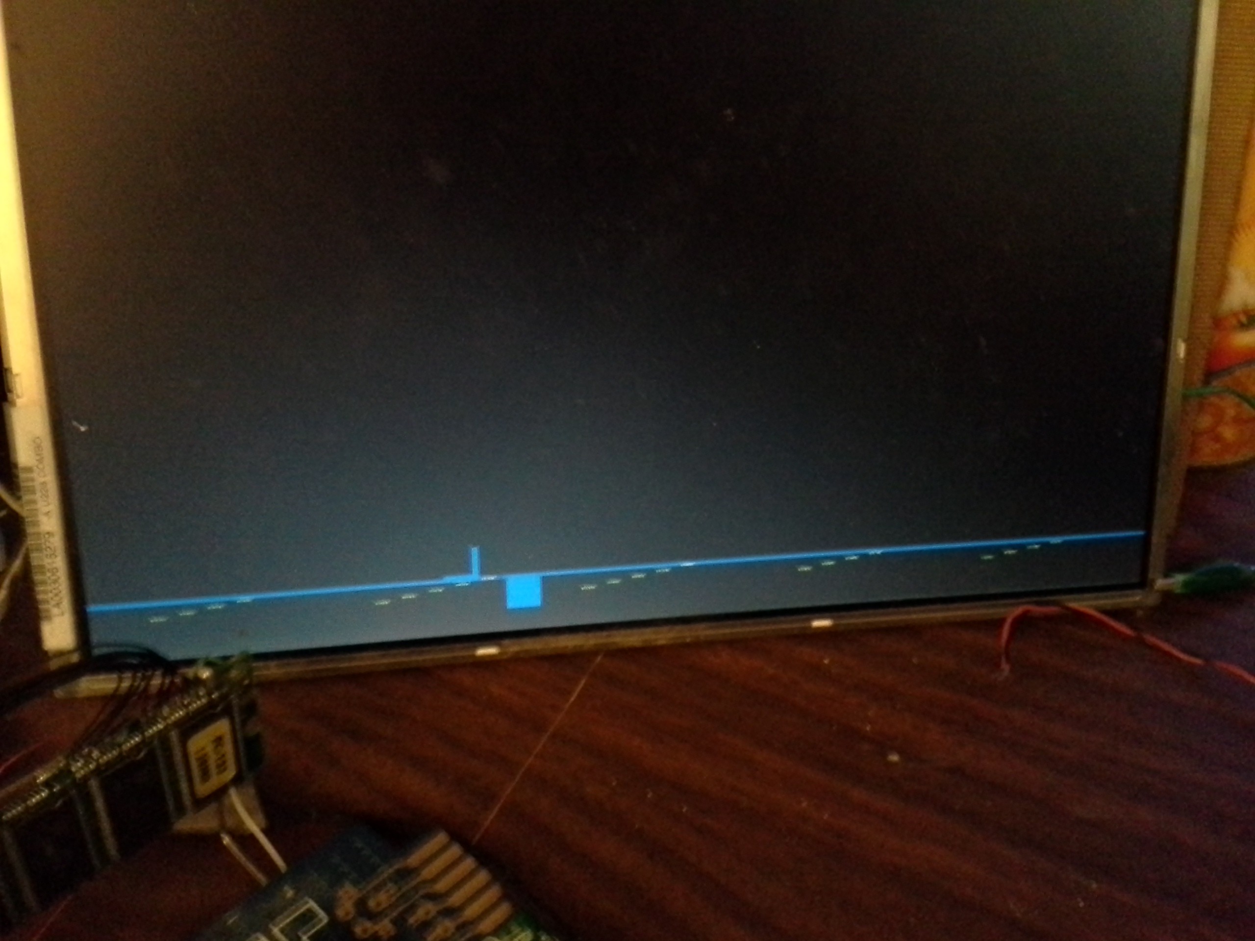
![]()
Definitely some coding to be done... The whole point of the repeating "Repeat" output (to the oscilloscope) is that it repeats the tiny "window" (between the cursors) quickly enough that my old analog 'scope can view it (especially with B-timing), without it being too dim to see.
![]()
Heh, with all those attempts and all those settings this is the best either of my cameras could capture. (and rotated, WTF)... This with all lights off, a custom shade-box (made out of an old beer 6-pack box), and all the night-settings I could find. And it's not even on B-timing... :/
Definitely some software possibilities to improve this... Actually, quite a few, as moving those cursors to that position took about 3 cigarettes and 2 beers on a Saturday Night... (~1hr). But... Proof of concept proven :)
Each pixel on the display represents 7 samples at 16MS/s... the cursors are selecting 27 pixels around a data-packet. There's some math in there. But basically, it appears that the data is clocked at darn-near the sample-rate, so this is a hard-core test of my logic-analyzer. (If the motor-driver works per a similar chip's documentation. there's 18 data-bits transmitted in that packet... I can't quite see it on my 'scope, but *close* for sure... The best I could count was 15... maybe there's an aliasing issue in addition to a blurry-image-issue.)
-
hah!
01/31/2015 at 10:54 • 0 commentsTurns out the data-stream *is* 3.3V (despite being powered by 5V), and with a couple easy re-connects of some of the original and thankfully unmodified hardware there *is* data!
Onward!
Now, the next hurdle is that there's currently no *trigger* input on my logic-analyzer... just a "start sampling" button, which isn't responded-to immediately. So getting the timing right is a crap-shoot.
And the next hurdle after that may be a software bug; it seems to be sampling *twice* (each time?)... so even if the timing's right it'll show the sampled data then wipe it out.
This never appeared before, because everything was lab-testing; my data-sources repeated themselves. This one does not.
Good, anyhow. There *is* data, and I don't even have to do level-shifters. They should be done at some point, but would be better-done with buffers rather than XORs (heh, six buffers per typical 7400-series chip, nice), but software definitely needs improvement, and it feels more productive to work on, for some reason... maybe because I knew these issues were going to have to be attacked soon.
-
slow-downs
01/31/2015 at 09:36 • 0 commentsSpent a large chunk of the day getting rid of the test-clips all over the place... Spent a large chunk of yesterday figuring out where they had to go in the first-place.
So, now there's a screw-terminal block for the 'scope outputs and data inputs, and a header(!) for the "remote" (button interface for the cursors, based on anaButtons).
Currently it only handles the two channels ("Red" and "Green"), but the terminal-block is big enough for 6, and the portion of SDRAM dedicated to Sample/Repeat is 32bits wide (DIMMs are 64bits, the first 'bank' is dedicated to the "free-runner" and the second bank is for the "side-kick" which handles SAR). Obviously, only two channels can be *viewed* at a time (the two colors on the LCD, and two traces on my 'scope), but all 32 are sampled/repeated simultaneously... And there're thoughts along the lines of means to slow-down repeating for e.g. uploading to a computer... There're thoughts about *everything* ;)
Also, spent a bit of yesterday revisiting the code... updating it to use newer versions of commonThings, a little bit of debugging, etc. But mostly just reminding myself how it works, which pins to use, etc. since I never did write a user-manual.
But, now that it's wired-up in a reliable and intuitive way, I've run into a couple other slow-downs...
First, the data-source is 5V-logic, whereas the SDRAM is 3.3V... So, time for a 74AHC-series buffer... my stock is rather low, but not nil... plausibly I'll be using some XORs for the purpose. It's a good idea for the future, anyhow, 'cause the other slow-down may render the current mishmash goals difficult.
The other slow-down is that the printer was dead last I tried to power it up... It blinked for a second, I heard the stepper tick, then it powered-down. Aaannnddd... I got a bit overzealous(?) in tearing it apart for the X-axis experiments (with the encoder), making it even less-likely to get as far as ticking that stepper-motor. Yeah, I all but destroyed the possibility of wiring it all back together; The ribbon-cable's been soldered and epoxied, the inkjets themselves have been stripped from the carriage (and basically *ripped* off the ribbon-cable, 'cause it was darn-near impossible to access), the opto-sensor that detects the edge of the paper has been removed (and was on the unusable ribbon-cable anyhow)...
So, as it stands, I get nada. Switching on the power-supply causes the power to go active for a second, but no data's sent to the driver-chip... none of the very data that I was planning to spy-on with my logic analyzer.
All hope is not lost, but steam may be winding down.
Oh, and my hands are still covered in ink from yesterday's cleaning ;)
Oh, and... I wrote a nice project-details yesterday, summarizing the idea behind free-running SDRAM... and then outta-the-blue literally seconds before submission, my kernel halted.
sdramThing4.5 "Logic Analyzer"
An AVR, 128MB SDRAM DIMM, old laptop LCD, and a handful of TTL chips -- 30+MS/s 32-channel logic-analyzer interface for an analog 'scope