Jeremy
-
Show Time!
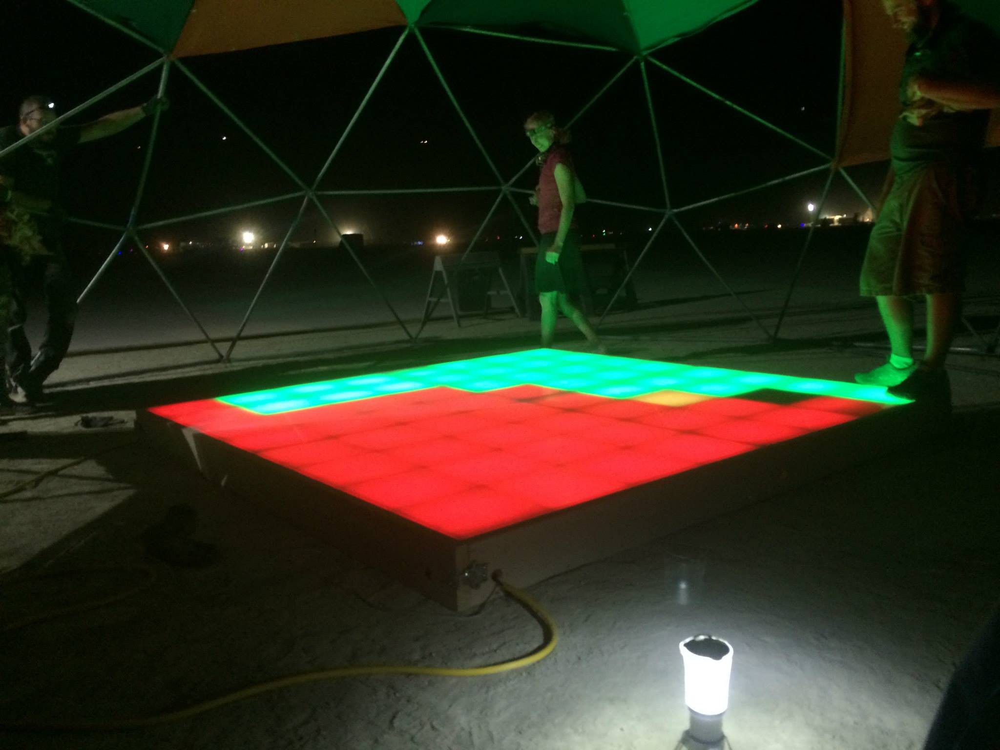
08/20/2016 at 01:08 • 0 commentsTL;DR I'm packing up the floor and heading out to Burning Man with it on Wenesday, August 26th. If you're on the playa, you can see it at 5:15 & D at The Future camp.
Quick Demo:
The Final Production
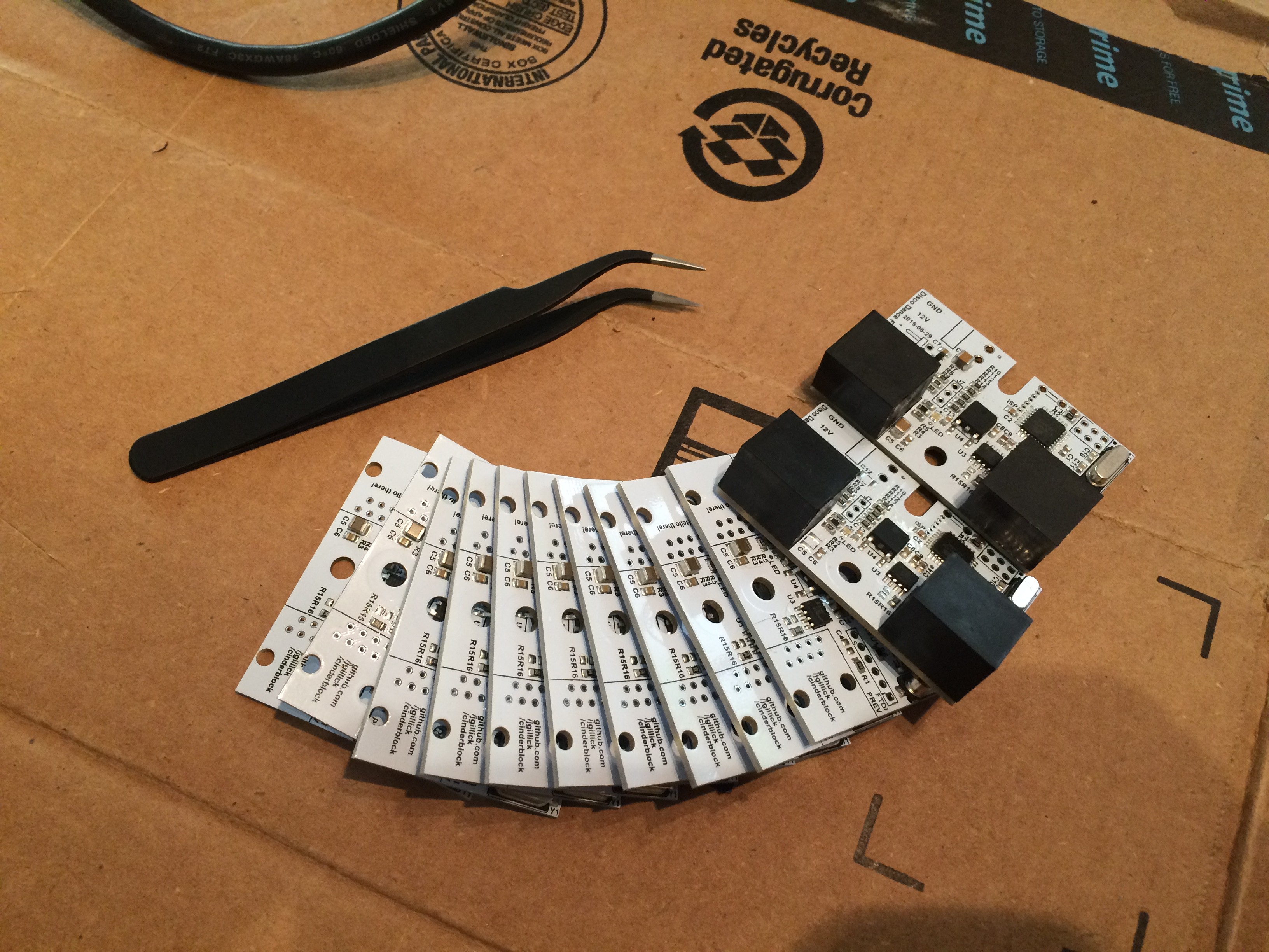
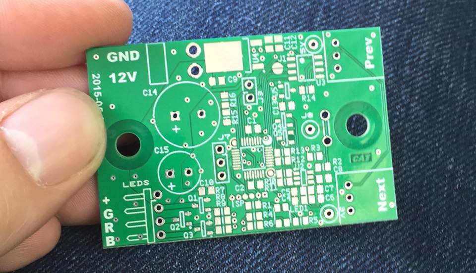
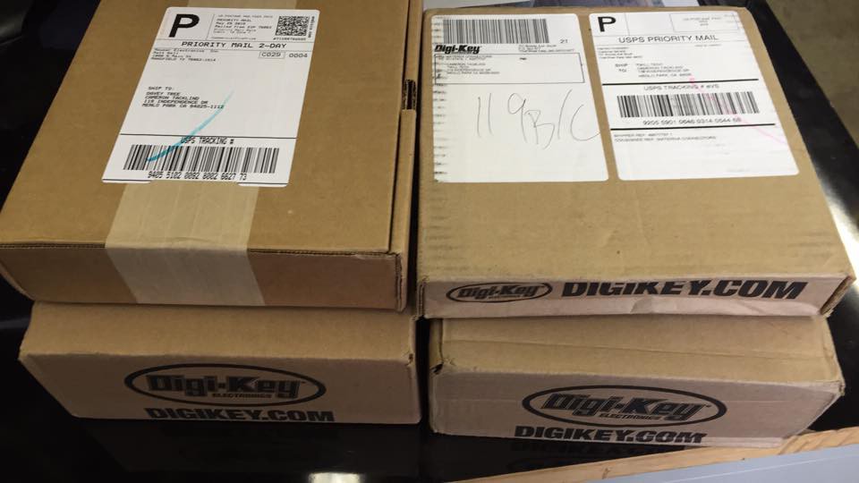
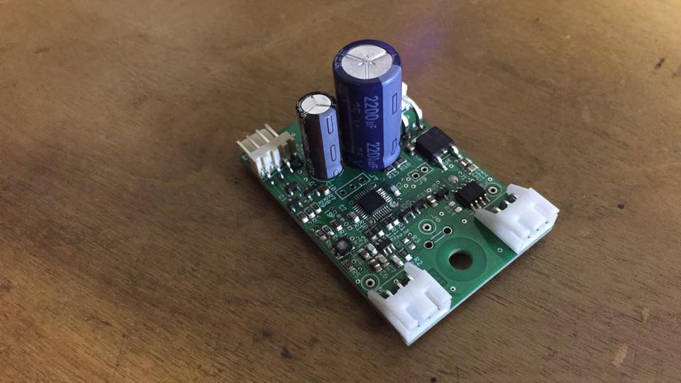
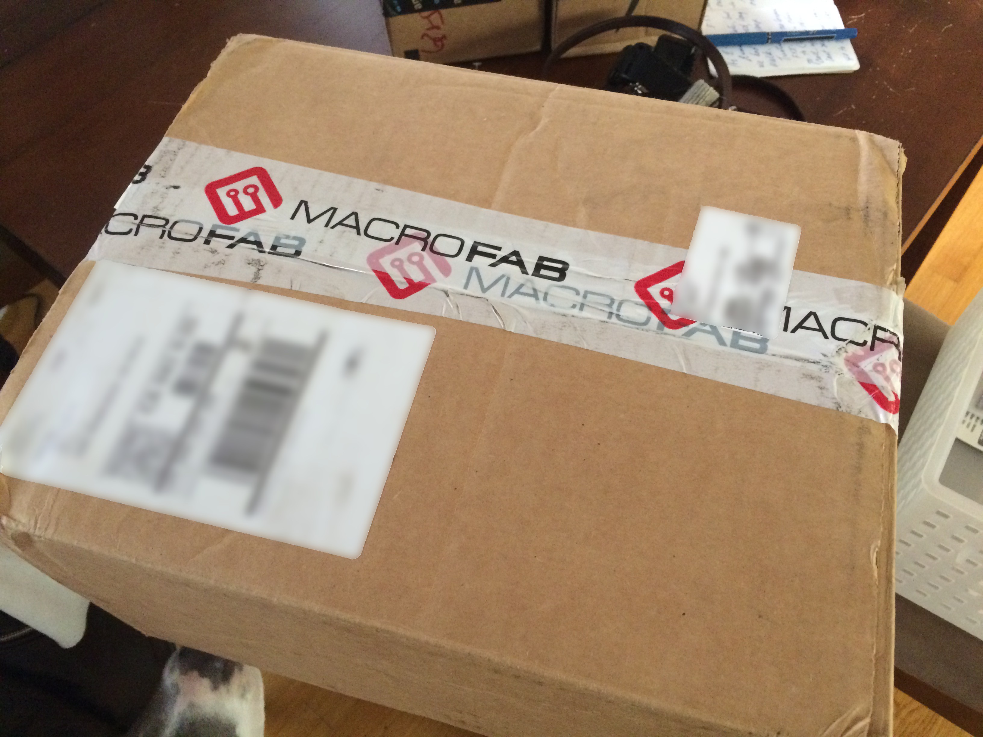
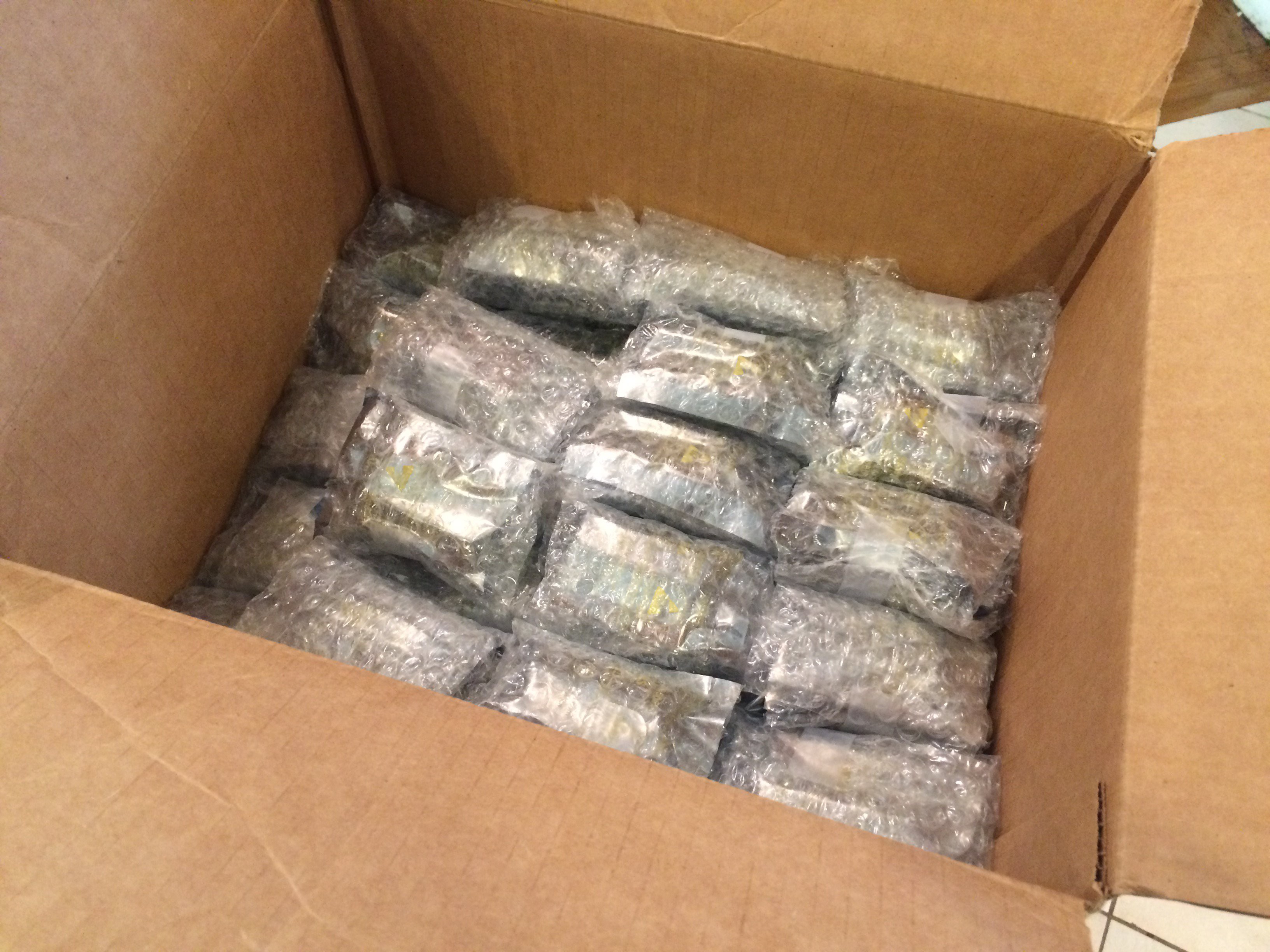
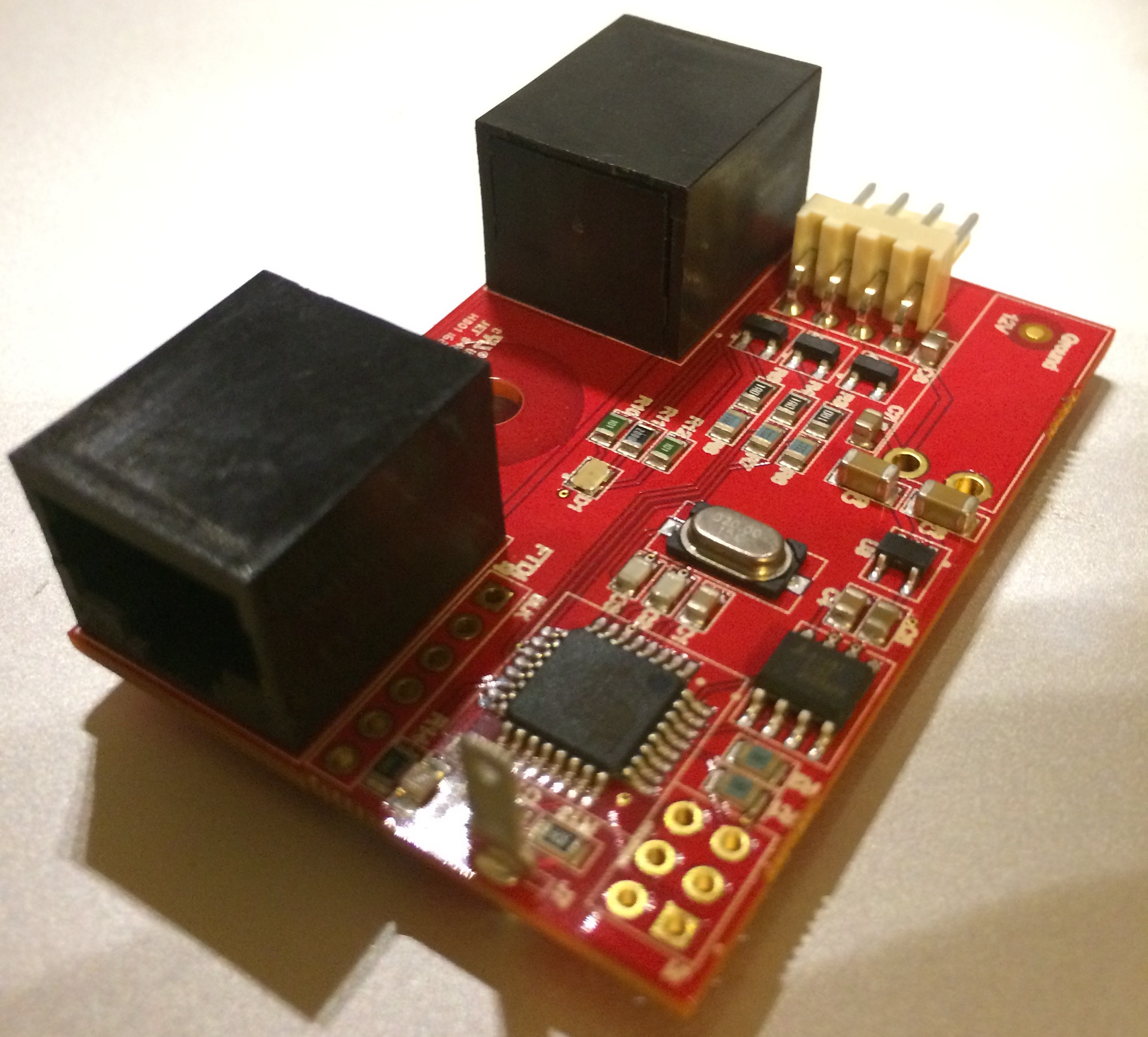
In my last post, I had put in my production order with MacroFab and was waiting for the boards to come in. Last Friday they arrived and it was beautiful!
![]()
![]()
![]()
Although, there was one problem...the blade connector for the touch sensor was missing from each board (the empty hole to the left of the Atmega chip). I emailed MacroFab and they bent over backwards to make up for the missing part. The good news is that, once I was in a rhythm, the part only took about 30 seconds to add to each board.
(Even though there was a mistake, I was really impressed with their customer service and how hard they worked to keep me happy. So I'm still a big fan of Macro Fab.)
A weekend of soldering and assembling and I had a full working dance floor! So far, the touch sensors are working pretty well. A few squares are a little too sensitive, but that can be tweaked in the software.
This was the goal I had 2 years ago, and it's finally coming together!
See you soon!
If you're out at burning man, come find me at The Future (5:15 & D).
-
Production Order!
07/18/2016 at 08:11 • 0 commentsLast week was a pretty big week -- I put in the full production order of 100 circuit boards to MacroFab!!!
Test Boards
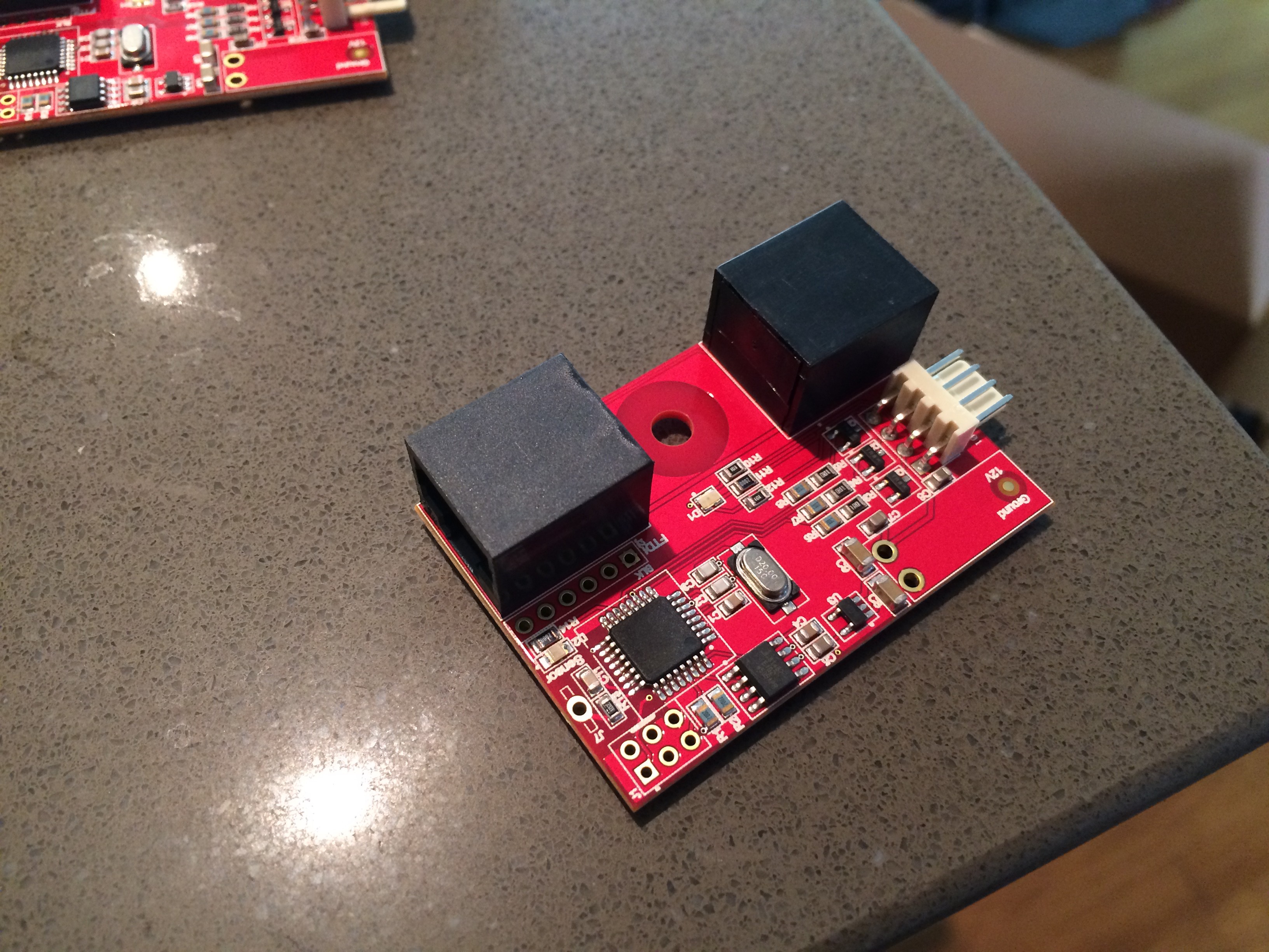
This year I'm using MacroFab to do the manufacturing of the boards. This is a new PCB manufacturing and assembly company and I was a little apprehensive; so about 3 weeks ago I ordered a single test board. It was delivered right on time and was simply perfect.
![]()
Isn't it pretty!
After running it through a series of tests, all functions appeared to be working. Time to put in the production order...almost.
Sensitivity Training
I had been building a series of boards by hand and by the time the test board came in, it was time for more full-scale testing. The great news is the touch sensors still seem to be working well! The less great news is that sometimes they are a bit over sensitive.
After tweaking a bunch of variables, it seemed that reducing the sampling capacitor from 22nF to 10nF makes tuning the sensitivity much easier.
Production Order
Ideally, at this point, I would have time to test the boards with the new capacitors and make sure this is a solid option. Unfortunately, with Burning Man about a month and a half way, I need to get the order in. So I checked everything I could and at about 3am held my breath, closed my eyes, pressed the order button and went to bed.
So in about 3 weeks I should have about 100 boards at my door step. If everything goes well, we'll have a full-size working dance floor and an awesome party in the desert.
Until then, more manually assembled boards and testing.
Wish me luck!
-
How the touch sensors work
07/01/2016 at 01:09 • 0 commentsThe main thing that makes the dance floor interactive is the touch sensors under the surface. This post is going to dive into how this works.
What are my options?
While working on this project I had a variety of suggestions from friends for what kind of sensors to use. Here are a few of them.
Pressure Sensors
By far the most common suggestion. I spent a considerable amount of time building homemade foam and velostat sensors and testing their effectiveness. The plastic doesn't have tons of flex, so pressure from one little square will be transferred to neighboring squares. It would be possible to filter this out, but in small tests, it was proving difficult when you have many people on the floor at once.
IR Sensors
Similar to some touch surfaces, you can send IR light through the surface plastic and detect how much gets scattered when the surface is touched (i.e. frustrated total internal reflection). For a continuous piece of plastic, it become challenging to detect for just one square, especially when we're pumping colored light out of it. Not impossible, just outside of my range of experience.
Tap/Accelerometer Sensors
This is a common technique made popular by SparkFun. The idea is that each square has an accellerometer and can detect taps (or stomps).
Off the bat, accellerometers are not cheap and I need 80+ sensors. Also, people would have to actively stomp on the floor to be detected. Light steps or foot sweeping motions would not be registered. Lastly, it can detect the step, but not the continued presence of the person.
Capacitive Sensors
Capacitive sensors can be tuned to pick up people in proximity to the sensor without actually touching it. This lets the dance floor accurately detect when people are lightly whisking across the floor. It's also cheap. Just put metal chicken wire against the plastic and attach a wire from that to the MCU.
Writing a Capacitance Library (or not)
If you've been following along with past logs, you'll know about the struggles I've had getting the capacitor sensors working.
Last year, I was taking the Arduino approach. I had never programmed pure gcc AVR C/C+, and was trying to build my own library based on existing work. Boy was this year a BIG learning experience.
The original library was a basic charge/discharge circuit. The problem was that, at the sensitivity I was going for, there was way too much noise to filter out. Every time I thought I had it working, it would break at full-scale. This included was many sleepless nights trying different things and not getting much closer. And into the wee hours of the morning I went.
Then my friend suggested I try the QTouch library, by Atmel. This wont work in a stock Arduino environment, so went back to square one to teach myself straight AVR GCC programming. Surprisingly, when I got everything compiled (which took some trial, error, and a lot of learning) the sensor right out of the box! Over the last several months I've seen very few false positives, even at full-scale. If only I had started with this: *facepalm* (I'm reasonably sure my friend suggested QTouch early on in the project, but going from Arduino to gcc AVR libc was too much to take on at the moment)
If you want to try a simplified QTouch example, I've uploaded a basic demo to github: https://github.com/jgillick/AVR-Libs/tree/master/QTouch
The Anatomy of a Dance Floor Touch Sensor
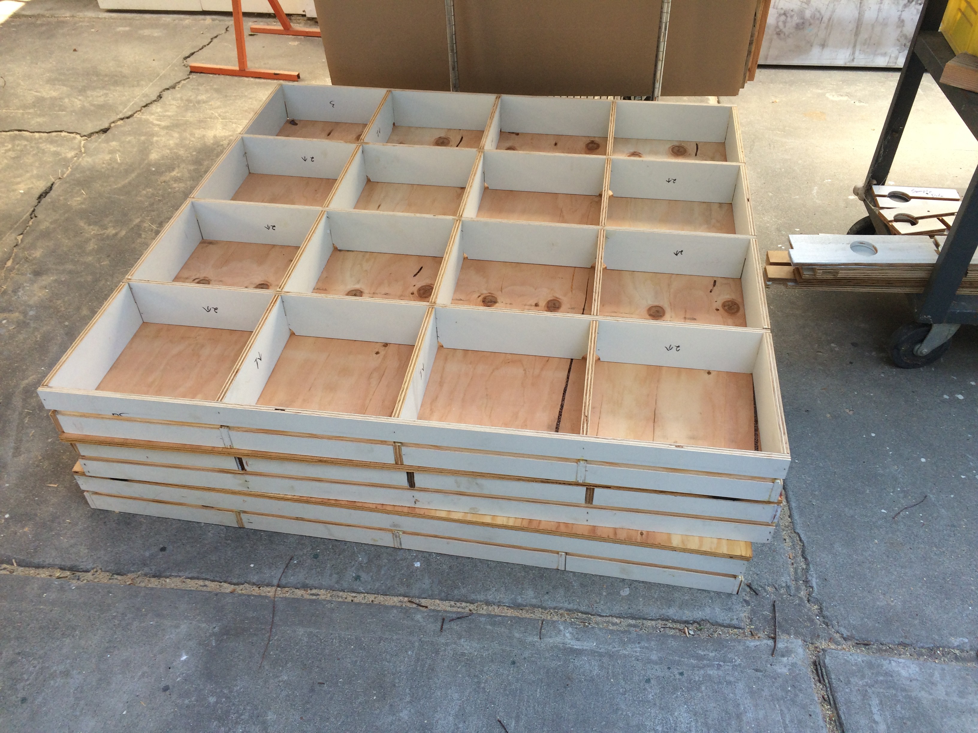
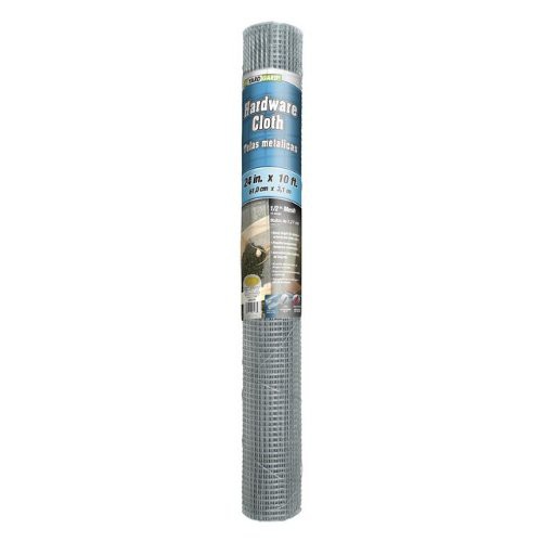
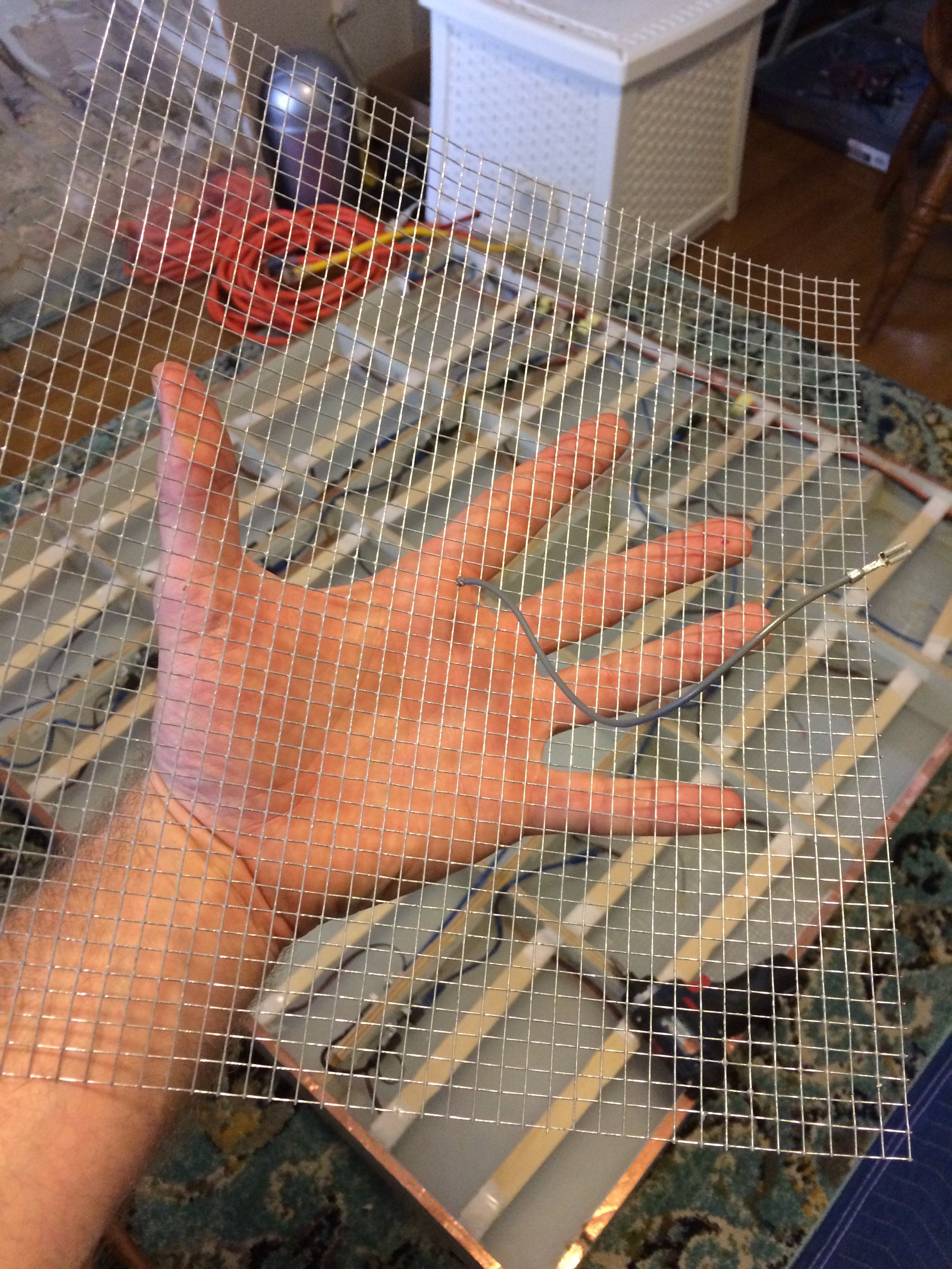
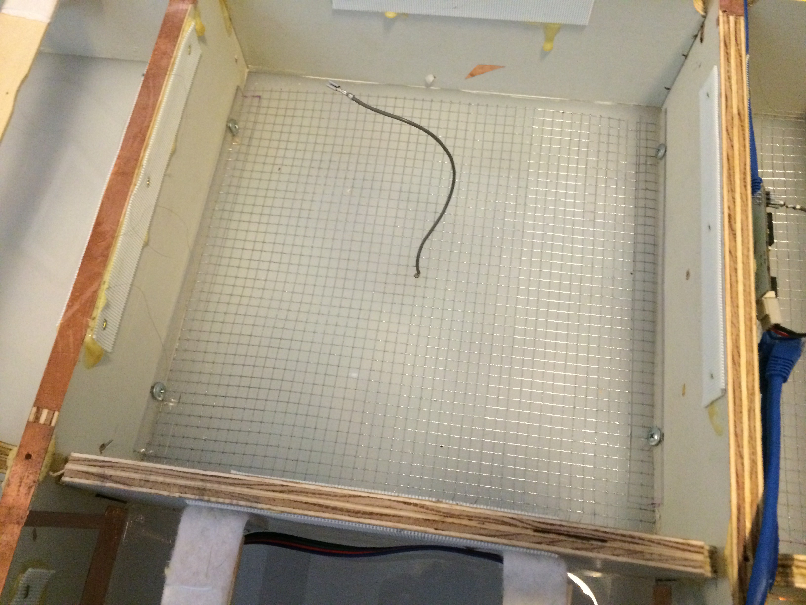
It all starts with the sensor plate. In this case it's just a square cut from of a roll wire mesh.
![]()
![]()
The mesh was cut into a square, just bit enough to fit in the square box. Then a wire is soldered to the center.
![1/2" corner plastic]()
![]()
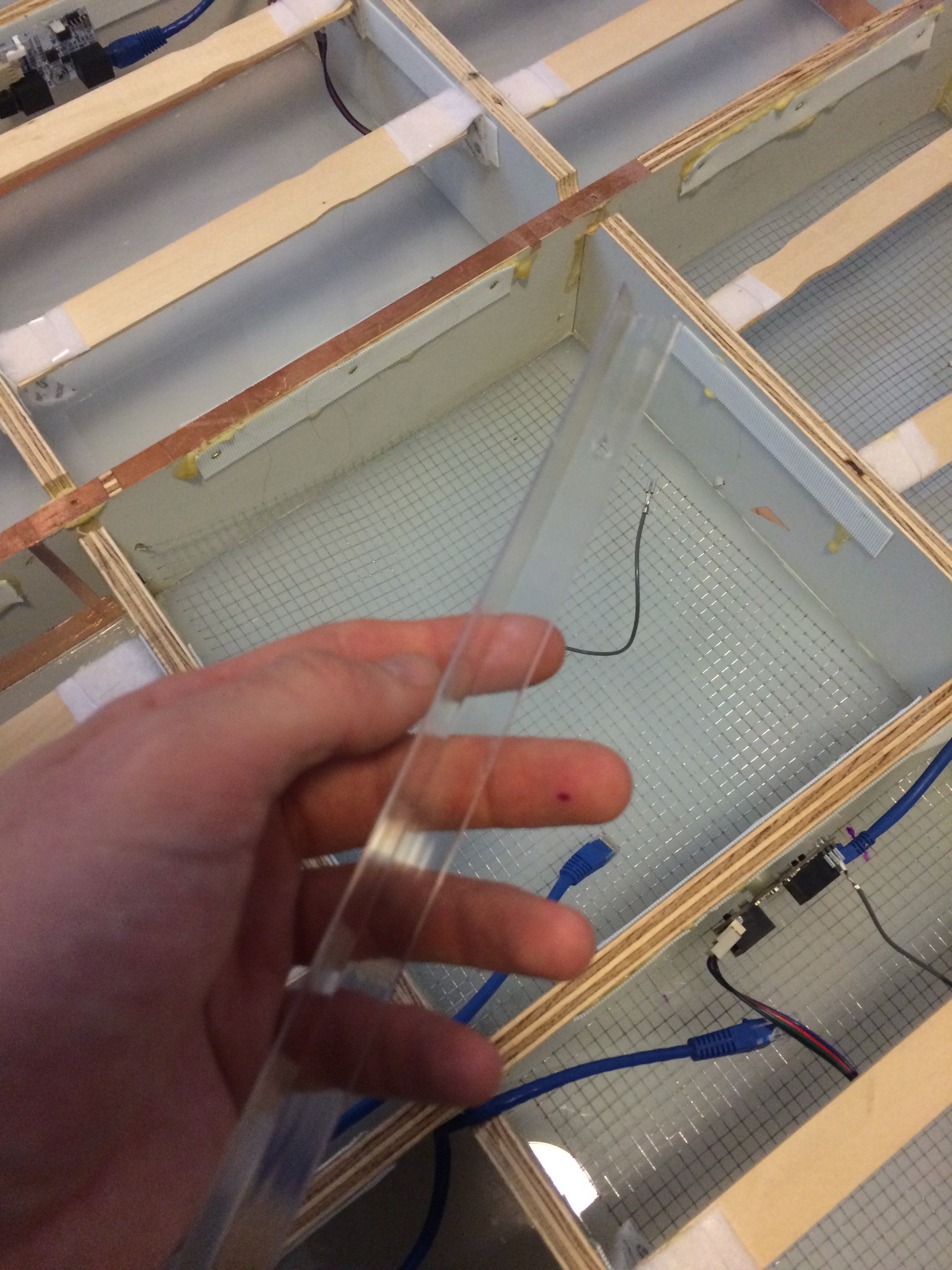
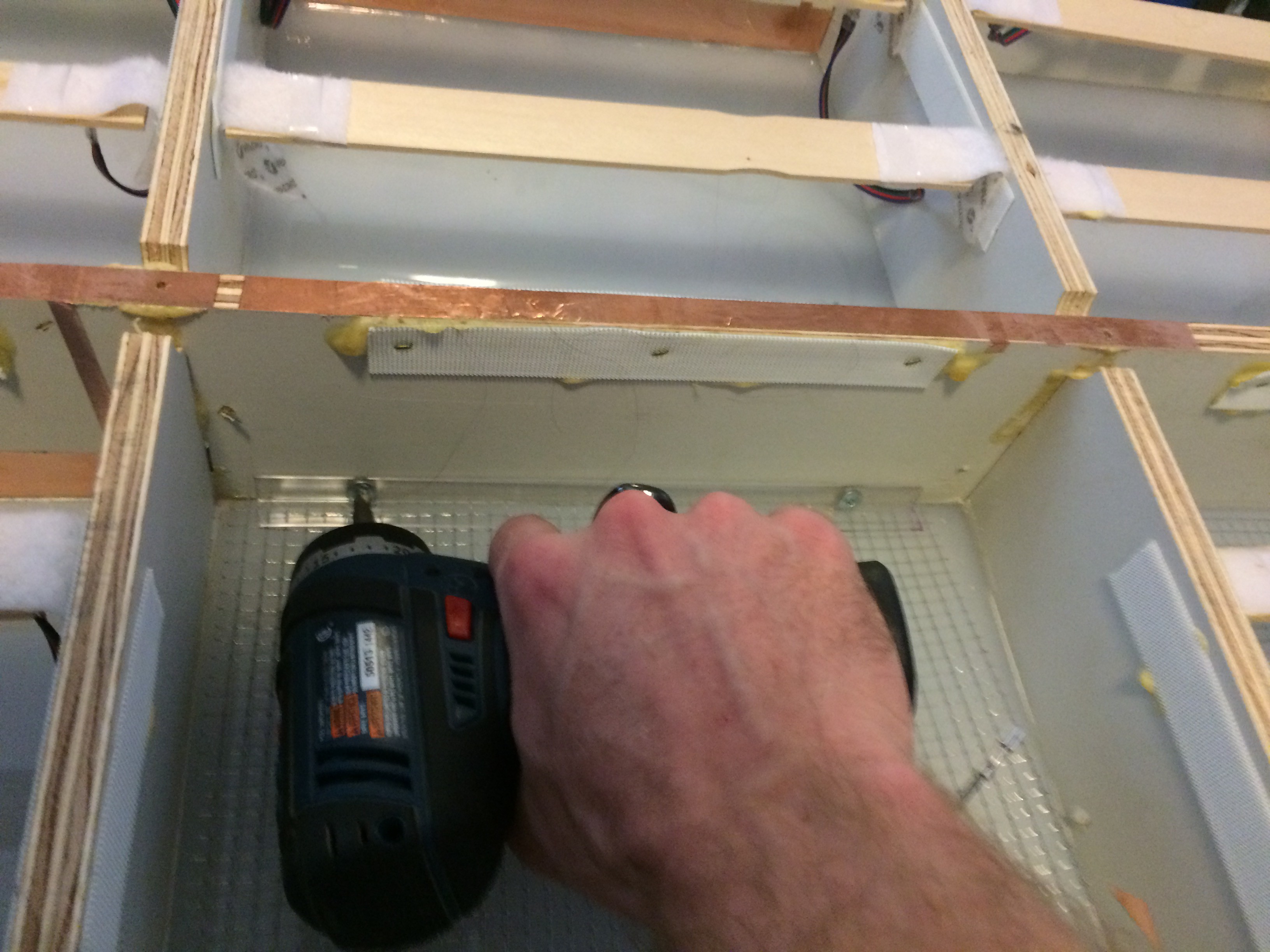
Then it's secured in the box and up against the bottom of the acrylic floor surface with a couple lengths of 1/2" corner plastic. This is the stuff that usually protects wall corners from impact.![]()
![]()
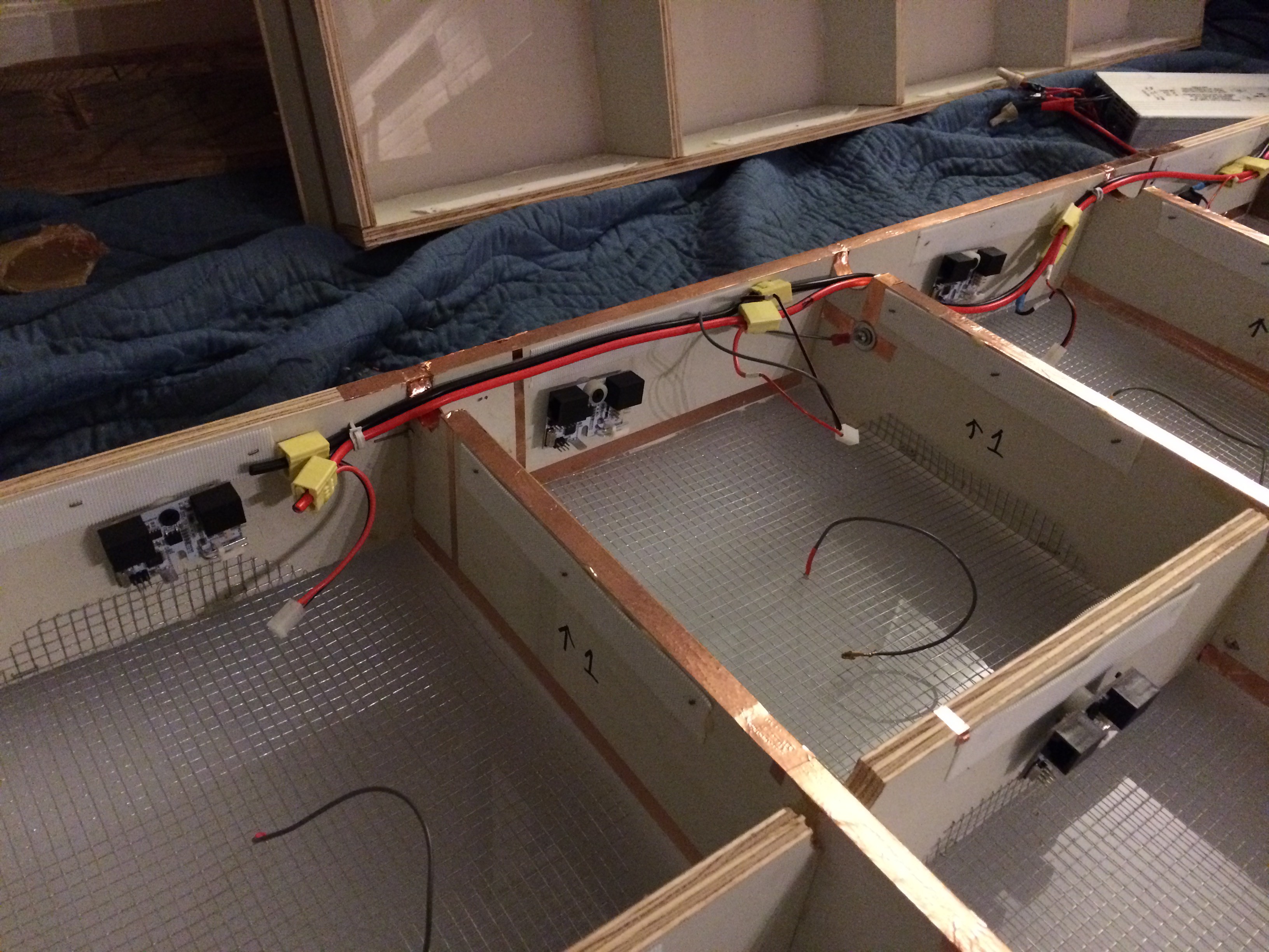
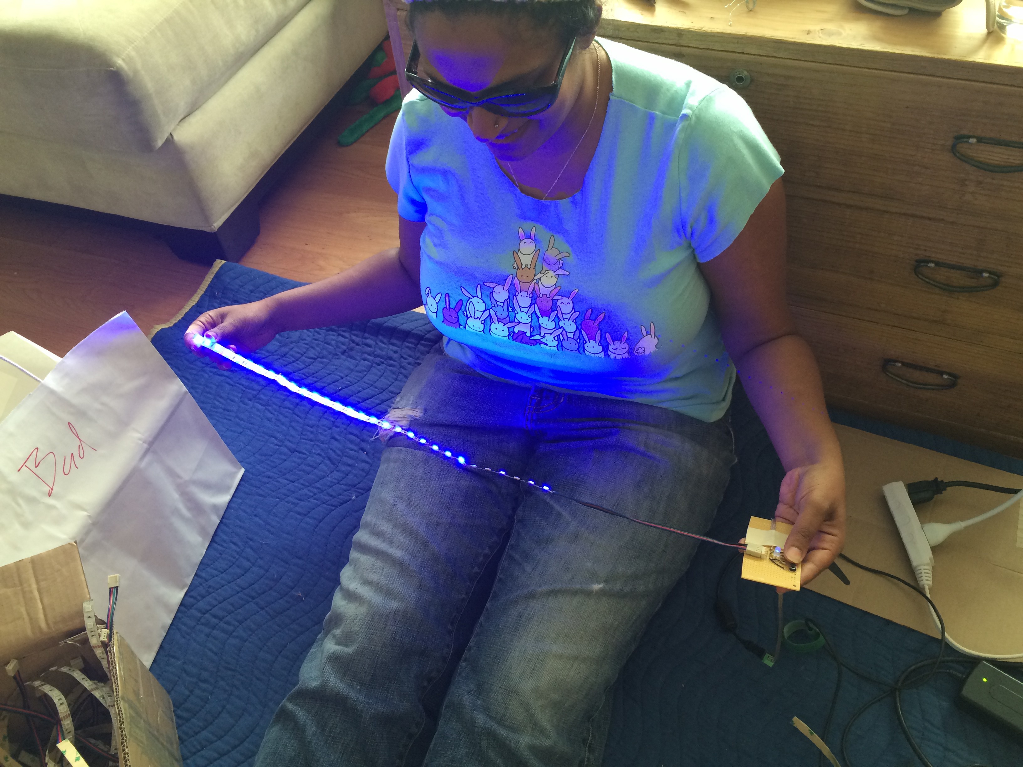
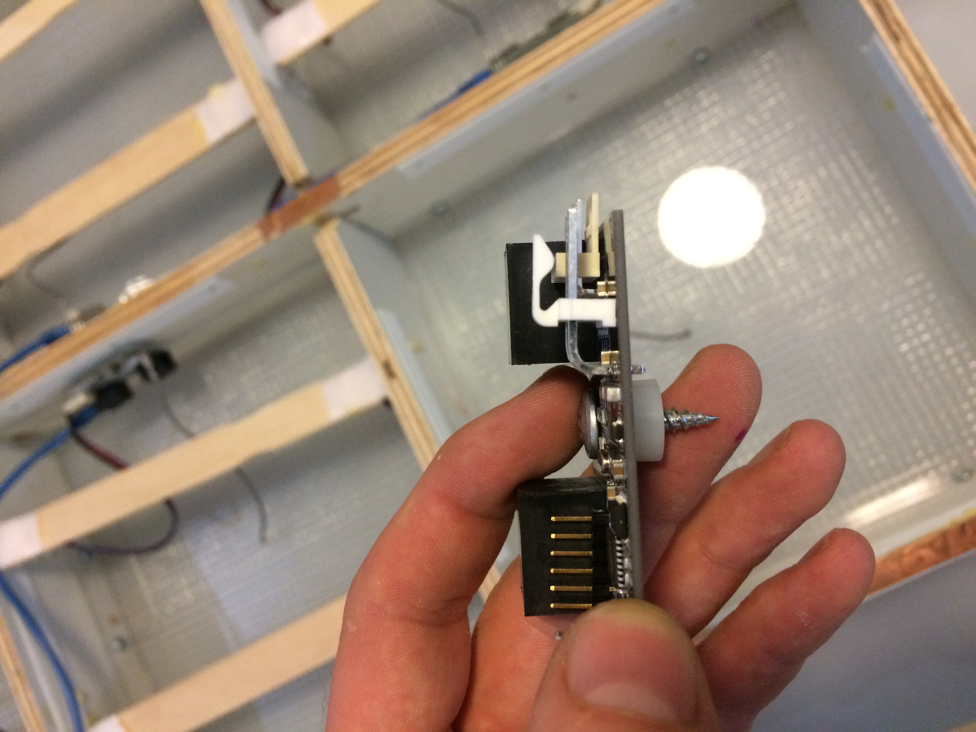
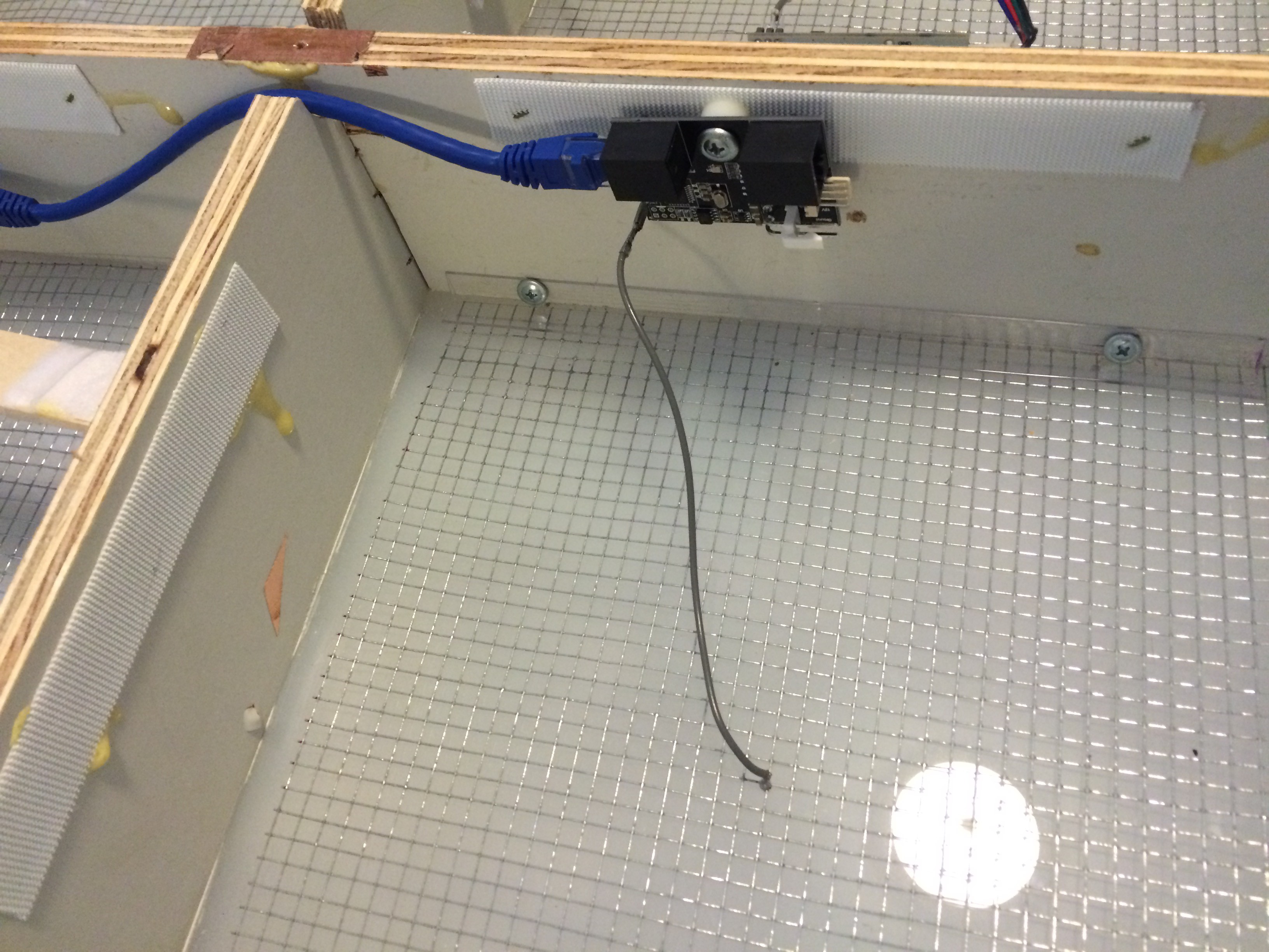
![]() Now we screw the circuit board to the side of the box and plug the sensor wire into it.
Now we screw the circuit board to the side of the box and plug the sensor wire into it.
Power it up and it just works!
![]()
It might be hard to tell, but I'm wearing thick motorcycle boots and sliding my feet between squares to test it's sensitivity.
-
Production Ready?
06/17/2016 at 18:25 • 0 commentsThe past couple months has been a process of:
- Test
- Find problems.
- Send out an order for new PCBs
- Test again
- Find another program
- Bang head against problem
- Rinse and repeat
So pretty much, standard operating procedure. But, as of last night, things are looking up!
View post on imgur.com![]()
Touch Sensors
I assembled 5 of the latest PCBs and threw them in one of the floor sections to test the new touch sensors. There were two big concerns that plagued me last year: too many false positives, and the neighboring sensors creating interference for each other.
When I turned them on, It was like magic, they just worked! (which was thoroughly confusing) So far I'm not seeing any interference between squares and almost no false positives. Then I put on my thick motorcycle boots, and the sensors still picked them up accurately!
Next step is to assemble more squares and test. I'll have another update soon to explain how the touch sensors work in detail.
Communication Protocol
This has been giving me the most grief. I've been rewriting the communication protocol from scratch (github) and everything was working well on the breadboard. The first PCBs I received had the daisy chain lines wired all wrong and then I was having issues with timing and junk data on the serial lines.
To make a long story short, a lot of the junk and random problems were related to floating pins lacking pull-up resisters. A bit of code refactoring and turning on internal pull-ups seemed to resolve the problems and at about 12:30a last night I had several nodes talking together without any errors!
So now the question is...are we production ready?
Full Production?
Last year we used Golden Phoenix in China to produce the ~100 boards we needed for the dance floor. Recently I heard about MacroFab and am giving them a try.
They're a PCB manufacturing and assembly house located in Houston Texas and claim to be able to assemble 100 of my boards in about 17 days for close to the same price as Golden Phoenix. Their user interface for verifying the PCB, BOM and part placement is really beautiful and easy to use.
So I've ordered a single board from them to test the service. If it all goes well, I'll put in an order for the rest of the boards.
To answer the question, I'm nervous to say we're 100% production ready. More testing is going to be required, but I think we're very close.
-
The Results
04/22/2016 at 19:58 • 0 commentsWow, it's been awhile since I've posted an update. So, you're probably wondering, how'd it go?
![]()
Burning Man Dance Floor Retrospective
The month leading up to burning man was a mad dash to finish the floor (and, you know, keep a day job). I didn't get much sleep during that time. It was build - test - build - test - eat. I kept running into issues with the capacitive sensors not providing readings that were stable enough at full-scale.
Everything would start off just fine, but then the sensors would randomly detect things when nothing was there and sometimes the sensors would trigger their neighbors. No amount of filtering would fix it. So, in the interest of getting something working, I dropped that feature from the list and, instead, added a microphone to the system so the floor could react to the music playing. Then we packed it all up and threw it on the truck for burning man.
The day finally arrived. We were on the Playa and setting up the floor. I was really nervous; I've seen many people waste most of their time out there trying to get their projects to work. I carefully plugged everything in, flipped the switch on the controller computer, and waited.
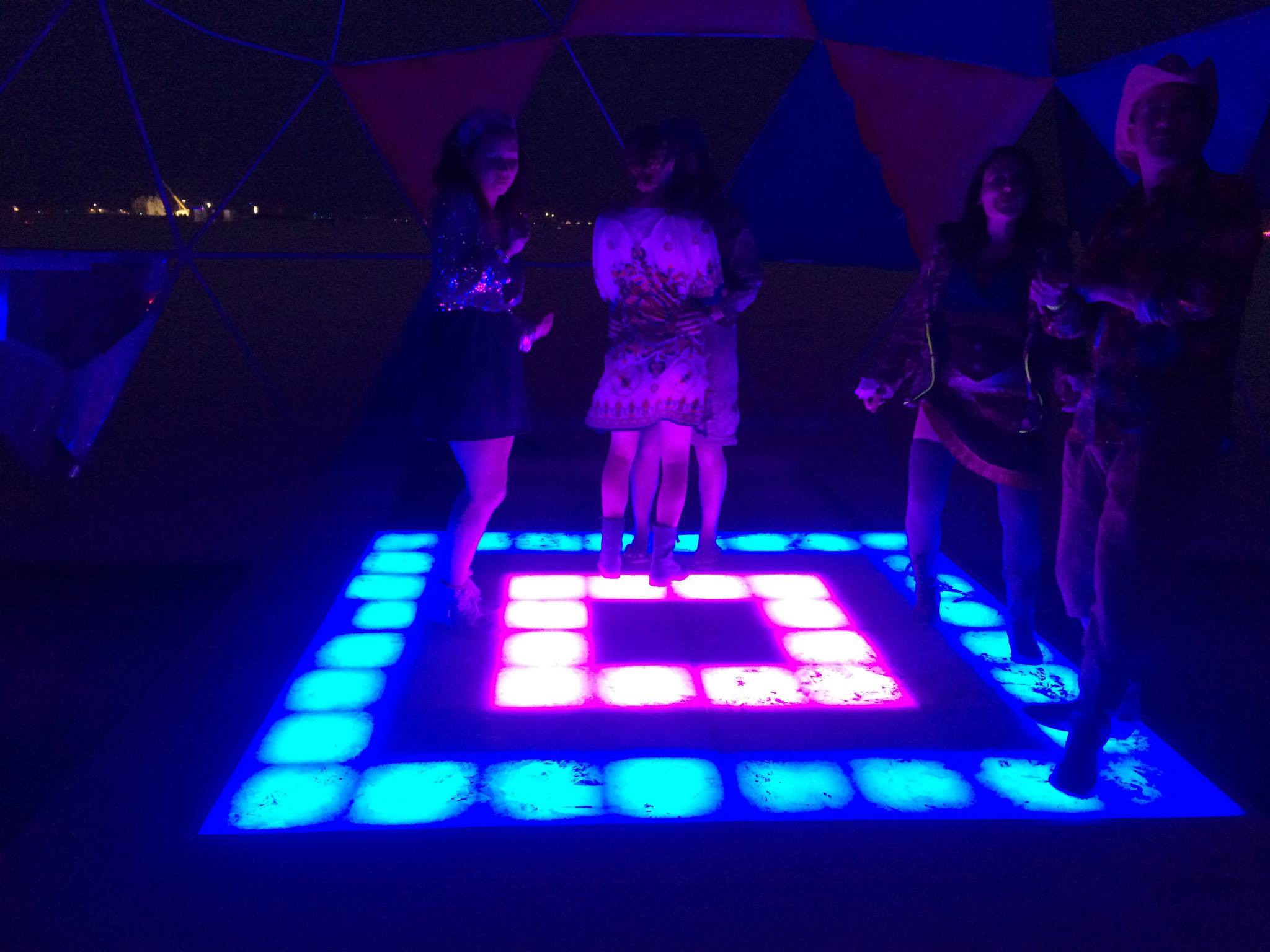
After a couple minutes, the computer finished booting and the floor flickered to life! It was an amazing relief and I let out a happy sigh! Throughout the week, whenever the floor came on, people would come, look at it and dance. No touch sensors, but it was still a huge success...but that's not the end of the story...
![]()
![]()
![]()
pictures from setting up and testing the floor
What's next? Burning Man 2016!
Well, I haven't given up on the capacitive sensors. As soon as I got back from Burning Man I started rewriting everything. I overhauled the communication protocol, played with the circuit design and started playing with different capacitive sensor methods. So far I've found that the QTouch library, provided by Atmel, works really well out of the box. I originally shied away from it because I was working in pure Arduinoland and hadn't worked with straight AVR C/C++. But now I've gotten over that hurdle and will be testing it on the full scale floors in the coming weeks.
I just received the new circuit boards in the mail yesterday and I can't wait to try it out.
Other Planned Changes
Along with getting the sensors working, there are a few other changes I'd like to address:
- Weight: The current floor sections are pretty heavy. I think I can cut this down considerably by taking at least an inch off the floor height and using a lighter base board.
- Outer Frame: The frame that holds the floor together works incredibly well, but is limited to an 8' x 8' square. I'd like to figure out a more modular way to hold the sections together and keep them level.
- Mounting the Acrylic: Currently the plastic surface is attached to the base grid with an industrial strength glue (stuff that's used to stick glass to the side of buildings). This worked well and provided a seamless surface, but it's starting to separate in some places. I think we might have to start using bolts to hold the plastic to the base.
- New Controller: Rebuild the controller softward using Electron and optimize it for a touch screen interface.
Market Street Prototyping Festival
I also submitted the project to the Market Street Prototyping Festival. They'll announce the project selection mid May (crossing my fingers!).
-
Down to the wire
08/06/2015 at 00:07 • 0 commentsA lot has happened in the last month. I've been working nonstop on getting everything finished up and ready for the desert -- which is in a few short weeks (!!!) -- and of course we're running into some last minute problems.
![]()
New Boards
There were a few problems with the last round of PCBs, so we updated the design and ordered a new batch. One of the biggest improvement is the two data connectors. Originally we were using connectors that we'd have to manually crimp ends for (240 wires to crimp, to be exact!). We swapped those out with ethernet plugs so we can use ready-made cords. Also, since we only need 3 wires for the data bus, we can use the other 5 wires for power!
I also ordered solder stencils with this round of PCBs and had an assembly line of board building at the last build party.
![]()
Capacitive Sensor Hell
The topic has been my personal hell for the past few months. I was able to get the capacitive library working well on its own, and of course, it all blew up as soon as I threw it in the matrix of floor nodes. Now it's returning numbers that are completely unstable and useless.
I have a few theories:- Interference from neighboring floor node sensors.
- Communicating on the bus at a constant 250kbps is not giving the capacitance library enough time for sensing and processing.
- The new power supply might not be grounded well enough.
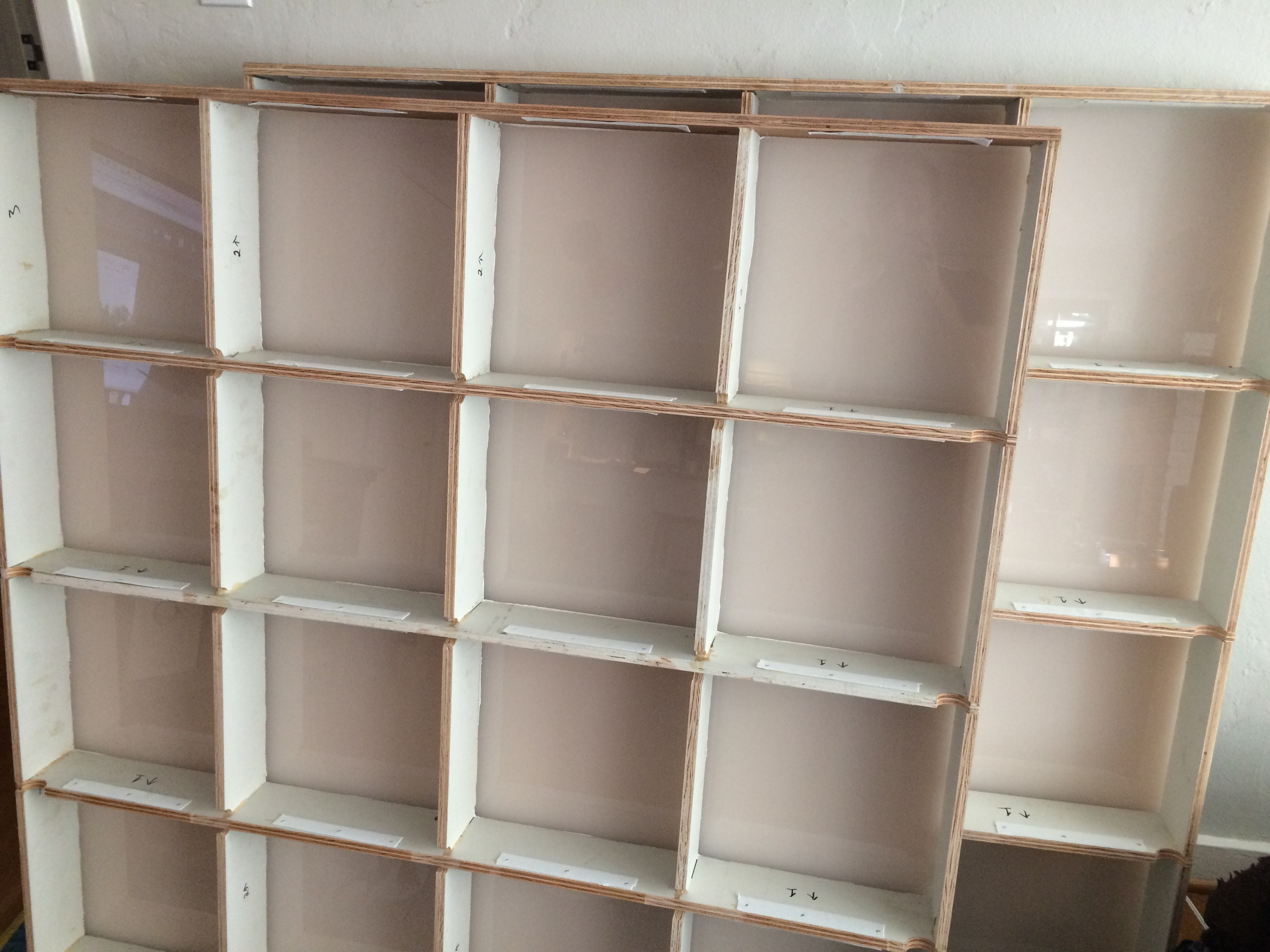
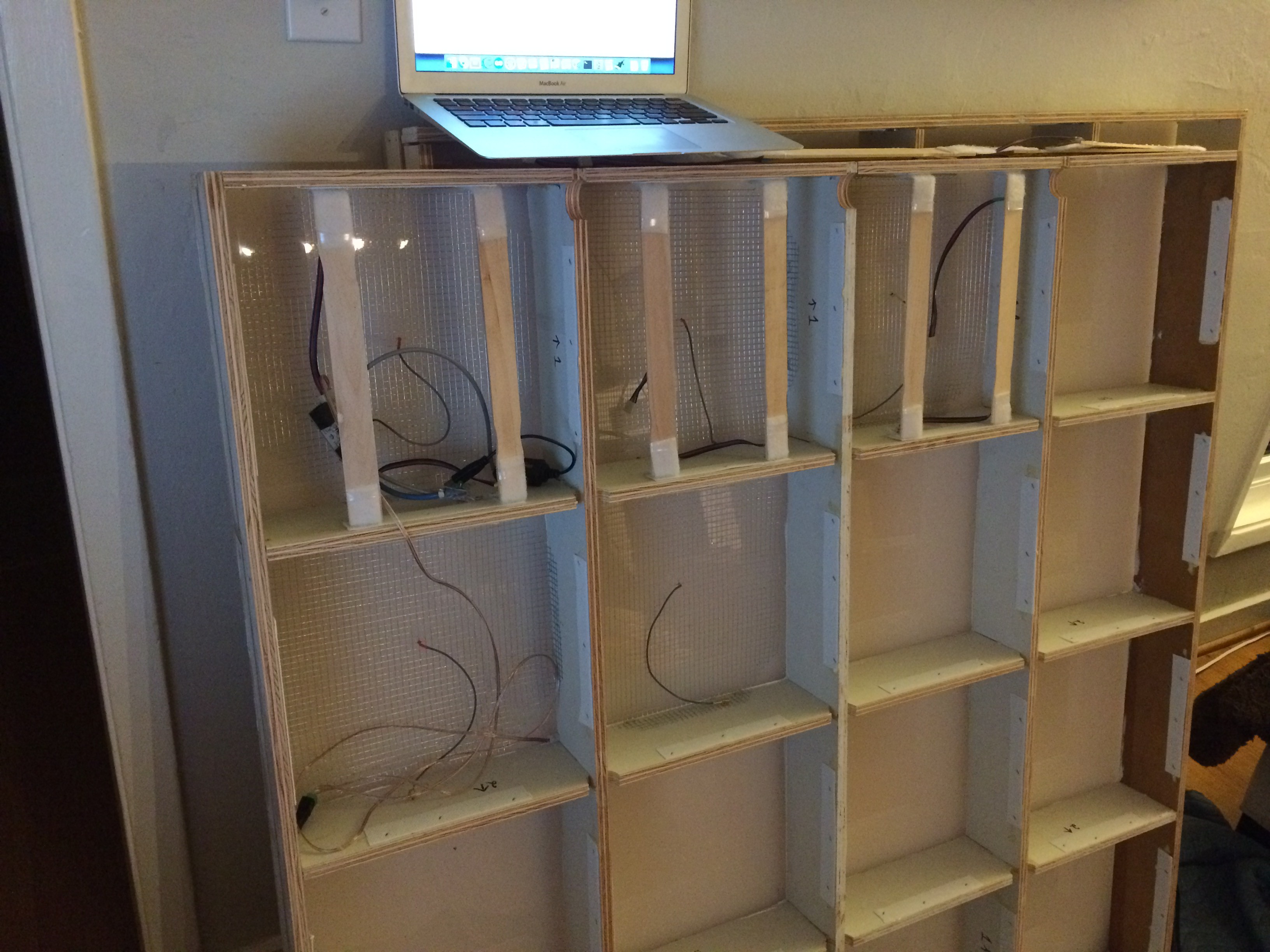
Floor Sections
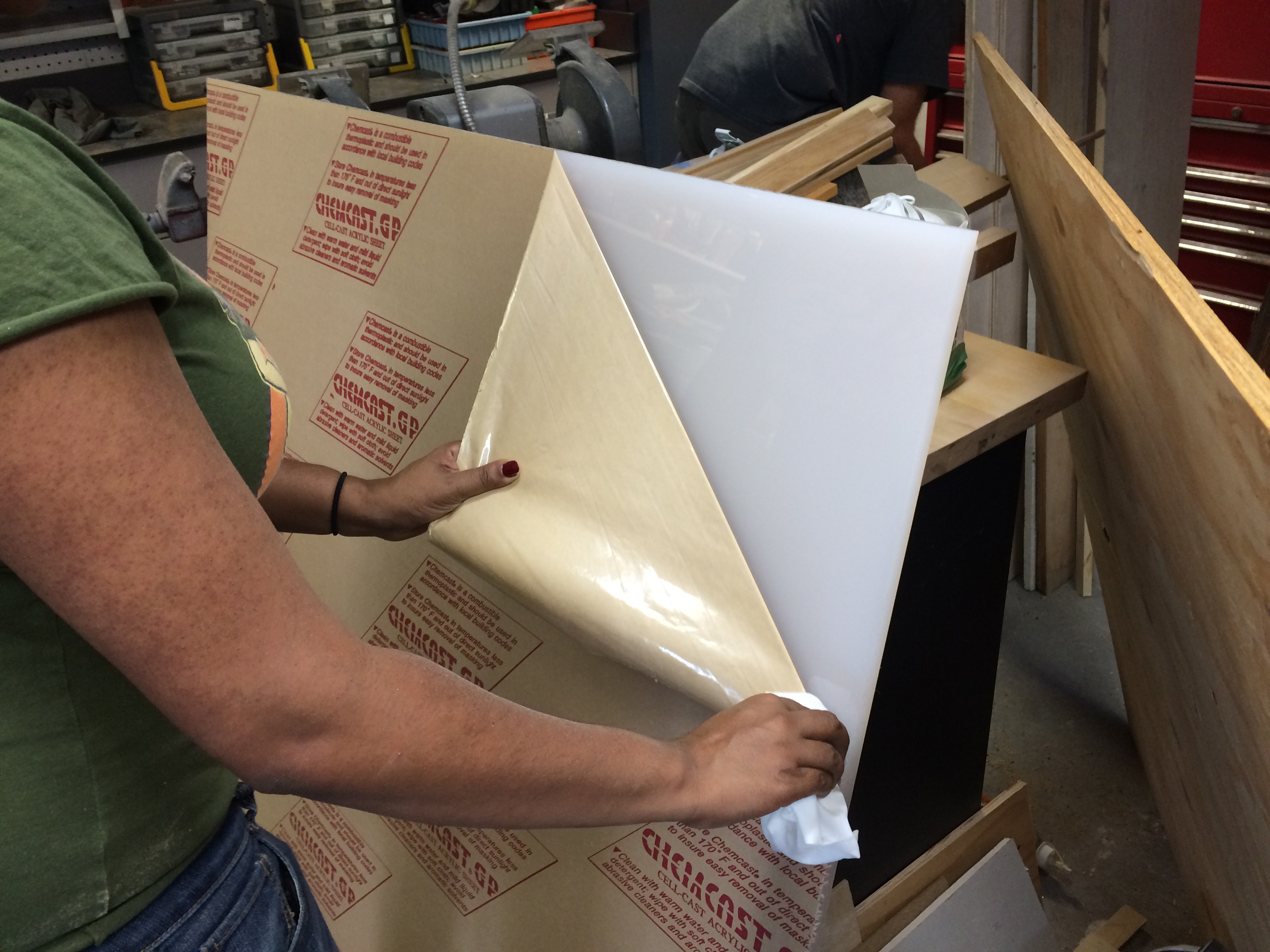
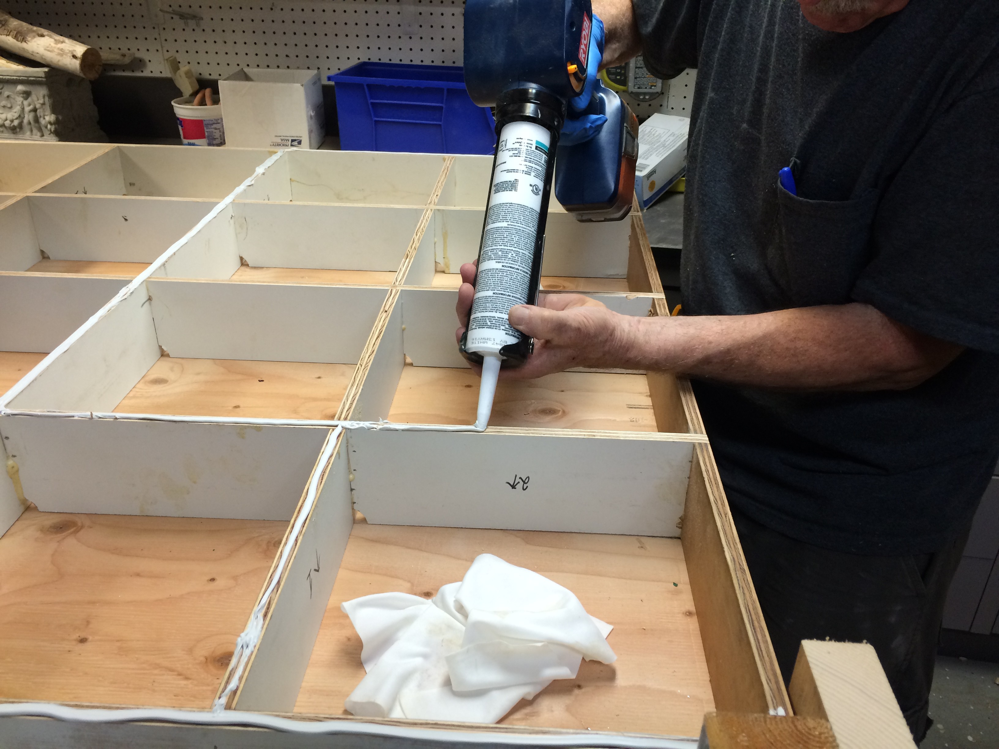
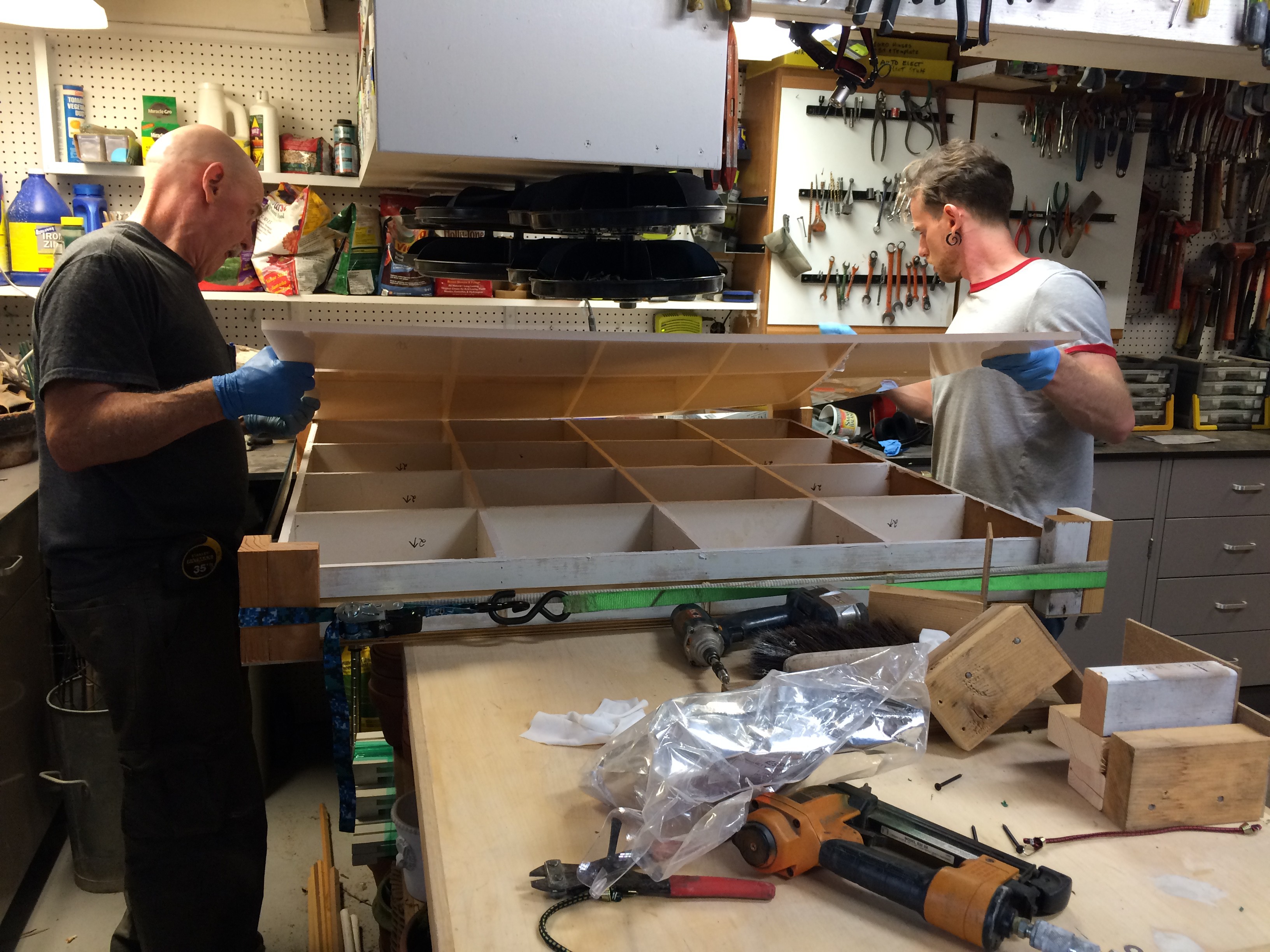
We finally picked up the plastic and some high strength silicone glue and started putting it all together. It feels great to finally have a full floor section to load electronics into.
![]()
![]()
![]()
New Bus Protocol
I won't get too much into the details now, but after quite a bit of discussion & debug, we decided to rewrite the bus protocol to make it more efficient. Now we can get the status of all nodes with a single byte per node (previously it took 5+ bytes). More details to come.Assembly
Next is to do the final assembly and throw a dance party before Burning Man!
![]()
![]()
-
Build Party Weekend!
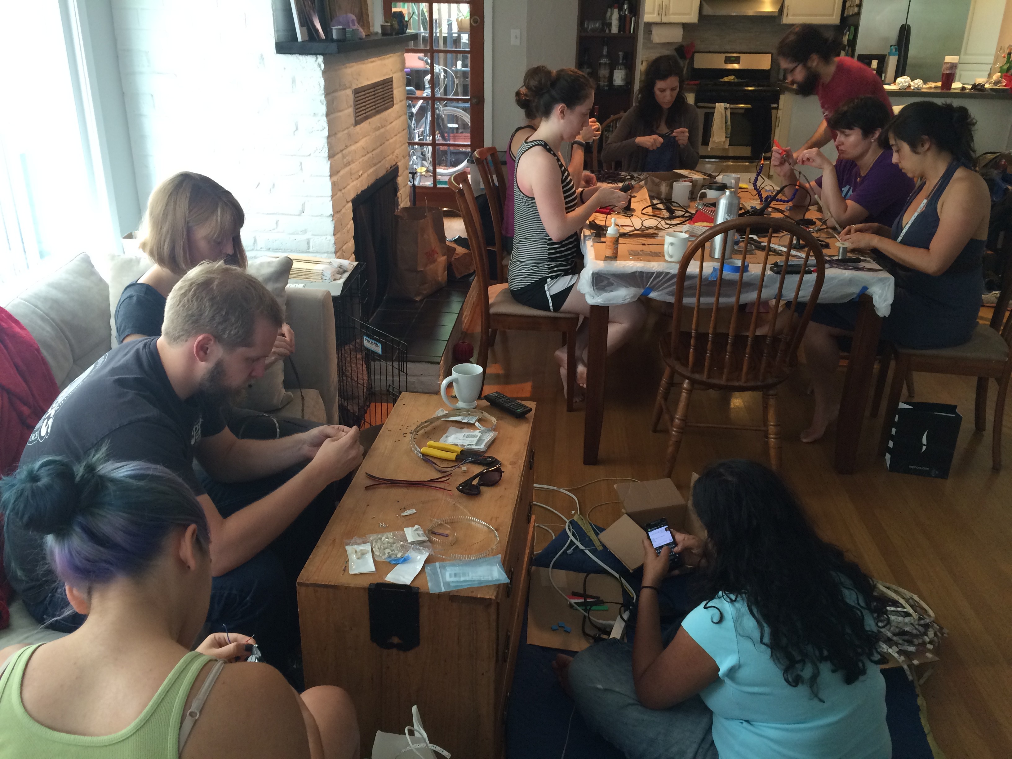
07/06/2015 at 22:19 • 0 commentsIs there a better way to spend 4th of July weekend than to build stuff? I don't think so.
![]()
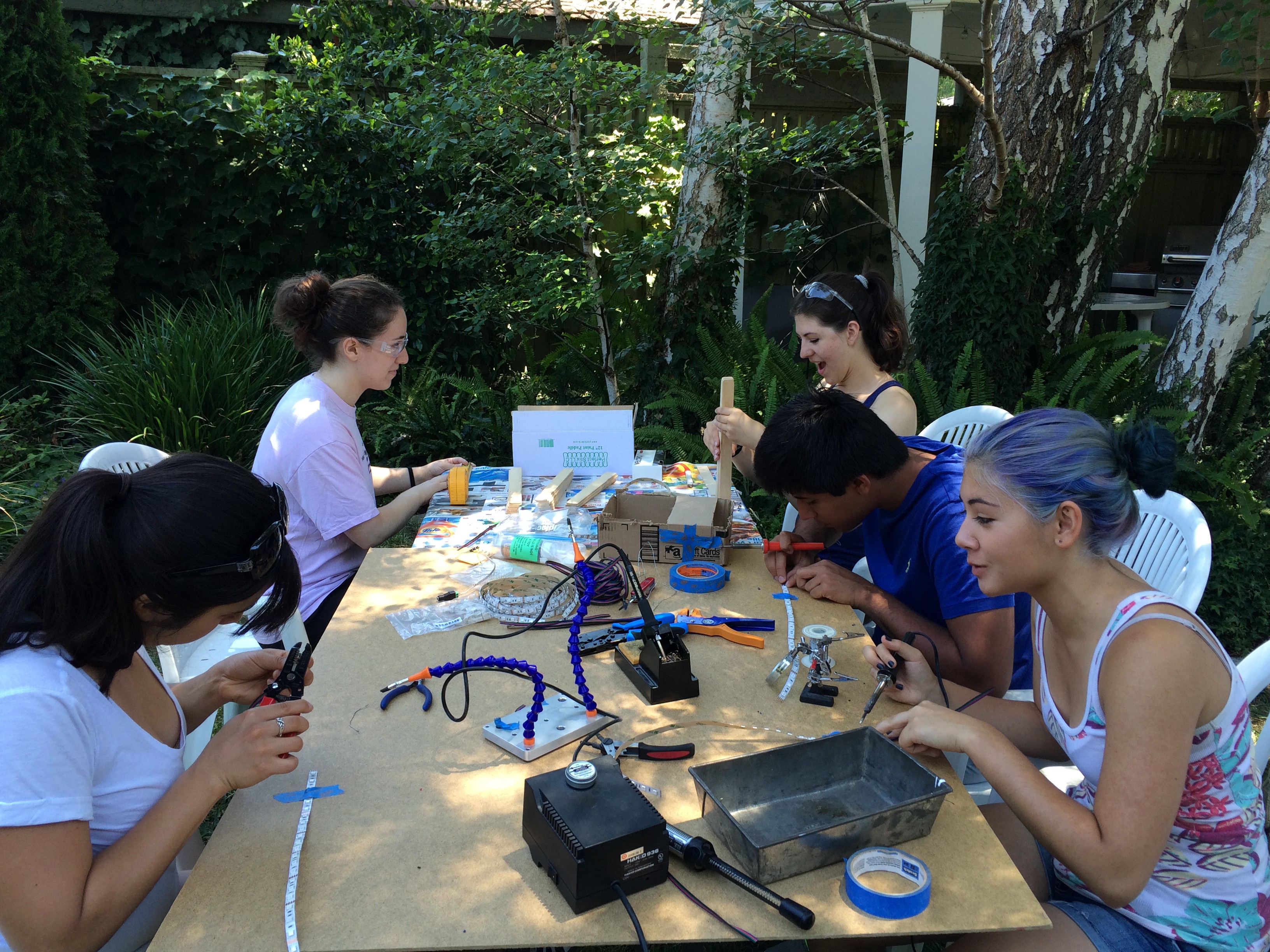
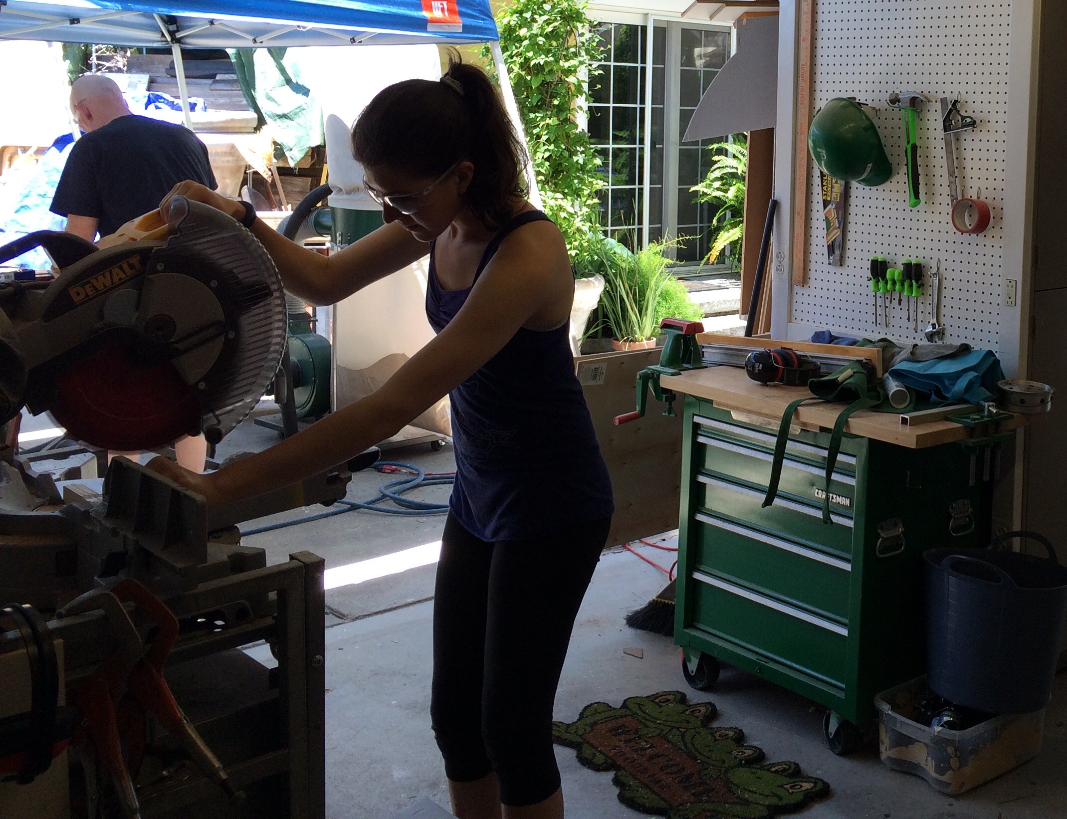
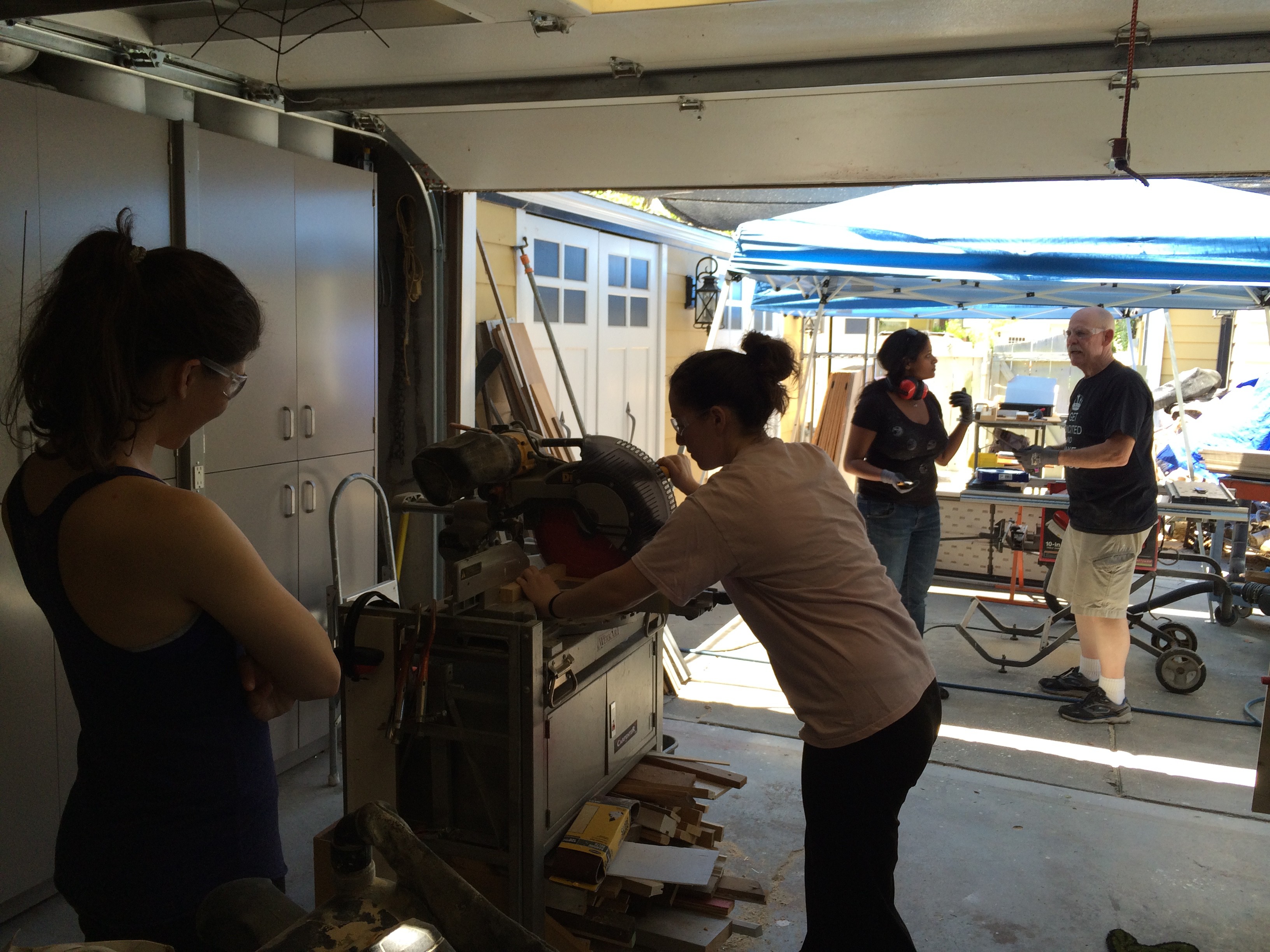
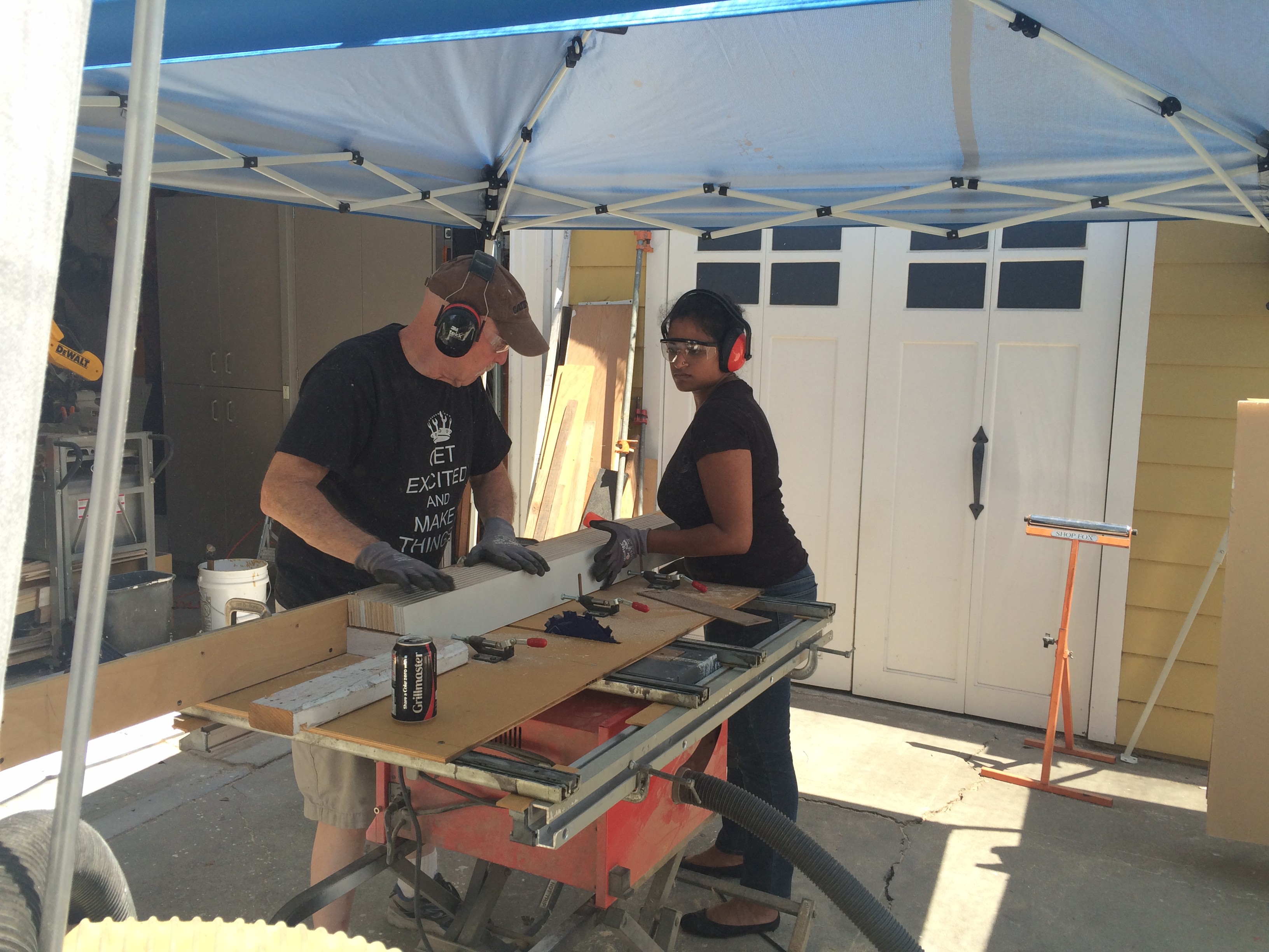
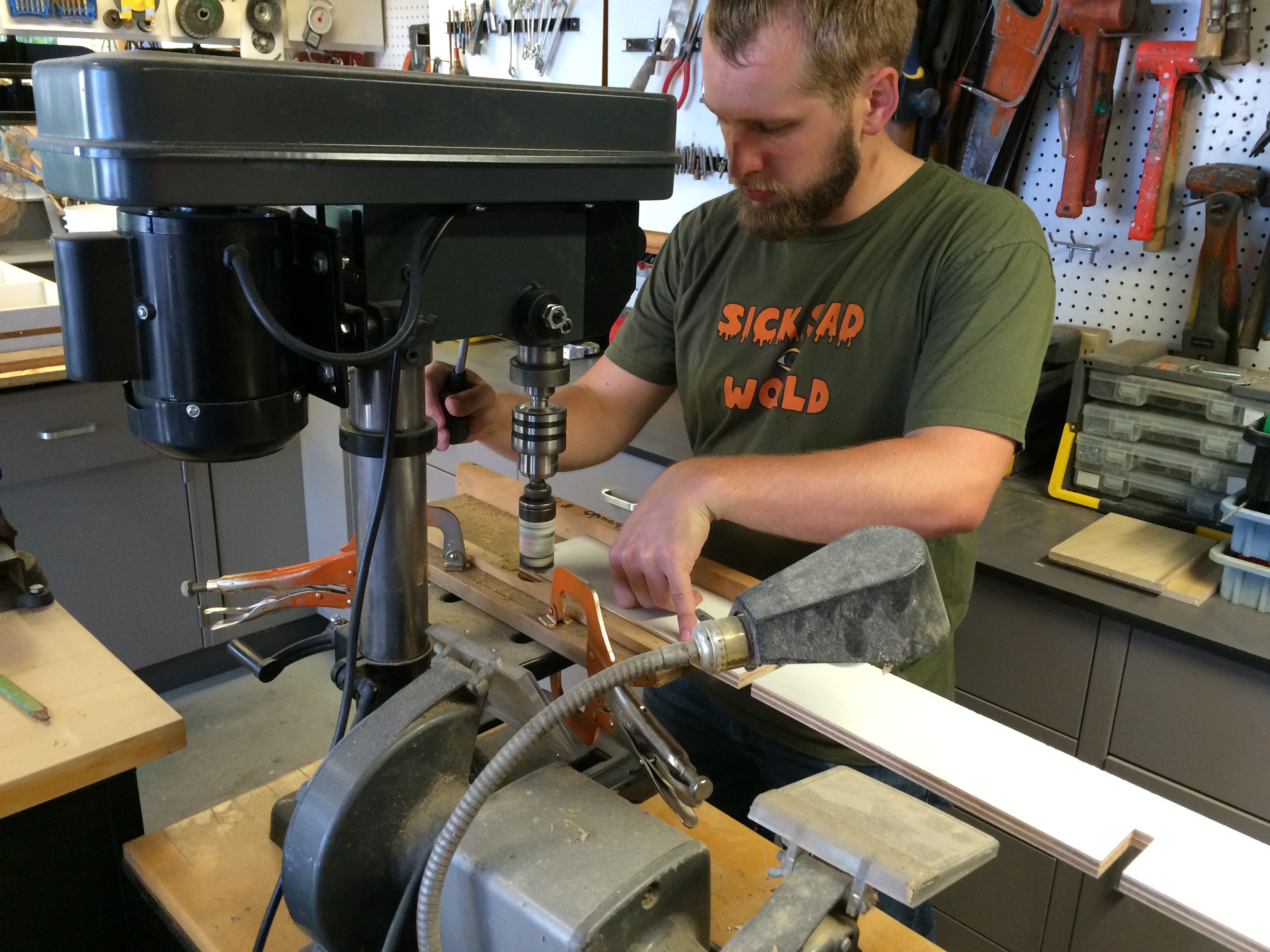
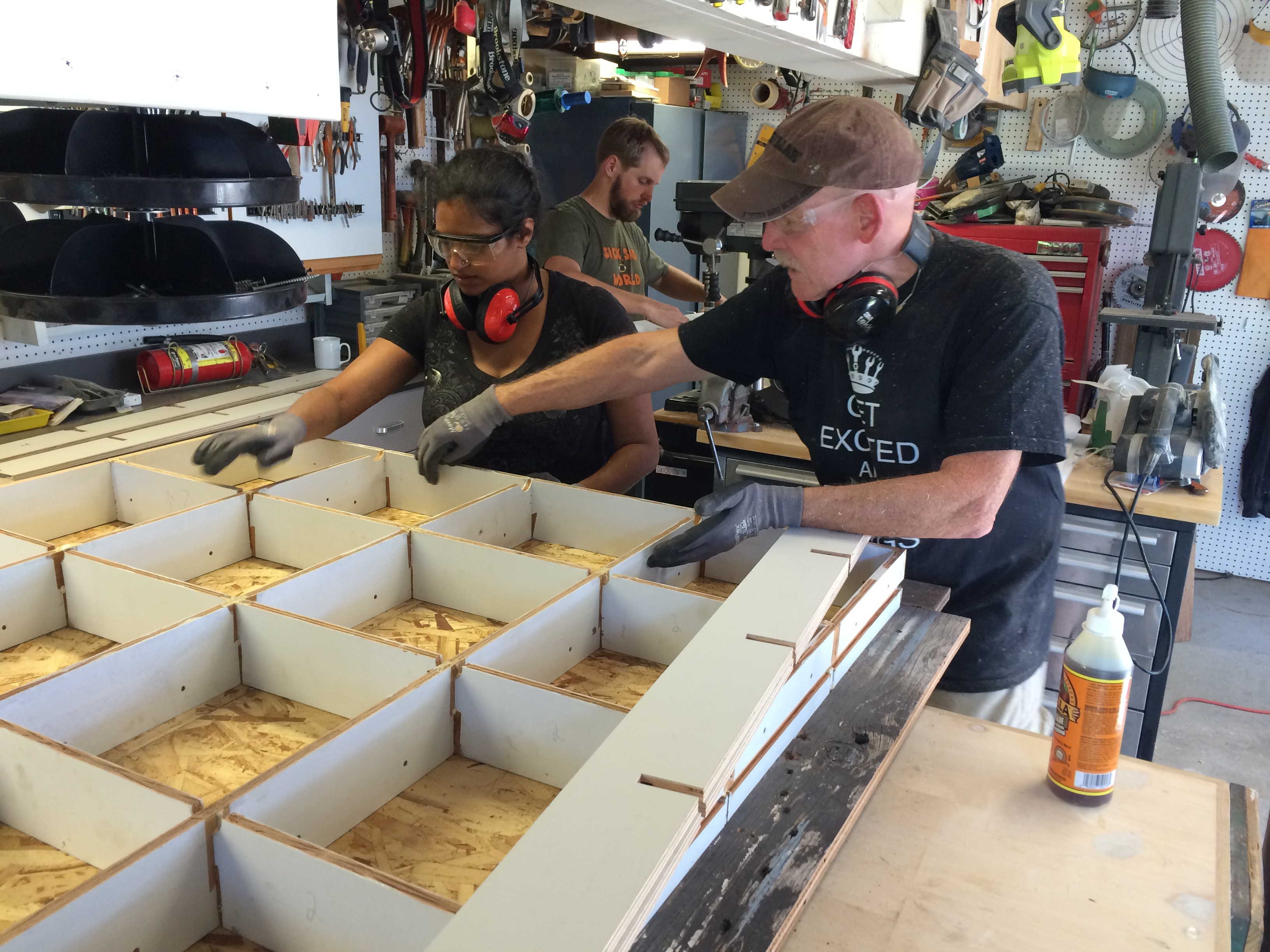
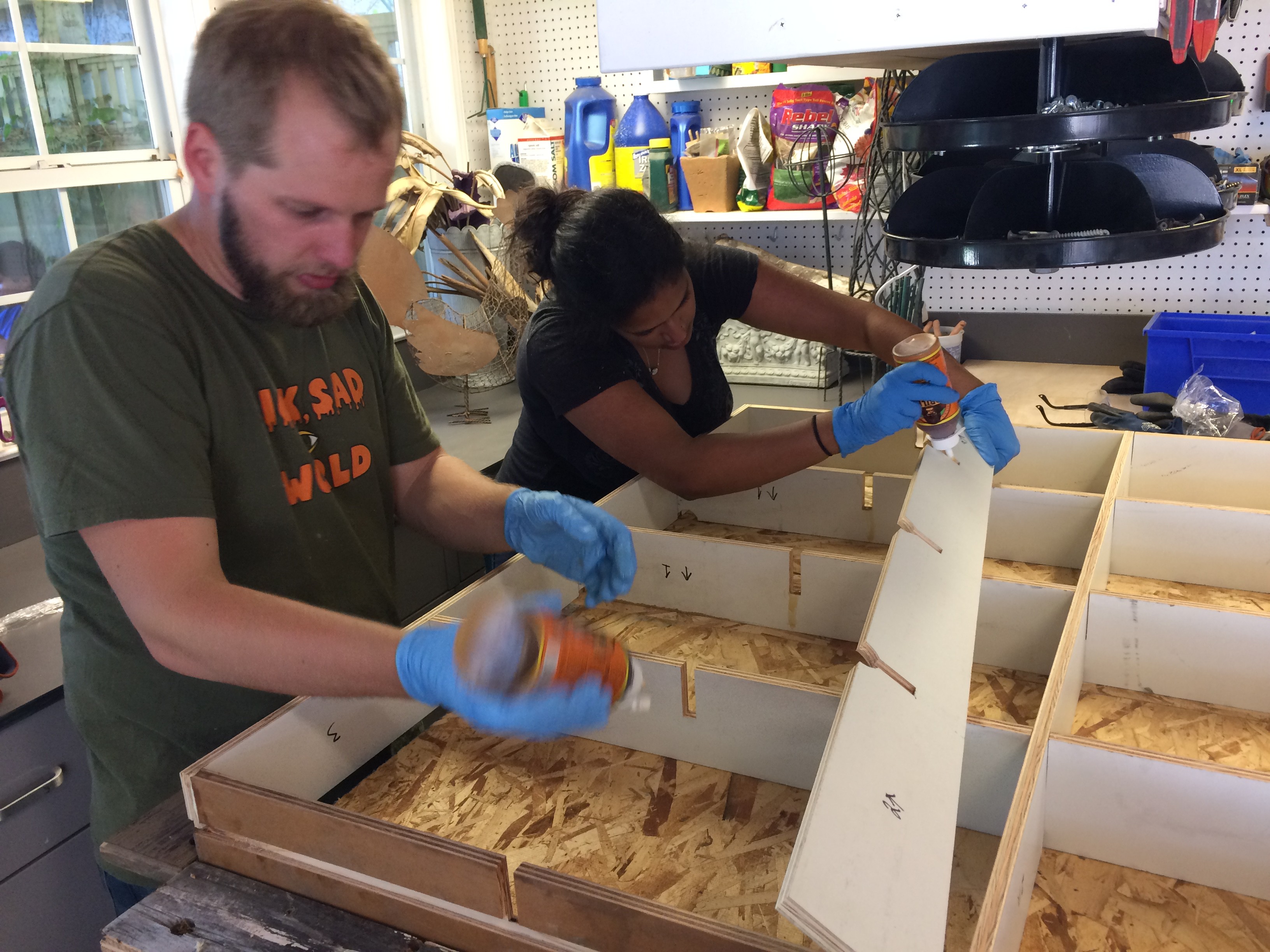
I was lucky enough to pull about 15 people together this weekend to start on full-scale production! We gathered at my Dad's workshop in San Jose, where we could use all of his big tools and benefit from his amazing old school maker skills. Many people in the group had never soldered or handled big machinery, but no one was afraid to step up and learn.
By the end of the weekend we had all 5 floor structures assembled (minus the plastic), at least 200 LED strips cut and soldered, lots of connectors crimped and many other small odds and ends handled. The next step is to start assembling the new run of PCBs which arrived today. In a few weeks we'll put it all together and finish with a dance party!
Here are some pics of the weekend build.
![]()
![Cutting LED platforms]()
Cutting LED platforms
![]()
A jig that notches 10 strips of wood at once.
![]()
![]()
![]()
Some assembly required
![]()
Completed floor sections!
![]()
![]()
Solder and crimping party!
![]()
QA - Testing completed LEDs
![]()
Just a handful of our LEDs
-
Non blocking Capacitive Sensing
06/19/2015 at 23:29 • 4 commentsI think I've finally created a reliable non-blocking capacitive sensor library for the Atmega!
![]()
The Problem
Originally I was using Paul Stoffregen's Capacitive Sensor library, which works great, except that the main program has to wait while it takes enough samples (~30) for a stable proximity reading. It's usually pretty quick, but when you're trying to poll 144 nodes at 250Kbps, this delay can add up significantly.
I had to find a way to get the capacitive sensor running "in the background". There is a dedicated cap sense chip that we could use, but I prefer the challenge of making it all work on one little chip. After several failed iterations the latest appears to be working well...so far.
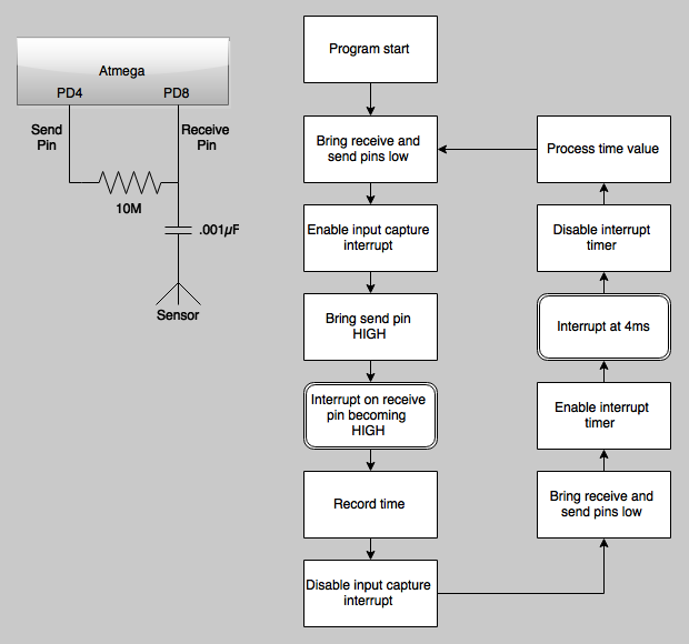
How capacitive sensing works
The capacitive sensor is basically an RC circuit with the person being a variable capacitor. The circuit looks something like this:
![]()
The process to detect someone's proximity starts by setting the send pin to high and then tracks how long it takes for the receive pin to go high. The closer someone is to the foil, the longer this will take (ther person acts as a larger capacitor in the RC circuit).
Paul Stoffregen's method is to create a while loop which waits for the receive pin to register as HIGH and then waits another 10µs for everything to stabilize before taking the next reading.
The non-blocking solution!
The solution came down to juggling a few interrupts to handle this entire process without blocking the main program execution.
![]()
The program basically works by using the Atmega's input capture unit (ICU) to take a timestamp every time the receive pin goes HIGH. Then it uses a timer interrupt (triggered in ~4ms) to process the timestamp and give the pins time to discharge before starting the process all over again.
Noise
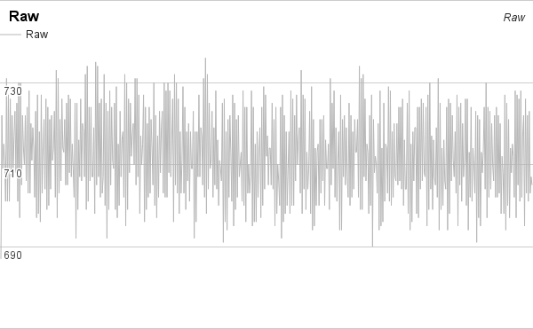
Trying to sense proximity (1+ inches / 25+ mm) with a capacitive sensor is inherently noisy since it can react to everything in its environment. I fought with this for a while -- playing with moving baselines, low pass filters, high pass filters, burning sage and chanting to the project Gods.
![]()
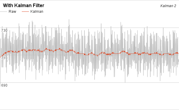
The solution came from implementing a simple 1-dimensional Kalman filter. The results were almost immediately a smooth and predictable line.
![]()
I also created a simple tool that will run the kamlan filter over a list of raw data, so I could play with various noise values offline.
See the code
-
Crystals and blocking timers
06/16/2015 at 23:46 • 0 commentsWhile putting the new boards through their paces we've found a couple small problems.
Crystals and bus communication
To keep the BOM down, the boards were designed without external crystals assuming the AVR's internal oscillator would be good enough for prototyping. The problem we've found is that the oscillator isn't accurate enough to talk on the RS485 bus any faster than 4800 baud. Even then, there are too many dropped packets to make communication viable for testing. The next boards will have crystals!
Capacitive sensors and blocking timers
I've spent the last few weeks working on building a capacitive sensor library that would not block main program execution. The idea was to set an interrupt timer that would check and update the sensor every 5 - 10μs. It's pretty much a non-blocking version of Paul Stoffregen's Capacitive Sensor. The code was lightweight and performed really well...that is, on a prototype that didn't have to do anything else. As soon as I integrated it into the main program, all communication on the bus stopped. Doh! It looks like the timer is still doing too much, too often and getting in the way of everything else.
I'm now going back to an earlier prototype that uses the AVR's input capture interrupt. The results are quite a bit noisier, but it should be more performant.
-
We have circuit boards!
06/07/2015 at 21:26 • 3 commentsOur first batch of circuit boards arrived and they are beautiful!
![]()
And with the boxes of fresh components, it was like [insert your favorite holiday here]!
![]()
Pretty quickly Cameron noticed the problem with the boards. We accidentally used a 32-VQFN footprint for the AVR instead of TQFP-32A. The good news is that Cameron had a few spare Atmega328s in the workshop with the correct footprint. Disaster averted and now on to find the next bugs before moving into full-scale production.
![]()
Interactive Disco Dance Floor
A large interactive disco dance floor with hidden capacitive sensors
 Now we screw the circuit board to the side of the box and plug the sensor wire into it.