Jeremy
-
Circuit Boards Ordered!
05/28/2015 at 17:23 • 0 comments![]()
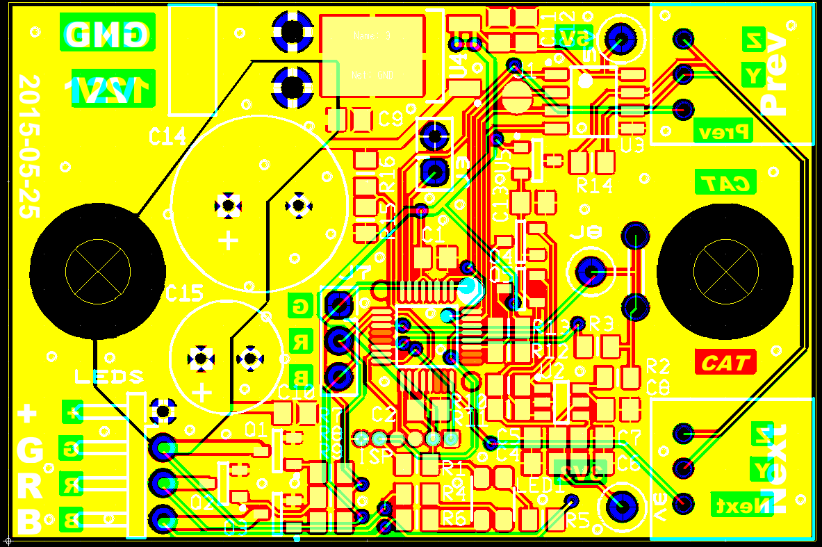
Our resident AVR/electronics expert Cameron, has been spending the last few weeks refining the circuit diagrams and patiently dealing with my lack of experience with a project of this size and complexity. Our conversations often go like this:
Jeremy: Look, I made a thing!
Cameron: Cool! I noticed <xyz>. Did you consider <abc>? You should really never do <123>...
Jeremy: *head explodes a little*
Cameron: *more experience tested advice*
Jeremy: *head expanding with knowledge...then asks stupid question*
Cameron: *patient reply*
Jeremy: *feeling smarter for knowing new things*
So for the past few weeks he's been doing double duty: finishing up the circuit board design and providing me with direction on the firmware and capacitive sensor programming.
After all that, we have very good news, we have ordered our first run of circuit boards! This run of boards will have extra circuitry that, hopefully, we won't need in the production run. We've been trying to figure out if the Atmega will be able to reliably handle the capacitive sensing or if we'll need to use a specialized chip (Azoteq IQS211).
The de facto Arduino capacitive sensing library blocks the execution of the main program while it's reading sensor data. This will significatly slow down how fast the nodes on the network will be able to communicate with the master. So we've added pads to the PCB for the specialized Azoteq chip, just in case. The good news is that the latest capacitive sensor libraries we've been writing are working really well. So I'm confident the next board will be much simpler.
-
Floor Construction
05/28/2015 at 16:51 • 0 commentsThe floor structure team met last Monday and we spent a few hours hashing out the final design ideas so we can spend the upcoming weekend building the first full-scale prototype!!!
![]()
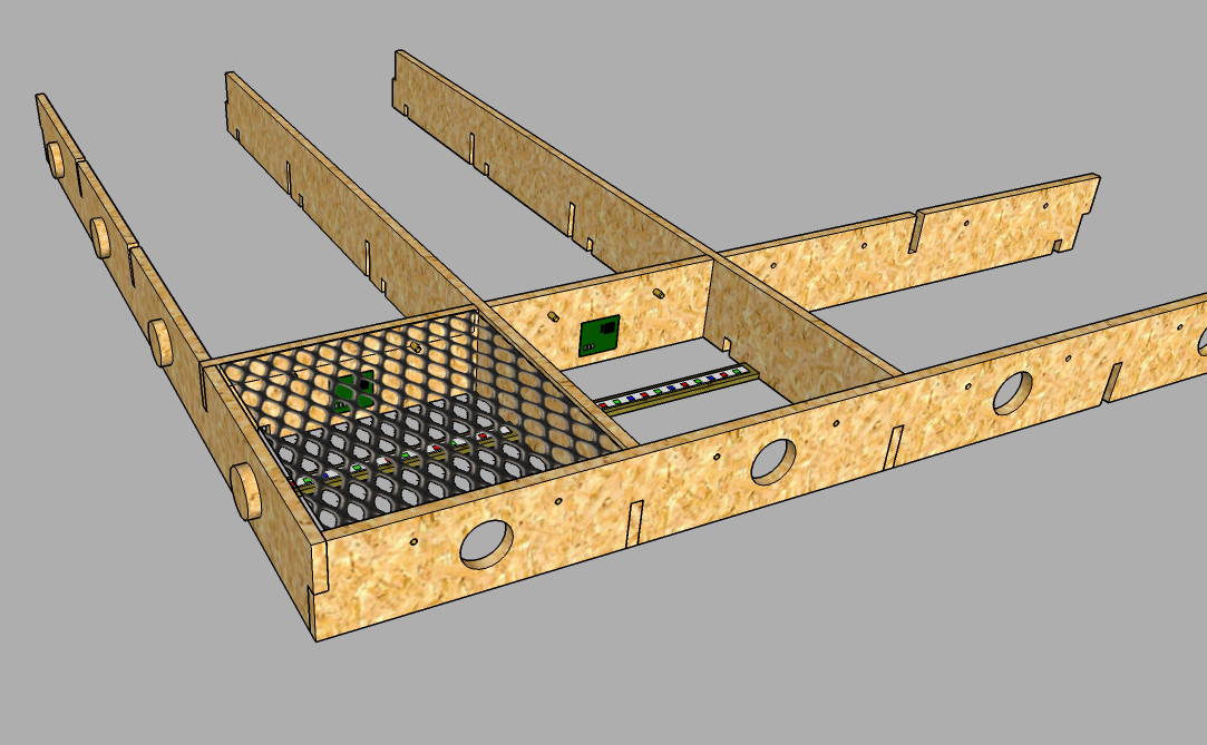
Here's what we came up with. The floor will still be made up of several 4' x 4' sections with 16 light-up squares in each. The biggest area of debate was how to connect them together and keep everything aligned.
The simplest answer was to have alternating pegs and holes around the perimeter that neighboring sections can mate with. Then we'll tie all the sections together with a modular frame that can be setup around the entire floor.
We're still working on how the frame will actually work. The simplest idea would be to use a simple ratcheting tie down strap around the floor. Although, we're working on something with wood planks and specialized clips. Stay tuned.
You can see the latest sketchup files in github.
![]()
Floor light-up cell with electronics and sensor
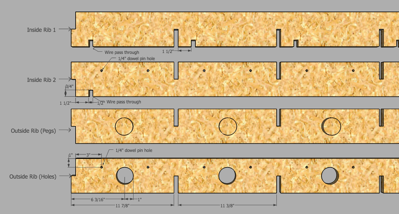
Cut dimensions![]()
-
Almost ready for full-scale construction!
05/15/2015 at 00:47 • 0 commentsThe last couple months have been BUSY. Here's an update on all of the things we've been working on.---------- more ---------
Floor Square Size and Plastic
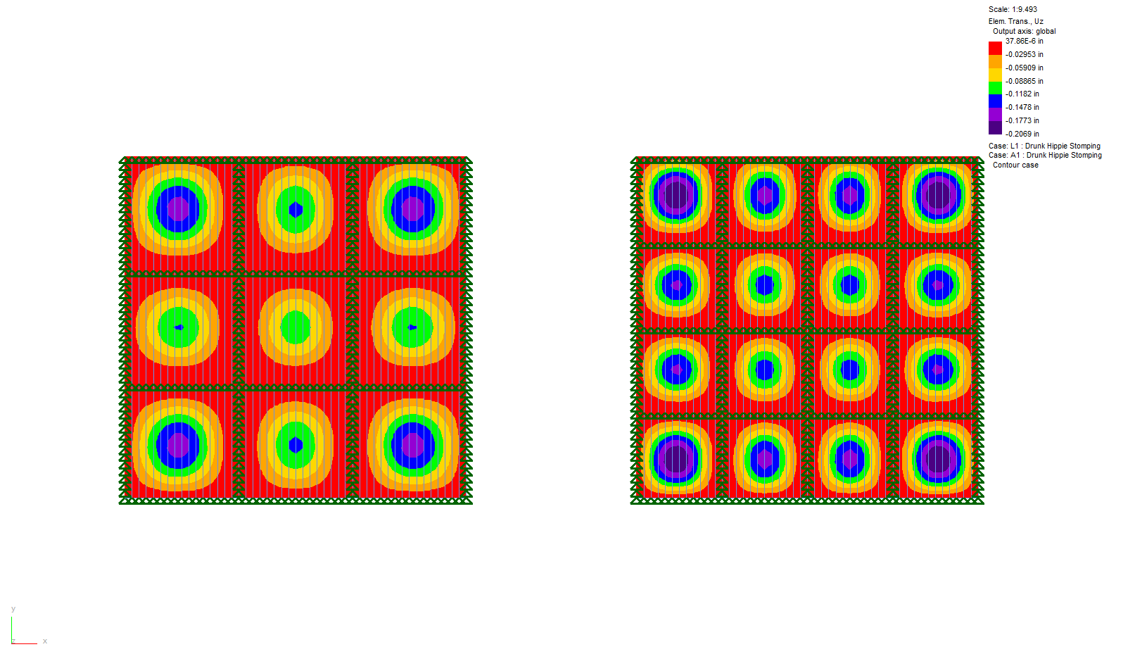
Originally we wanted the floor squares to be 14" x 14". Nick, who is a structural engineer by day, did some stress testing and found that using half-inch acrylic wouldn't be strong enough to reliably withstand the load of "the drunk hippie stomping" on it.
I also investigated using polycarbonate instead of acrylic; which would be much stronger. The problem is that semi-opaque polycarbonate does not come in 1/2" thick sheets. I tried laminating small polycarbonate sheets together (1 layer clear + 1 layer semi-opaque) but it always had air bubbles that disrupted the light.![]()
In the end, we're going with 1/2" semi-opaque acrylic over 11" squares. This now increases the number of squares from 81 to 144.
Plastic and the wood base
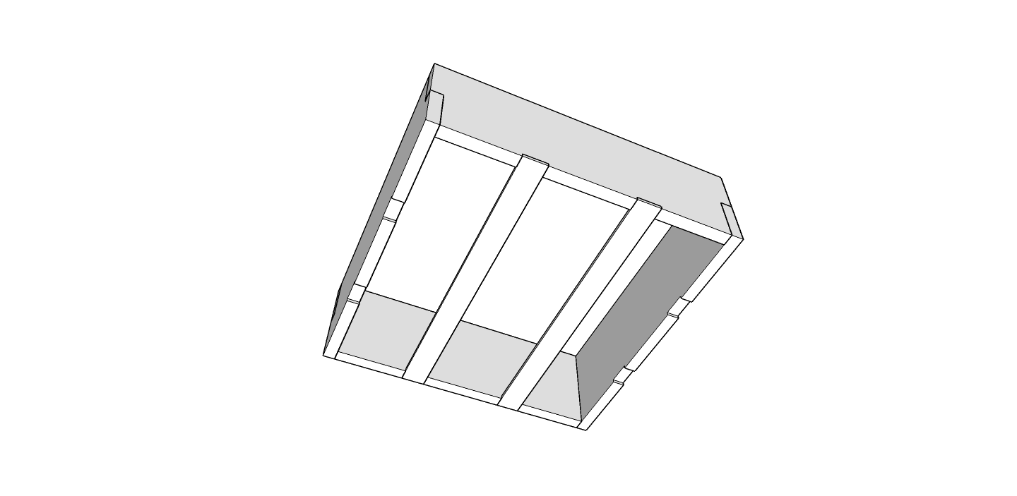
Next was figuring out how to attach the plastic to the wood base. We're still planning to break the floor into 4' x 4' sections, which will hopefully transport well and go together quickly. Each section will have 16 squares underneath it.
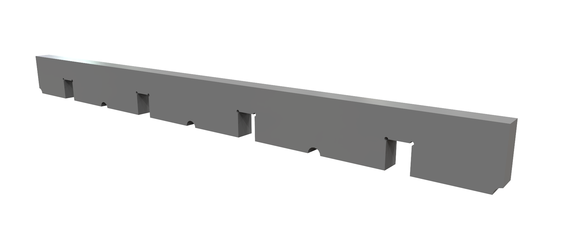
The base will be made of wood ribs that are notched so that they fit together into a grid. The inside ribs will be between 1/2" to 1" thick, with the outside wall being half that, so the border between squares is consistent across the floor.
![]()
Initially we wanted to be able to attach the plastic in a way that would be easy to remove. Unfortunately, all the ideas were either too complicated, not strong enough or might crack the plastic during a week of abuse. The plan now is to glue it to the base using an industrial adhesive, like E6000. Accessing the electronics will have to be done by removing the bottom base board.![]()
LEDs
Which brings us to lighting the whole thing. After testing many LEDs and looking at several sources, it seems that using LED strips will be the cheapest and easiest way to go. We built a scale test platform and tested several arrangements. The two options that work the best are:
1. Mounting 1 meter of the LED strip around the perimeter of the box. This uses 1A at max output per square.
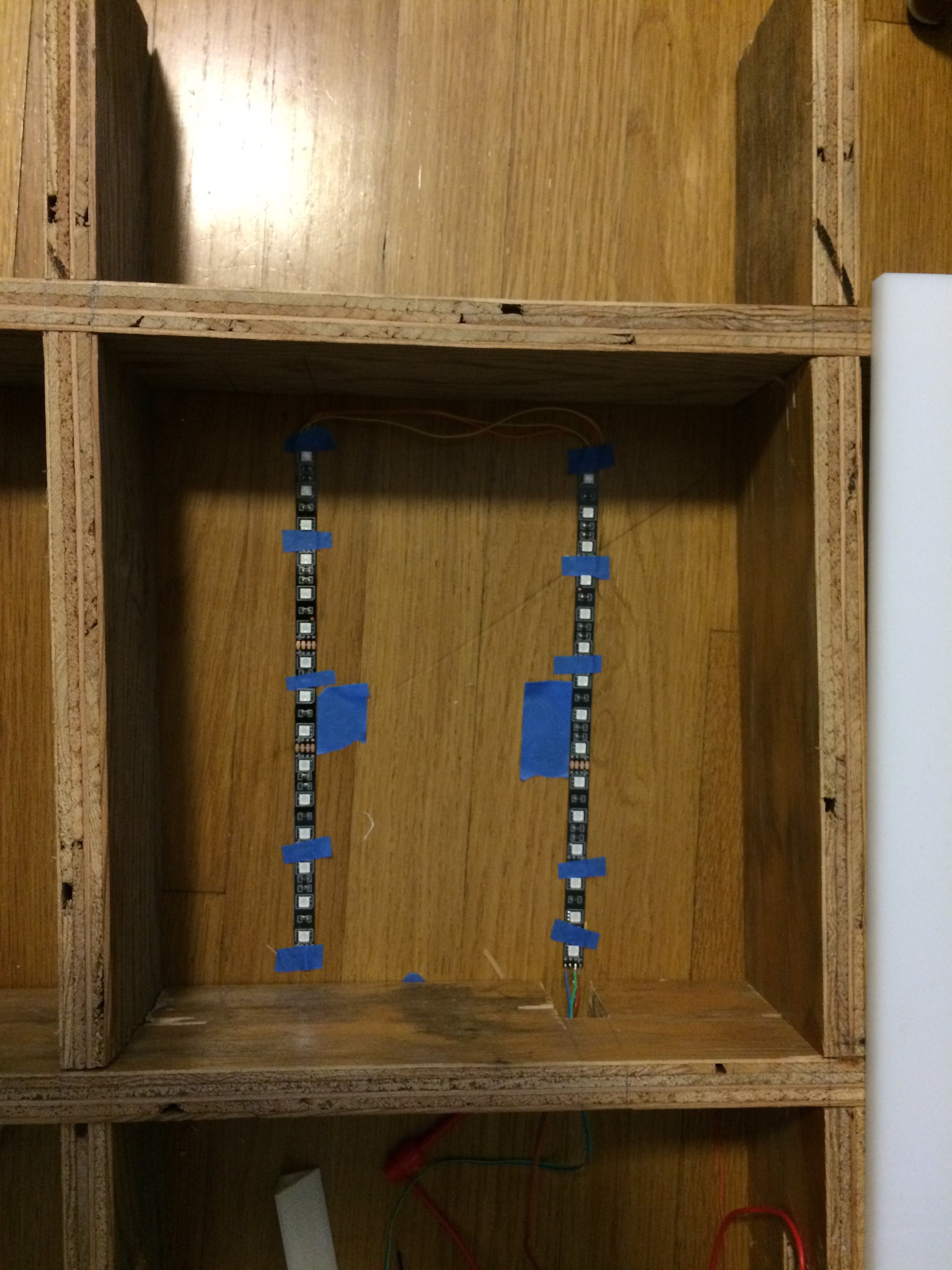
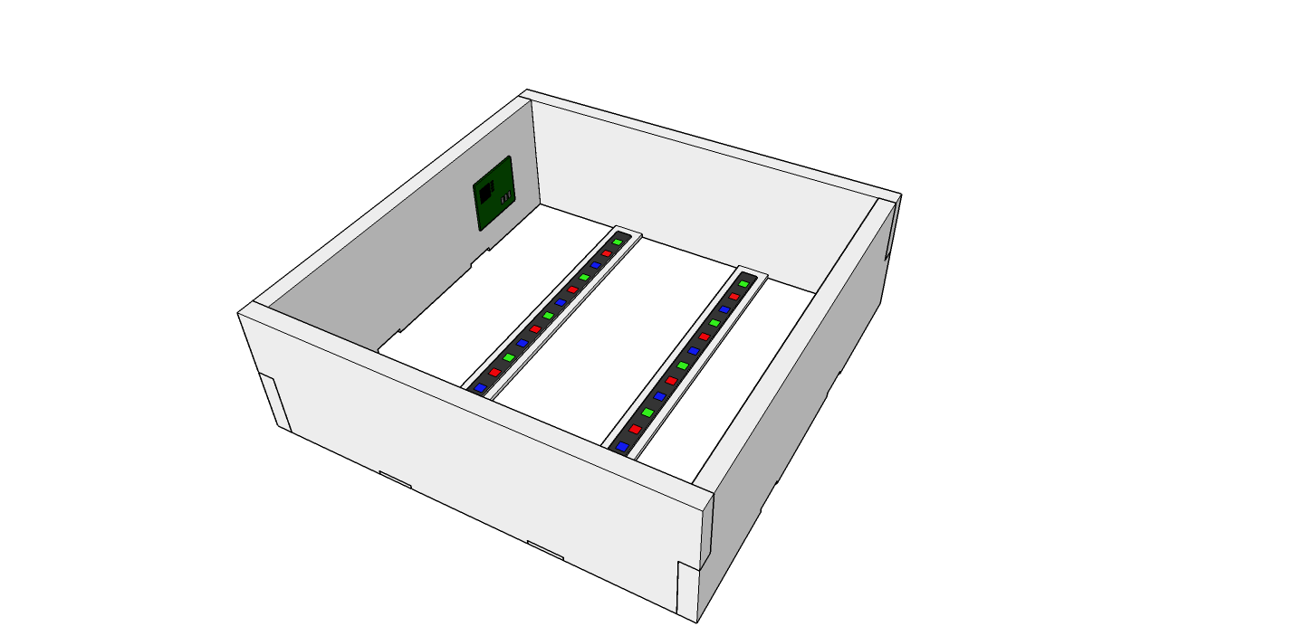
2. Mounting two 25cm strips on the bottom of the box, approximately 3" from the sides. This uses about 500mA at max output per square.
Both options produce approximately the same amount of perceived light through the plastic. The first option is easier to install, but needs twice the amount of juice. So we're going with the option number 2. This means that we'll need to put a couple of thin pieces of wood across the bottom of each square that the LED strips can mount to.
![]()
![]()
![]()
![]()
Mylar Reflective Film
I'm about to test what happens if I cover the bottom of the box with a mylar reflective sheet. I'm hoping this will help increase the light output coming through the plastic. My only concern is that it could also turn the squares into mini ovens and damage the electronics and LEDs. I'll have to find a way to test this as well.
Capacitive Sensor
Lastly, in this update is the capacitive sensor.
First, we've found that using chicken wire under the plastic as the sensor area is much more reliable than loops of magnet wire! This is cheap and much easier to setup than figuring out how to attach loops of wire to the underside of the plastic!
We're still using the Arduino CapacitiveSensor library for detecting if a person is standing on a square. This works, however the library requires a blocking action. With a network of 144 nodes, this can block communication and cause some latency issues. I've added some code to try to do the sensing when the node is not responding to the network and master will skip a node if it is taking too long to respond. This helps, but is not perfect. The plan is to write a custom library that will use timers or interrupts, so it will seem to happen in the background.
Next Steps
In the next couple weeks we're going to be finalizing the circuit board design and building the first 4' x 4' section! Stay tuned.
-
RS485 Bus Protocol
03/10/2015 at 07:36 • 0 commentsI finally got the disco floor slave/master network working end-to end. Here's how the protocol works (see README for more info).
There is one master and many floor cells (slaves) all running on an RS485 bus. Each floor cell is daisy chained to the next with a single 'enable' wire, for automatic address registration. There are 3 phases in the floor life cycle: addressing, status, updating.
- Addressing phase
- Master makes the enable pin on first floor cell HIGH and sends a global message with the current highest address (1). (master will repeat this message every 500ms that the bus is idle)
- The first node...
- See's the enable pin is HIGH
- Receives the address message from master
- Increments the address by 1 and responds to master with this address (2).
- Makes the enable pin on the next floor cell high
- Master responds with this new address. (and repeats every 500ms)
- Repeat 1 - 4 for each node on the floor.
- Once the bus is idle for more than 5 seconds, master moves onto the status phase
- Status phase
- Master sends a global message asking for nodes to report their status.
- First node responds with it's status, which includes
- Is it fading
- Does the capacitive sensor detect anything
- It's current color
- What color it's fading to (if it's fading)
- Each node waits until the node before it reports status before sending it's status.
- If a node does not respond after 500ms, master sends another status request for all nodes from that node forward.
- If it still does not get a response, master skips that node and asks for status from the next node forward.
- Once all nodes have responded, master moves to the update phase.
- Update phase
- Master sends a program update to nodes. Either set a color or fade to a color
- After master has finished updating nodes, it repeats the status phase.
This has all been prototyped with an arduino as the master node. The next step is to update the nodejs computer program to talk to the nodes directly.
- Addressing phase
Interactive Disco Dance Floor
A large interactive disco dance floor with hidden capacitive sensors