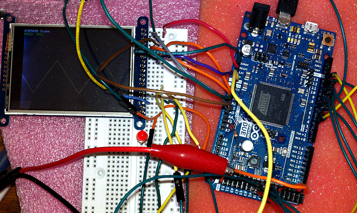
The arduino library supports A/D conversion at about 13 KHz, not fast enought for a useful audio-rate oscilloscope. Rewriting the acqusition loop to directly access the ADC reqisters speeds up conversion (including loop overhead) to about 688,000 samples/sec, a considerable improvement. The sampling loop becomes quite short. If we define registers and constants as follows:
#define ADC_MR * (volatile unsigned int *) (0x400C0004) /*adc mode word*/
#define ADC_CR * (volatile unsigned int *) (0x400C0000) /*write a 2 to start convertion*/
#define ADC_ISR * (volatile unsigned int *) (0x400C0030) /*status reg -- bit 24 is data ready*/
#define ADC_ISR_DRDY 0x01000000
#define ADC_START 2
#define ADC_LCDR * (volatile unsigned int *) (0x400C0020) /*last converted low 12 bits*/
#define ADC_DATA 0x00000FFF
Then the sample loop becomes:
ADC_CR = ADC_START ;
  for (i=0; i<320; i++){
    // Wait for end of conversion
    while (!(ADC_ISR & ADC_ISR_DRDY));
    // Read the value
    analog_data[i] = ADC_LCDR & ADC_DATA ;
    // start next
    ADC_CR = ADC_START ;
  }
For TFT display connections, look at the Adafruit tutorial, and consult the source code above. I used the following with the line//#define USE_ADAFRUIT_SHIELD_PINOUT in the file Adafruit_TFTLCD.h commented out.
// The control pins for the LCD can be assigned to any digital or
// analog pins...but we'll use the analog pins as this allows us to
// double up the pins with the touch screen (see the TFT paint example).
#define LCD_CS A3 // Chip Select goes to Analog 3
#define LCD_CD A2 // Command/Data goes to Analog 2
#define LCD_WR A1 // LCD Write goes to Analog 1
#define LCD_RD A0 // LCD Read goes to Analog 0
#define LCD_RESET A4 // Can alternately just connect to Arduino's reset pin

// With shield defined (from pin_magic.h)
// LCD Data Bit :    7    6    5    4    3    2    1    0 (LCD data pin)
// Due pin #    :    7    6   13    4   11   10    9    8 (board pin #)
A minor rewrite displays the frequency of the periodic input wave every second.
 Bruce Land




 Guillermo Perez Guillen
 Makerfabs
 agp.cooper
how to show the signal on serial osciloscope sir? please help me