 agp.cooper
Adding an LCD Display
What is so hard? Just use the LCD library. Actually the problem is hooking it up in a semi-permanent way rather than the using the LCD library.
Issues
- Which pins to use
- Controlling the LED
- Controlling the contrast
When I first layout the strip-board for the display adapter I first used the standard pin numbers as shown below:
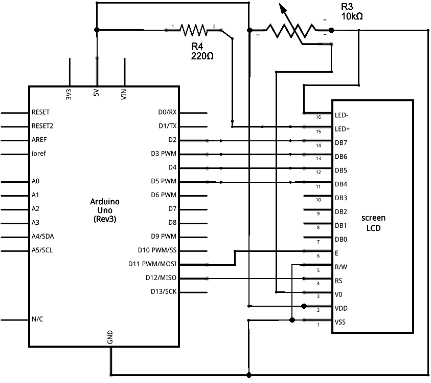
Except I used D6 and D7 for "E" and "RS", and D8 to control the LED power.
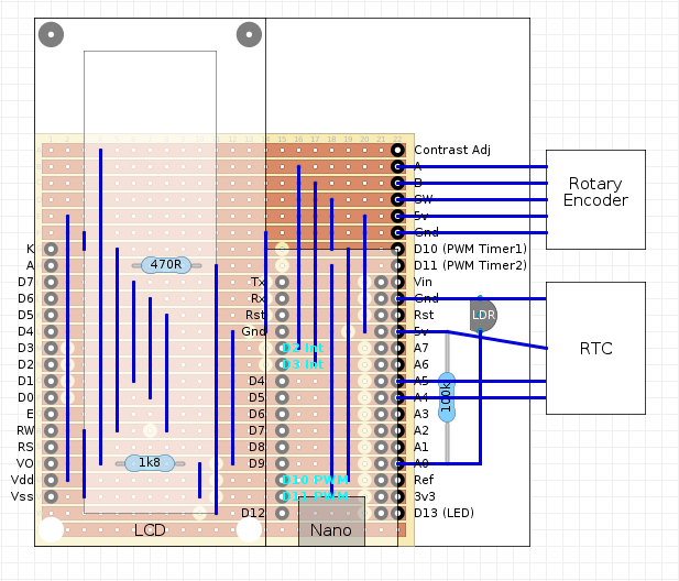
The first problem was adding a rotary encoder. The first rotary encoder code used two rising level interrupts and on the Uno/Nano you have to use D2 and D3. So I shuffled all the LCD pin number down by three (D4 was to be used for the switch). Leaving D12, D13 (the LED) and the analog pins free.
As the design progressed I realised it would be nice to keep the interrupt and PWM pins free, and I decided to use polling as I had to deal with switch bounce anyway.
For contrast a 1k8 resistor to ground work okay but access for contrast adjustment was provided.
Here is my strip-board design:
Magic
Discussions
Become a Hackaday.io Member
Create an account to leave a comment. Already have an account? Log In.