Alan Kilian
-
KiCad project on GitHub
07/06/2015 at 15:46 • 0 commentsI posted the KiCad project files on GitHub if anyone is interested.
-
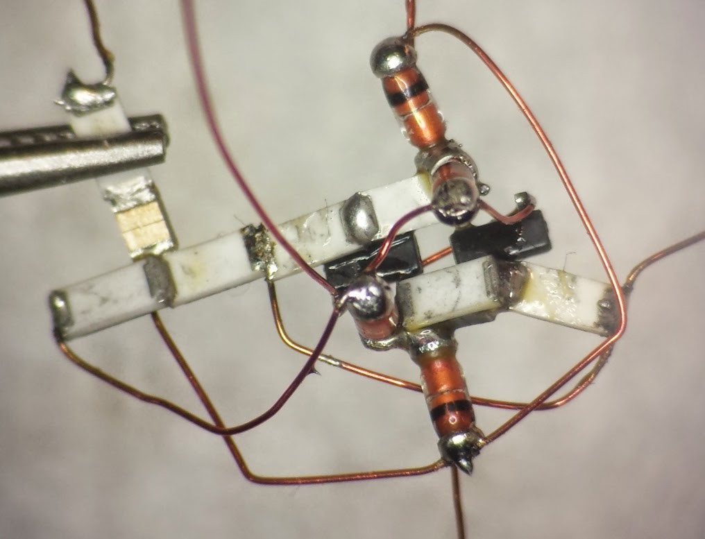
Photo of the "spine"
07/05/2015 at 20:26 • 1 commentHere's a photo of the "spine" with air wires.
This took me about 30 minutes to solder.
it seems fairly sturdy when I bend around on it, so I think it'll hold up.
Next is to make the two outer three-component groups, attach them to the spine, and then..... TEST!
-
"Final" layout done.
07/05/2015 at 18:35 • 0 commentsAfter moving things around and building test circuits for just about forever, I think I've finally got a layout I can live with.
I suppose I should put the binary files on GitHub or something.
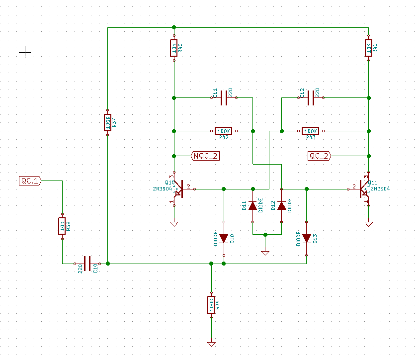
In the mean time, here's the schematic and layout for one flipflop.
![]()
The white lines are "air" wired that will be magnet wire. They are things like ground +9V0 and some other signals that I couldn't get routed perfectly. I also will wire up an input signal and two output signals.
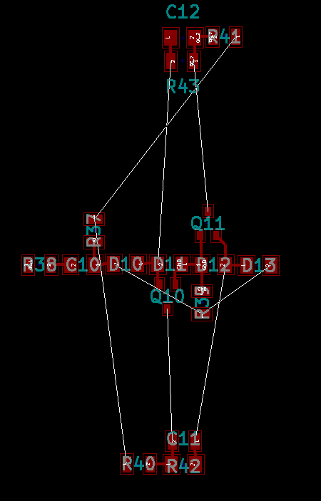
![]()
I like having the central "spine" of 10 parts and the two "leave" segments of three parts each separated by wires.
When I connected them all together "hard" the unit was too fragile.
I'm going to rig up a wire structure that I can glue the three parts to to hold them together securely.
That's the next step.
-
KiCad and the missing Ripup tool.
04/10/2015 at 01:48 • 1 commentI spent about two hours trying to figure out how to rip up traces, watching Youtube videos, looking at websites that didn't match my vesion of KiCad.
I even BUILT THE DAMN THING FROM SOURCE and I just could NOT figure out where the damn ripup tool was!!!
Then, about 15 minutes into a Youtube video, there, right in the middle of everything, was......
(you hit the delete key to ripup. There's no graphical deal or pull-down menu item!)
So, I feel like a complete dunce, but I got some things done.
I built a schematic of one flipflop.
I added footprints to the schematic.
A created a PCB.
I moved parts around to get the best layout I could.
I'll look at it a bit more again and then I think I can start soldering flip flops together and it'll go pretty smoothly.
I'll add the kicad files wherever I can find to add them. ;-)
-
Back to design.
04/05/2015 at 21:48 • 0 commentsI spent a few days soldering parts together trying to rearrange the schematic in my head to make building easy.
I made plenty of nonworking flip-flops, so I went back to basics.
1) Install KiCad
2) Enter the schematic of one flip flop
3) do a PCB layout pretending I don't have a PCB so i can get all the parts in the right order and connected together properly.
4) Start soldering!
I'm on step #3 and I'll post the KiCad files soon.
-
It's ALIVE!!!
02/24/2015 at 23:16 • 0 commentsI got a chance to power-up the first divide-by-two and it actually works!
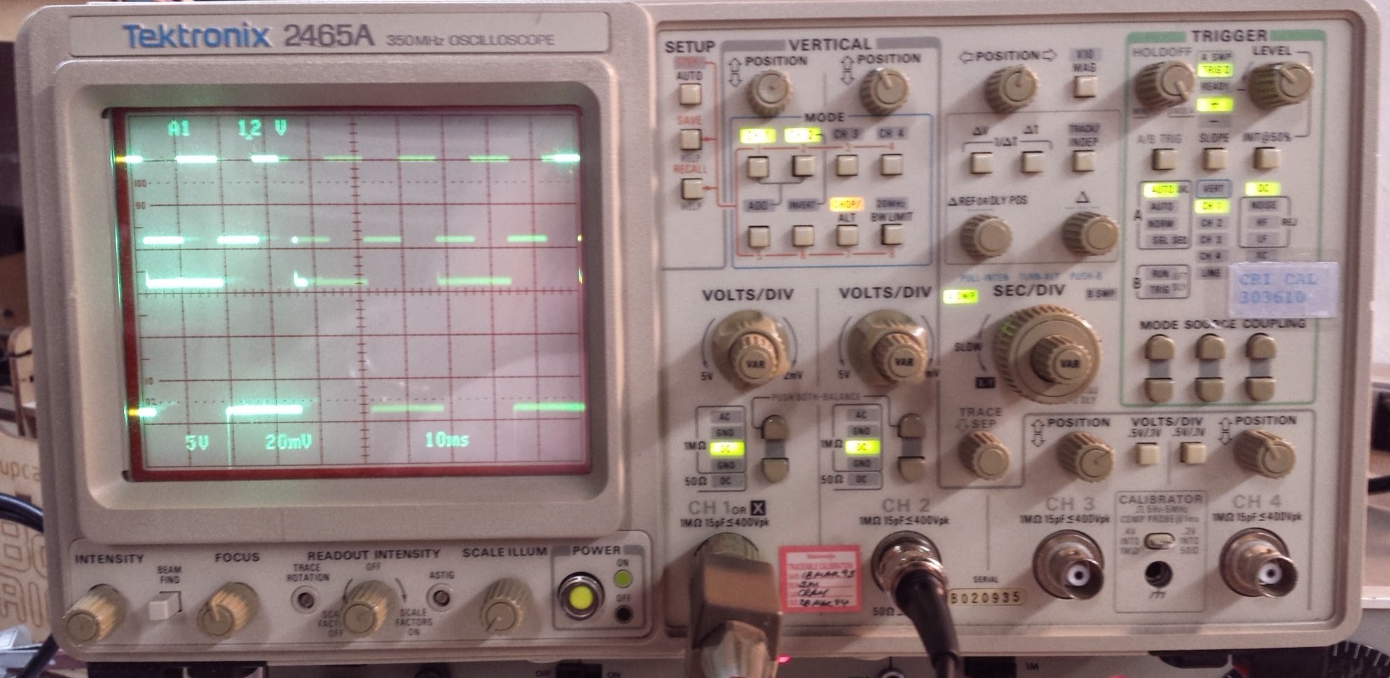
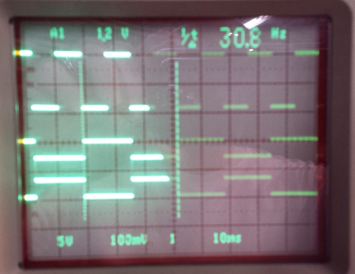
I've got both output wires soldered on the wrong place, but when I scope the right place, I can see it flipping and flopping! Top trace is a 9V 60Hz signal from the signal generator. Lower trace is one end of the divide-by-two running at 30Hz just as expected. The amplitude isn't right since I've got the wire on the wrong place, but it's working.
![]()
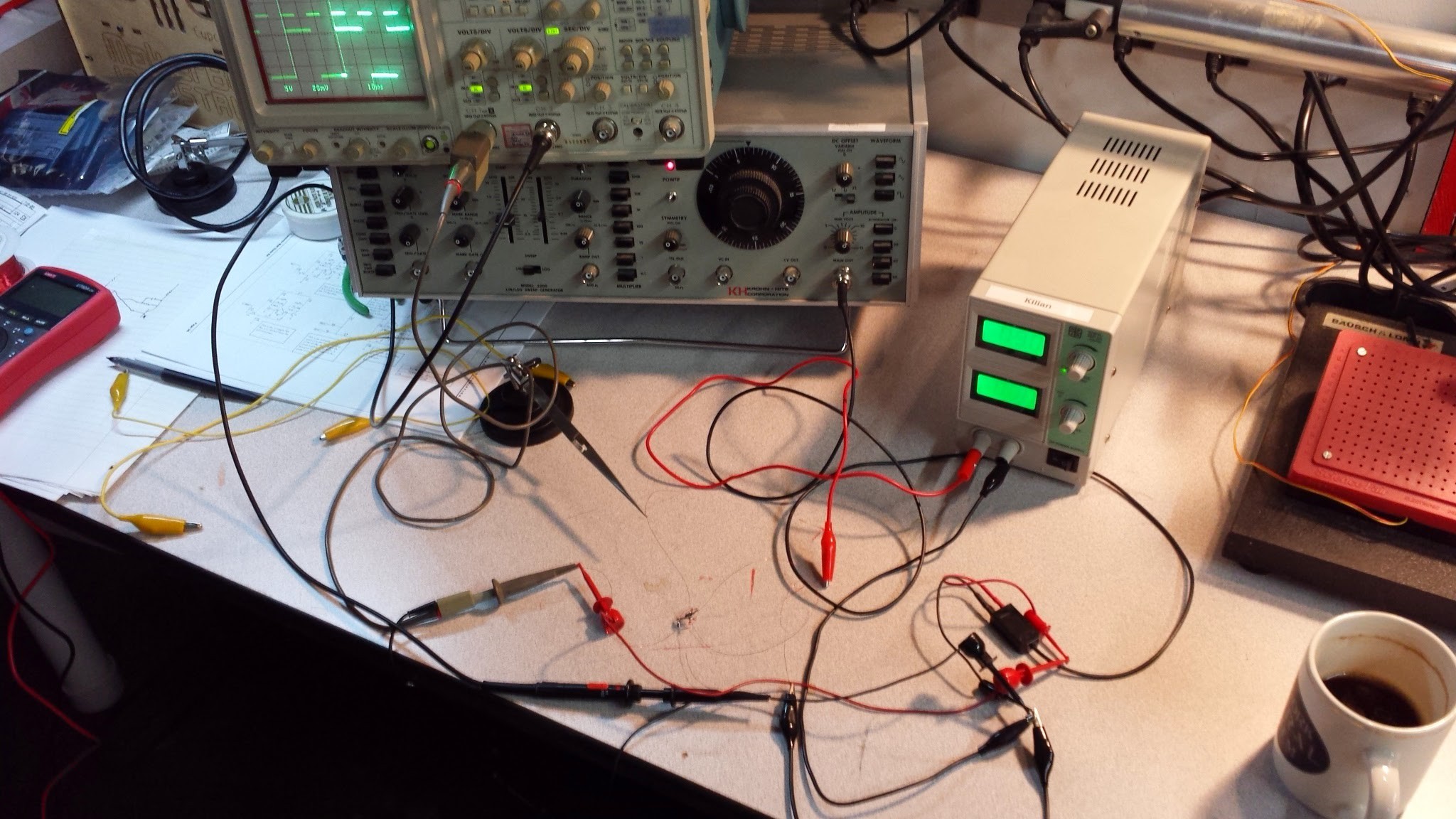
Here's the monster wire-nest of testing:
![]()
Here's a three-trace image showing the input at 60HZ, the normal output at 30HZ and the inverted output at 30HZ:
![]()
Sorry about the photo quality. I'll do better in the future.
So, IT'S WORKING!!! Now I'm really in trouble.
-
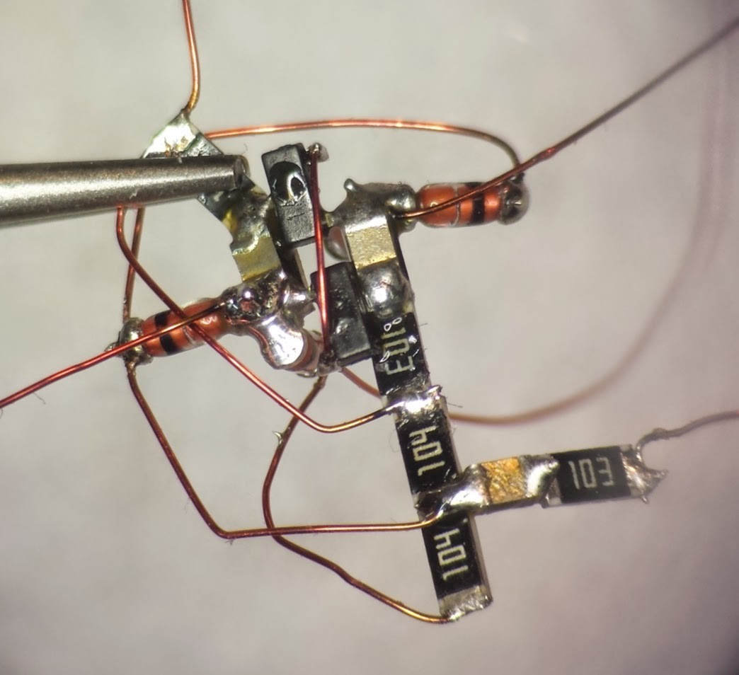
First divide-by-two complete.
02/18/2015 at 00:03 • 0 commentsOh, GOD, this was crazy. It took me about two hours to get this together.
now I have to test it and see if it actually works.
![]()
![]()
-
No progress.....
02/14/2015 at 20:44 • 0 commentsWith all the darn SNOW here in Cambridge, I haven't been able to get to my lab at Artisan's Asylum, and I'm just buzzing waiting to get back to finish and test the first divide-by-two unit.
-
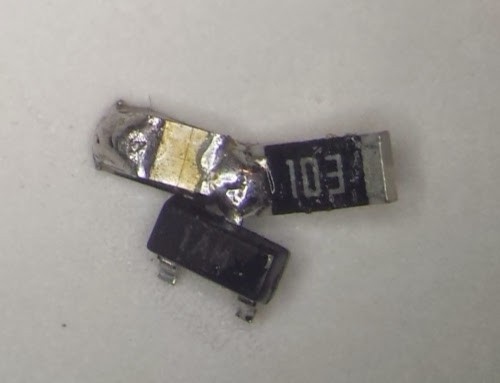
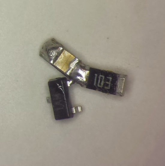
First mess up. took me 10 minutes to make a mistake.
02/08/2015 at 21:39 • 0 commentsDid anyone notice I soldered that transistor in wrong?
Here's what it should look like.
![]()
I can see that testing each flipflop after assembling and before adding to the final circuit is going to be critical.
-
Rediculous soldering ensues.
02/08/2015 at 21:20 • 0 commentsWell, I got the first FOUR parts together and it went fairly well.
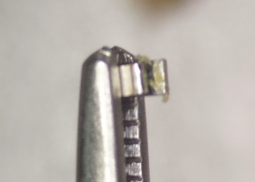
I decided to put C12 and R43 on top of one another since they are in parallel.
I stacked them in the reverse tweezers and added a little dollop of flux.
![]()
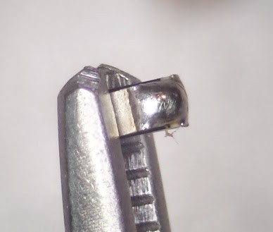
Then a touch of solder.
![]()
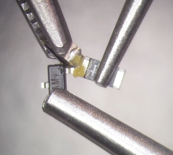
Next I arranged R41 and Q11 in two more "third-hand" with reverse tweezers and more flux.
Add heat and solder.![]()
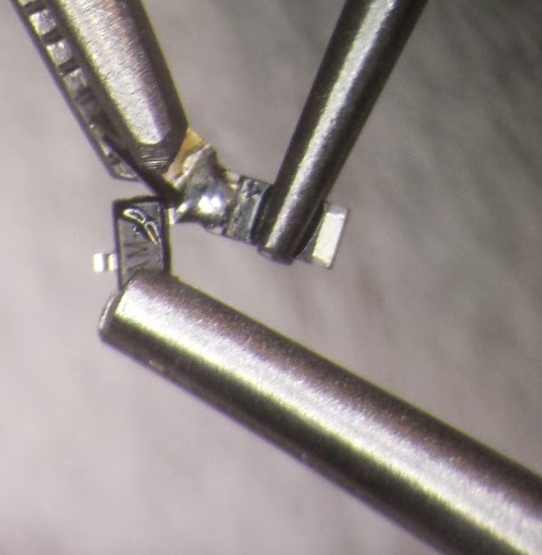
This is the result. The first complete net of the project.![]()
![]()
Point-to-point SMT Transistor clock.
Trying to hand-assemble a free form SMT transistor clock. Likely fail.