Close
0%
0%

ATTiny programming jumper plate with an Arduino

A simple board for programming ATTiny 2313/4313 and 45/85 microcontrollers using an Arduino and ArduinoIDE

Similar projects worth following
A simple board with jumper connections to an Arduino to program either an ATTiny 4313/2313 or a smaller ATTiny 45/85 (selection made with a simple switch). I made the device after reading this (http://www.instructables.com/id/Arduino-ATtiny2313-Programming-Shield/ ) Instructable and the following blog entry (http://highlowtech.org/?p=1229 ).

Using their designs, seeing that the 45/85 variety compared to the 2313/4313 only differ in programming with the ground pin, I designed my version presented here.

I will also include steps to upload the "Blink.ino" to both the 85 and 4313 and how to set up Arduino IDE appropriately on Linux (Ubuntu 14.04 on a basic Intel i3-4330 device).

If anyone would like to question why use the ATTiny chips, the main reasons are size and cost.

I am making a fridge controller (thermostat I suppose) for my parent's Whirlpool fridge. This appliance has a broken PC board and Whirlpool quoted a not guaranteed repair of $350. Since a fridge is essentially a timer that monitor's temperature and then appropriately activates a compressor, I was going to just make my own PC board with an Arduino.

After deciding on the best design for the controller I realised I only needed 2 binary inputs, an analogue input and two binary outputs. I also wouldn't need a significant clock speed either (the ATTiny's run at 1MHz with no trouble) and so decided to use an ATTiny4313 that I had lying around.

Below are some price comparisons to prove my point. The fact that you can work with the microcontrollers themselves (no USB port and PSU's etc.) increases the thought required but vastly improves the application flexibility too.

Arduino UNO R3 - $25

ATTiny2313 - $1 to $4

ATTiny4313 - $1 to $3

ATTiny45 - $1 to $3

ATTiny85 - $1 to $3

  • 1 × Protoboard
  • 1 × 10x2 pin socket mount
  • 1 × Red LED
  • 1 × Yellow LED
  • 1 × Resistor for LEDs' ground connection (1k etc.)

View all 11 components

  • 1
    Step 1

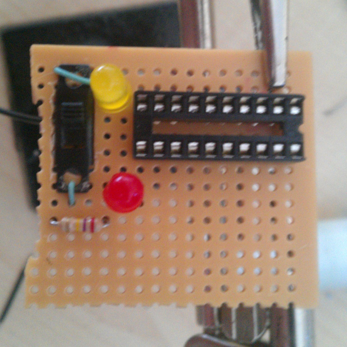
    Add the resistor and LEDs, along with the socket mount to the protoboard for the first bit of soldering according to the circuit shown on the project Home Page. The green wires shown just support my switch (claimed from a broken Christmas hat).

  • 2
    Step 2

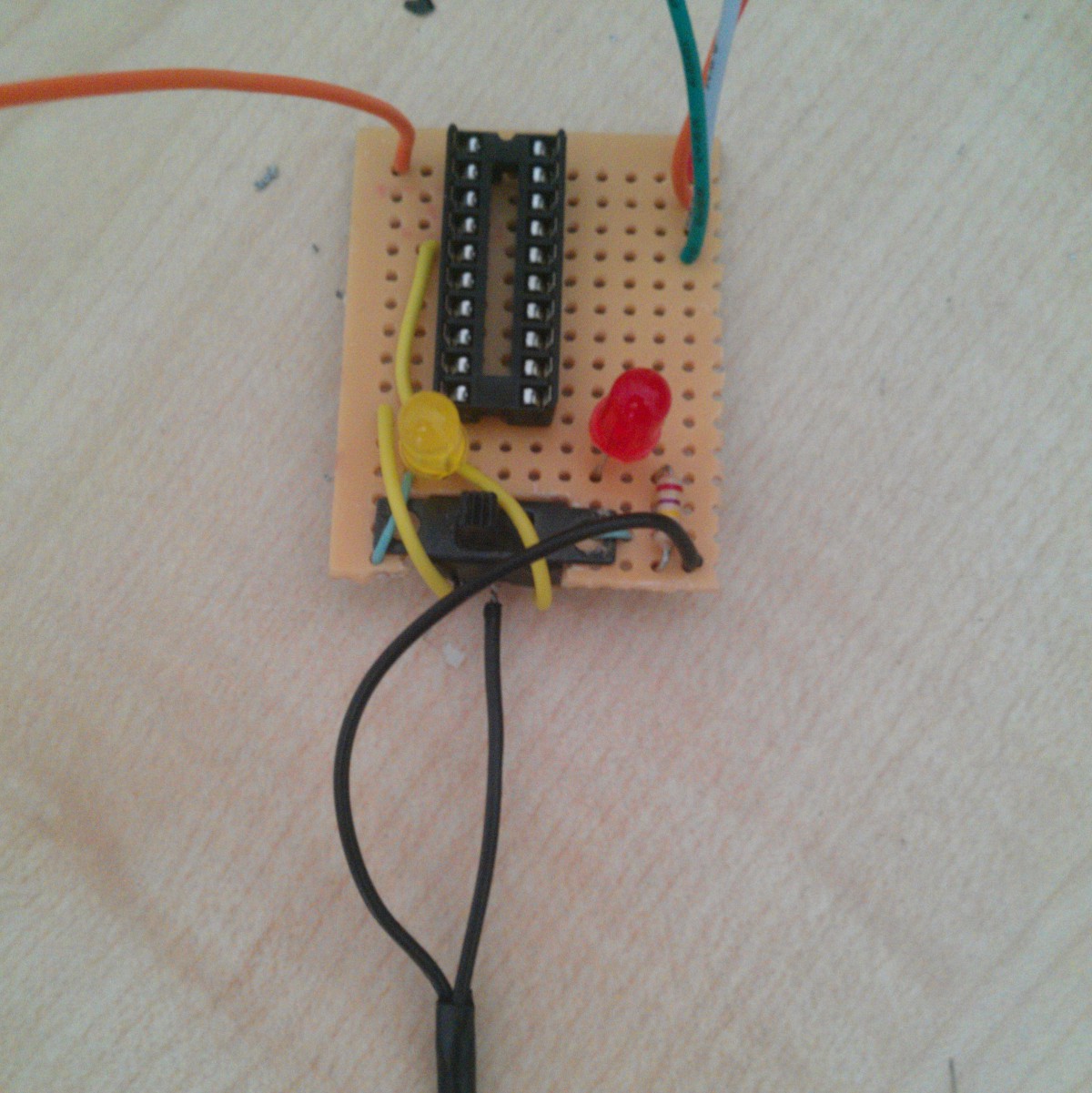
    Solder all the appropriate pins and components. Prepare the jumpers to be soldered next. I had to use the yellow leads since my switch wasn't exactly appropriate. I also had forgotten my LED jumpers at the stage of the photo.

  • 3
    Step 3

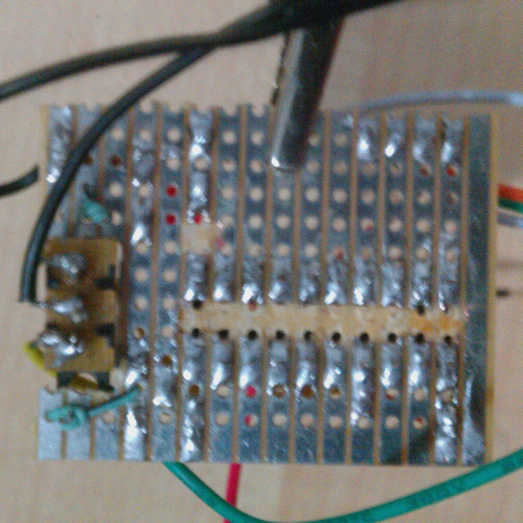
    Clean up the protoboard, remove excess board and connected rows that aren't meant to be. This can be easily done with side cutters and by heating the foil and scratching it with a craft knife respectively, if you don't have a Dremmel.

View all 7 instructions

Enjoy this project?

Share

Discussions

Similar Projects

Does this project spark your interest?

Become a member to follow this project and never miss any updates