-
1Step 1
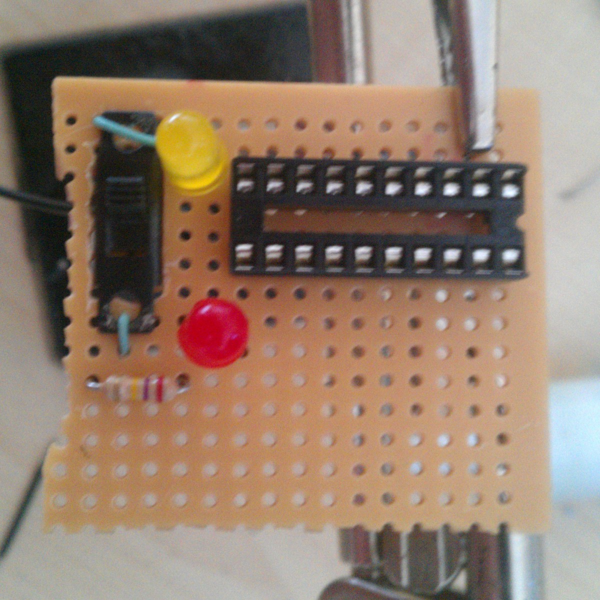
Add the resistor and LEDs, along with the socket mount to the protoboard for the first bit of soldering according to the circuit shown on the project Home Page. The green wires shown just support my switch (claimed from a broken Christmas hat).
![]()
-
2Step 2
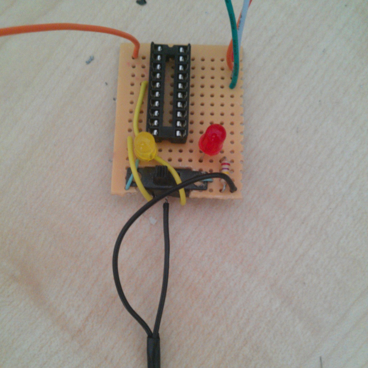
Solder all the appropriate pins and components. Prepare the jumpers to be soldered next. I had to use the yellow leads since my switch wasn't exactly appropriate. I also had forgotten my LED jumpers at the stage of the photo.
![]()
-
3Step 3
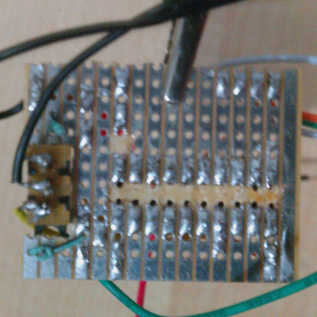
Clean up the protoboard, remove excess board and connected rows that aren't meant to be. This can be easily done with side cutters and by heating the foil and scratching it with a craft knife respectively, if you don't have a Dremmel.
![]()
-
4Step 4
Programming with the new device relies on a prepared ArduinoIDE set-up.
Download the IDE, I used apt-get for 64-Bit Ubuntu 14.04:
apt-get install arduino
Next you need the tools for ArduinoIDE to use an Arduino as an ISP (in-system programmer). Find that appropriate for your machine and set-up:https://code.google.com/p/arduino-tiny/
NOTE: V1.5 didn't seem to work at all for me but V1.0 worked perfectly. You can test your install by looking at Tools->Boards for the microcontrollers you added to your .../tiny/avr/boards.txt file.
-
5Step 5
Next you must prepare your Arduino as an ISP.
I used my Duemilanove but I think most Arduinos should work. I want to try my Hackaday.io Pro Trinket so that maybe I can make a all in one device :-)
To prepare the Arduino, upload the sketch to the Arduino via USB: File->Examples->ArduinoISP.ino
Verifying this upload is achieved in the next step.
-
6Step 6
Now connect your new "jumper plate" (it's not quite a shield) to the Arduino where A10 in the circuit drawing is port 10 on the Arduino, for example. The capacitor is intended on the Arduino between RESET and GND.
When the Arduino is connected, the red LED should pulse on and off. This is the AVR "heartbeat" verification.
To prepare ArduinoIDE to program your ATTiny, choose Tools->Programmer->Arduino as ISP and your appropriate ATTiny. Remember to select the right option on your device for the ground pin. Also remeber to change these settings when done to program your Arduino, itself, again.
-
7Step 7
To program the ATTiny now is simply a matter of uploading the appropriate sketch.
I made a Blink85.ino and Blink4313.ino to test my work. The results are shown on the Home Page of the project.
NOTE: Pins on the 4313 are a little obtuse, in my opinion, but I found the following cheat sheets where D8 for example is the integer 8 you use when declaring pins in Arduino IDE: Akafugu Reference Sheets .
ATTiny programming jumper plate with an Arduino
A simple board for programming ATTiny 2313/4313 and 45/85 microcontrollers using an Arduino and ArduinoIDE
 J3TTBlack88


Discussions
Become a Hackaday.io Member
Create an account to leave a comment. Already have an account? Log In.