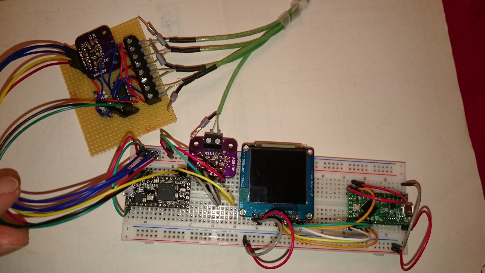
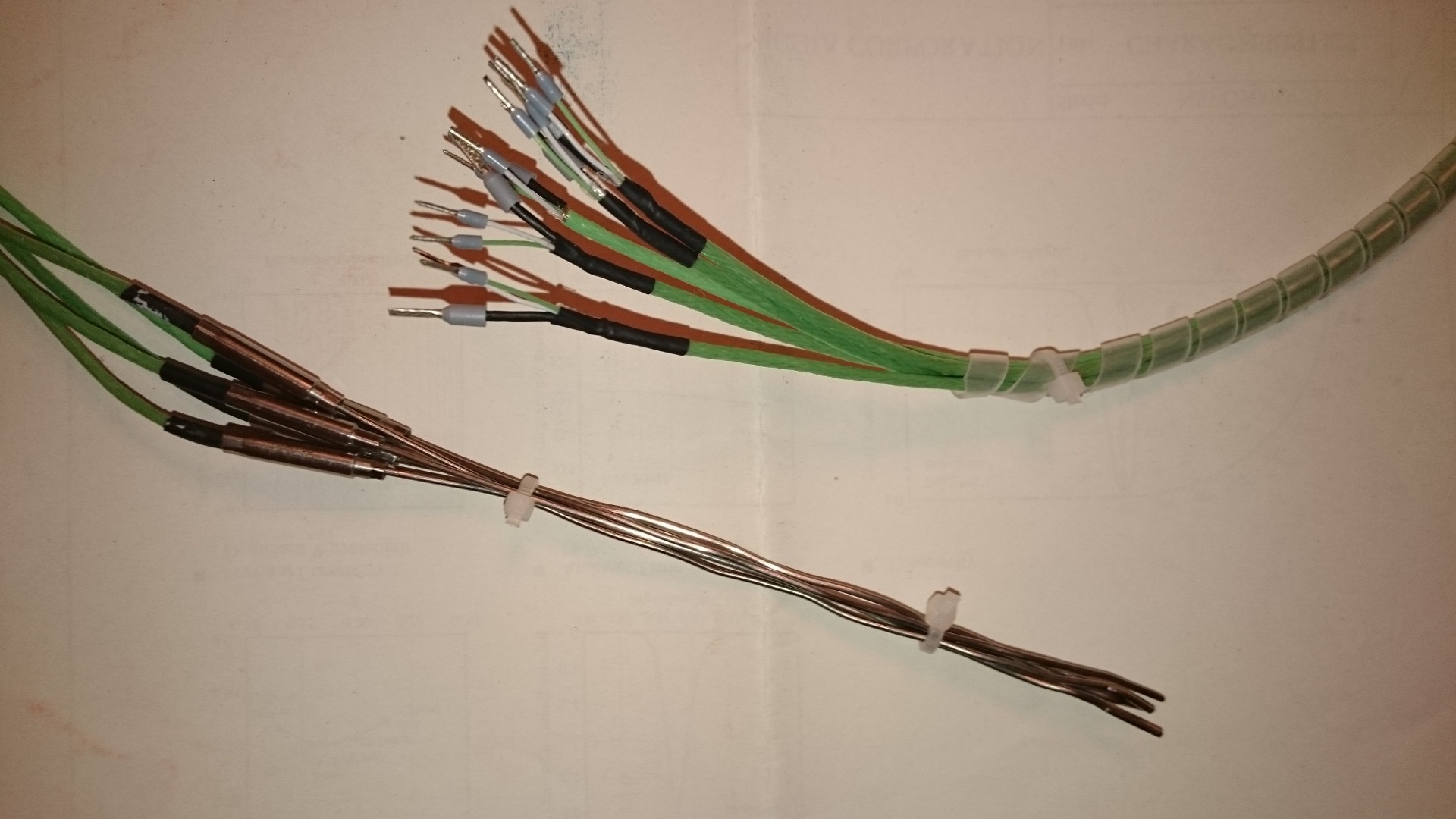
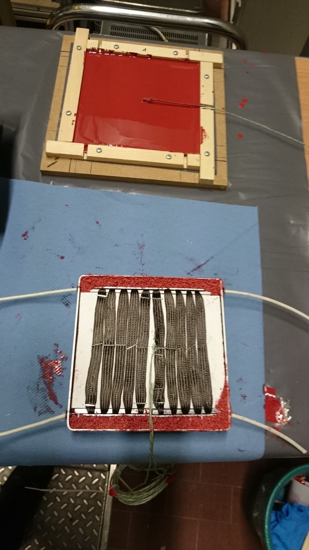
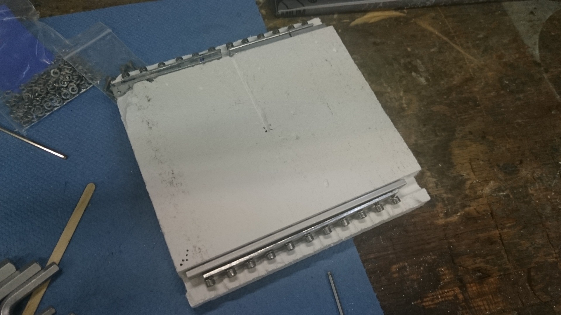
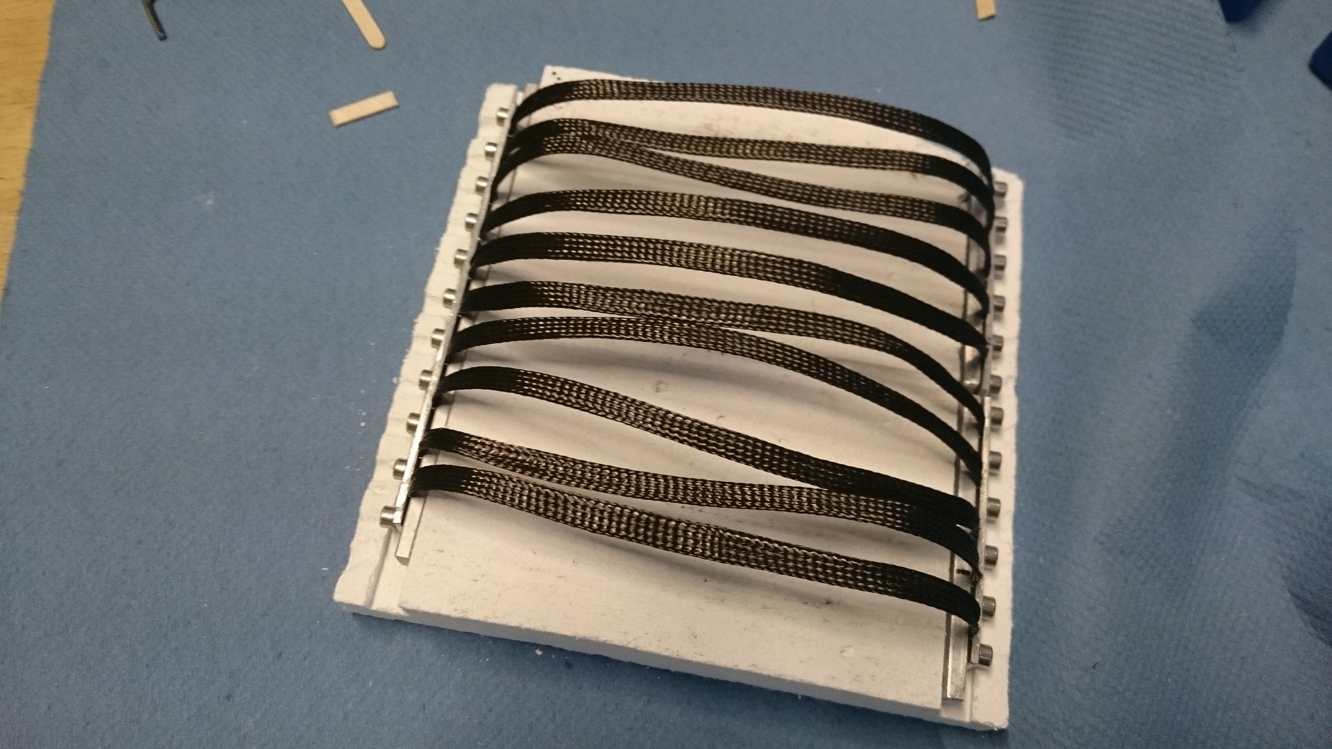
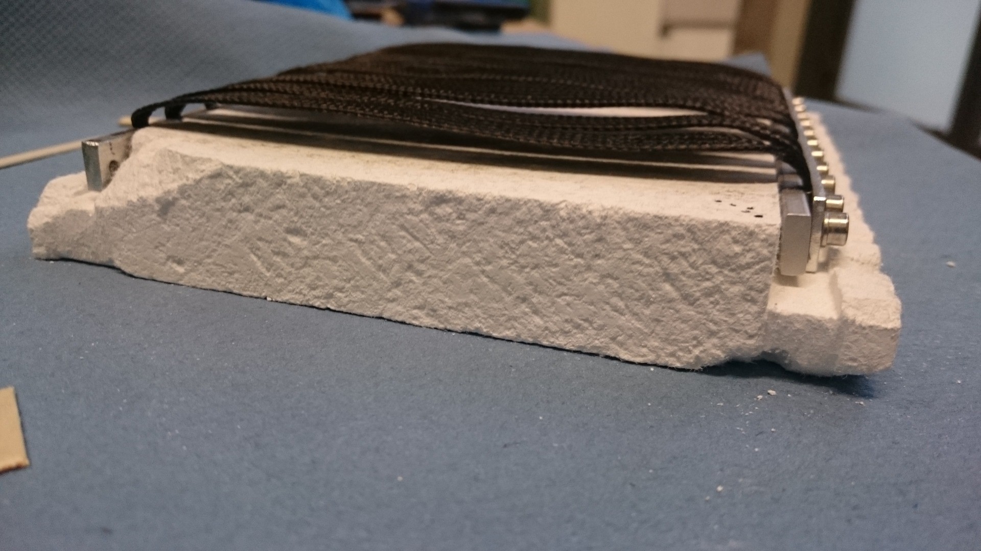
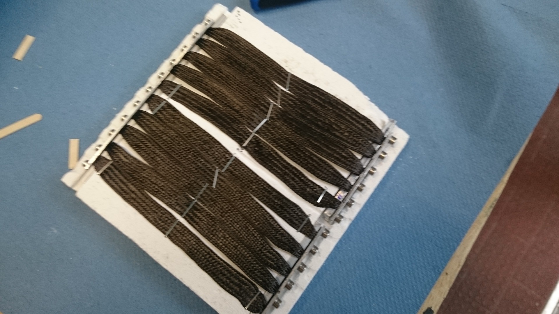
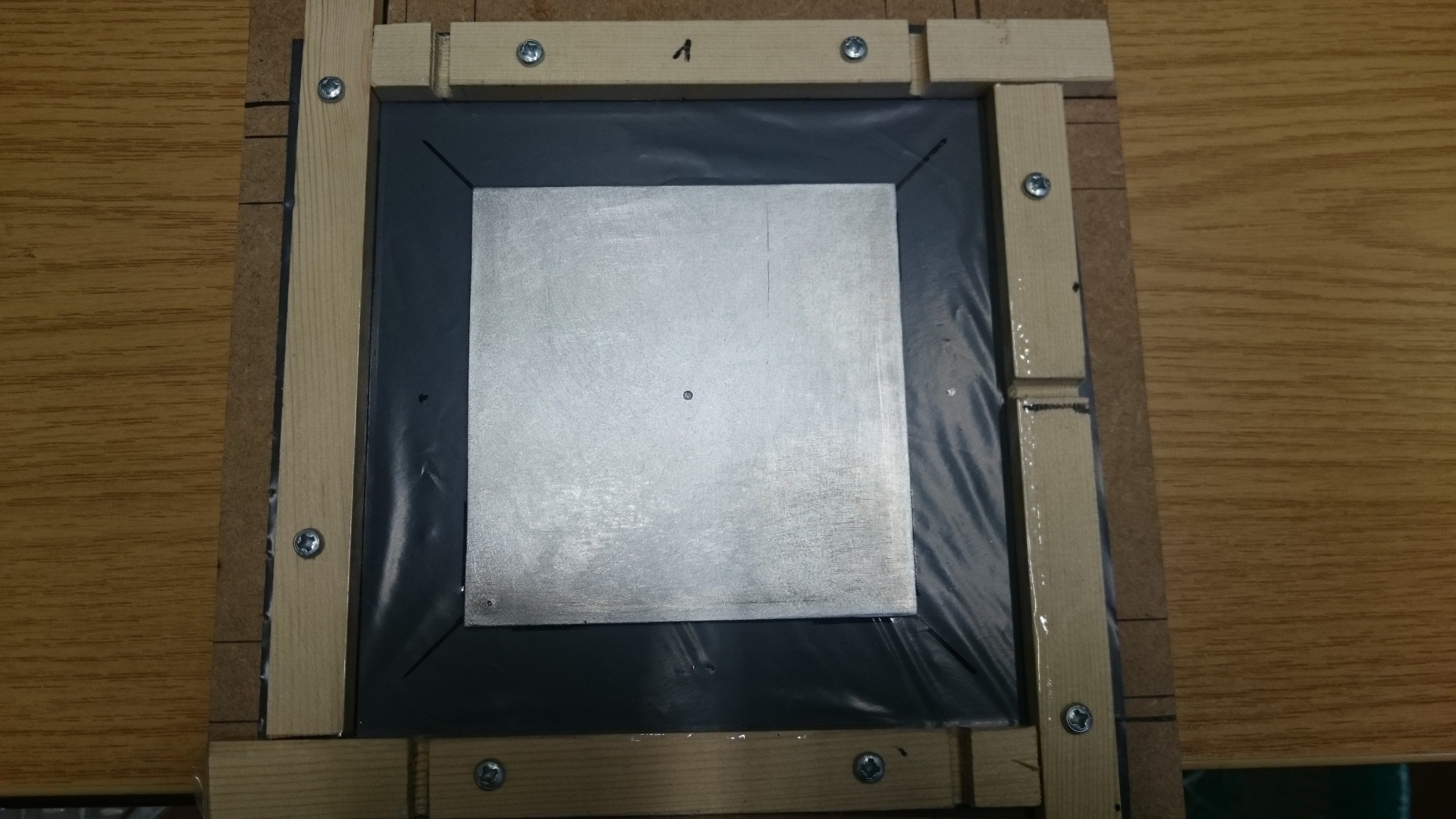
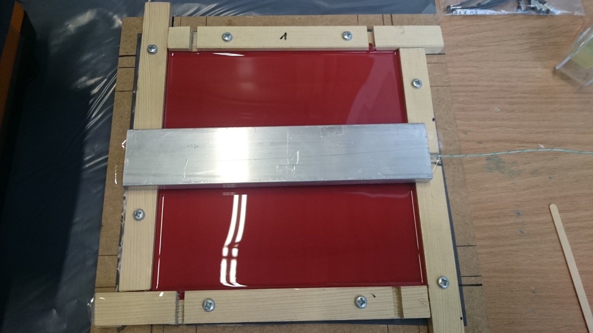
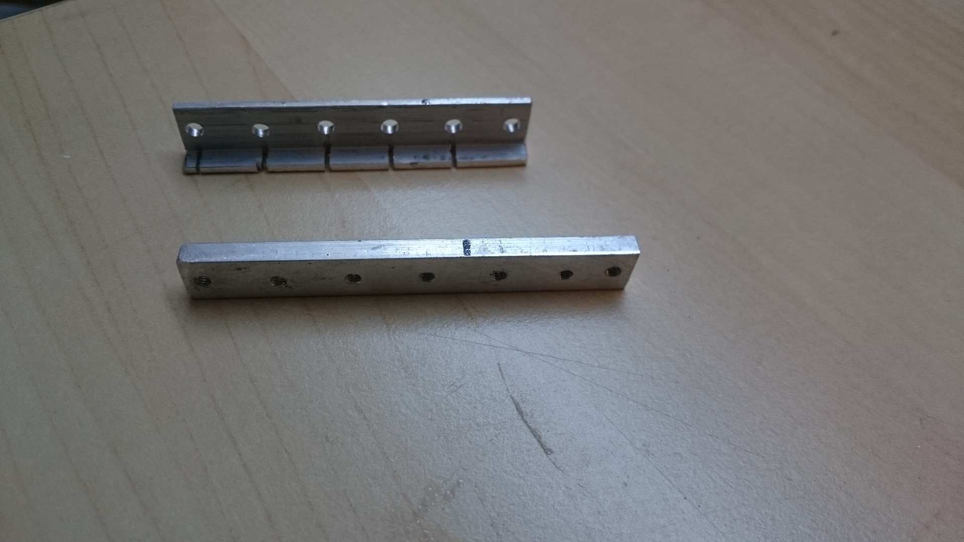
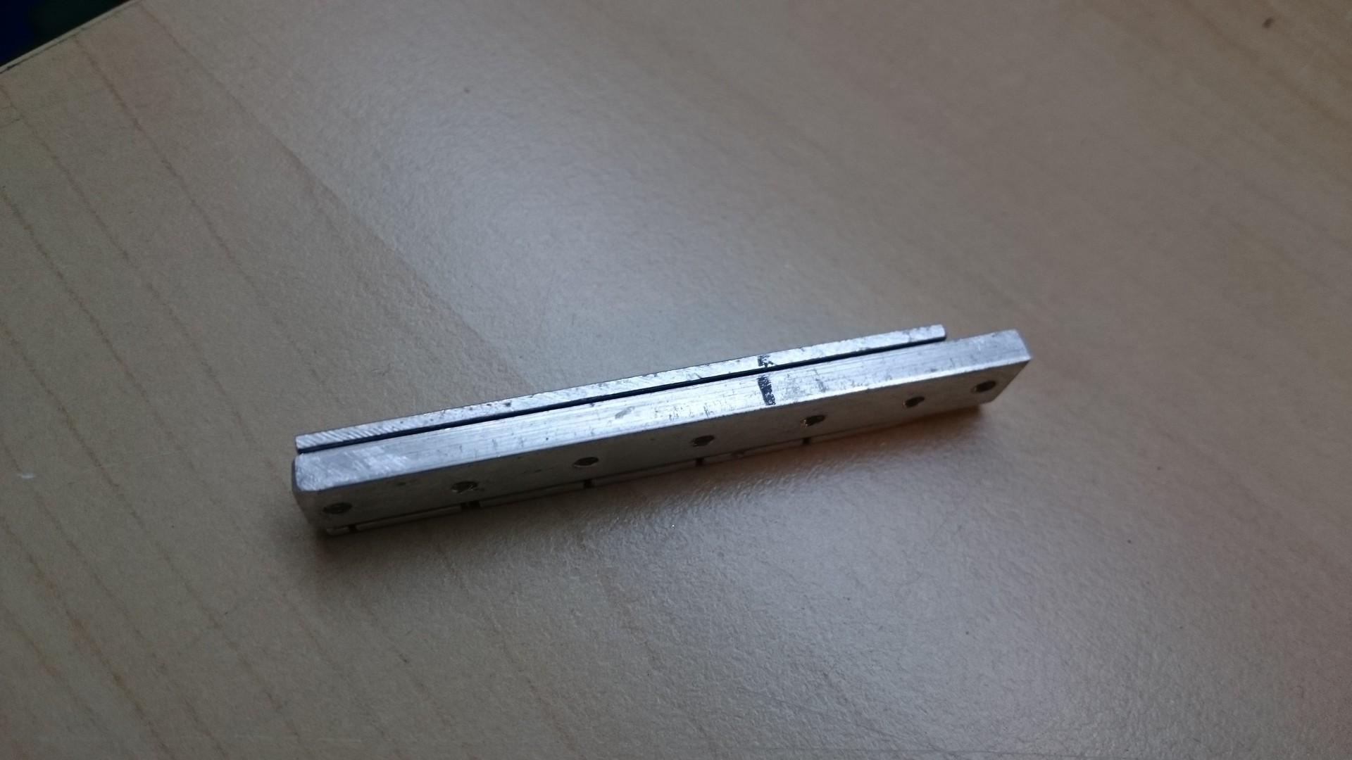
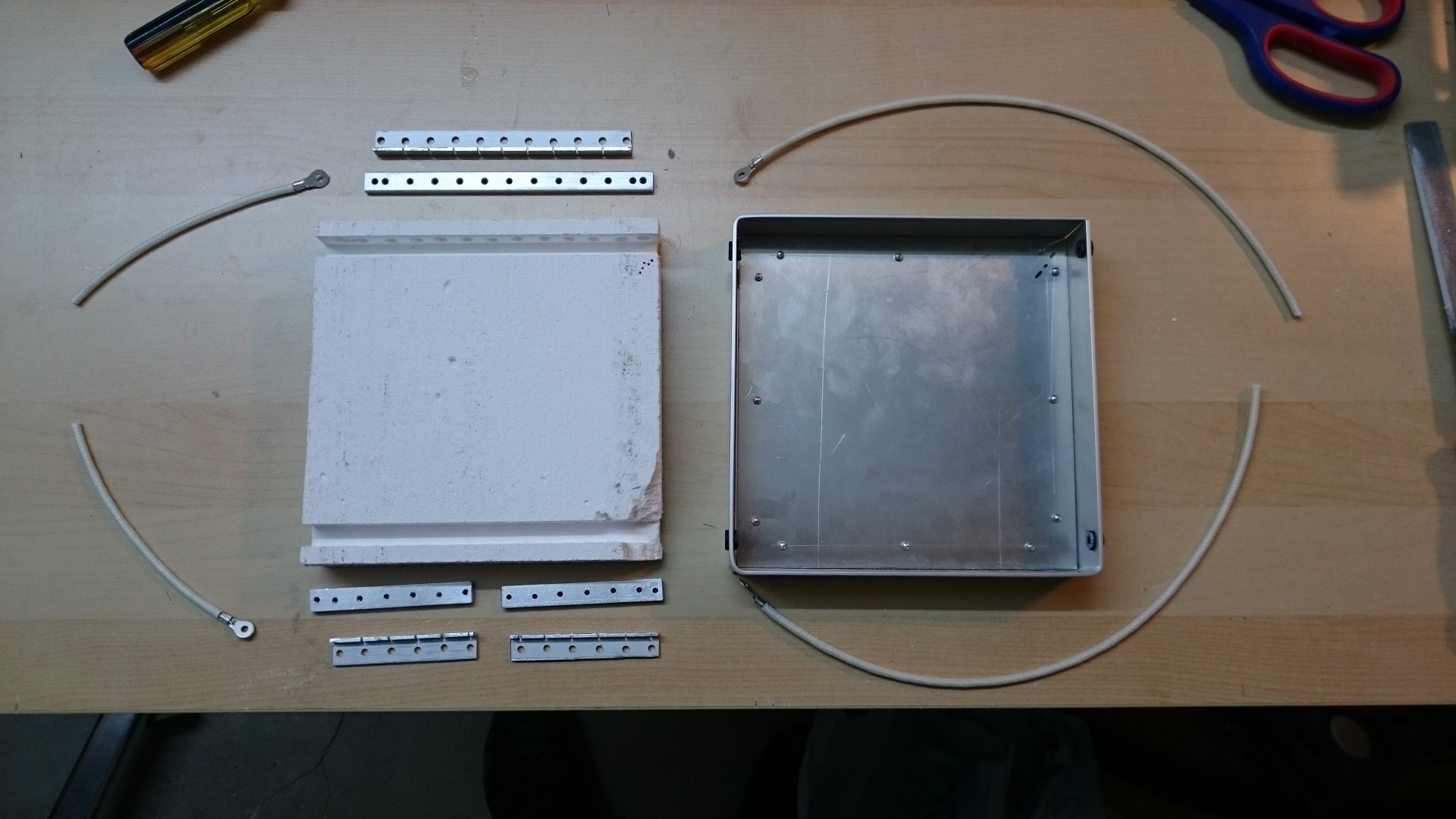
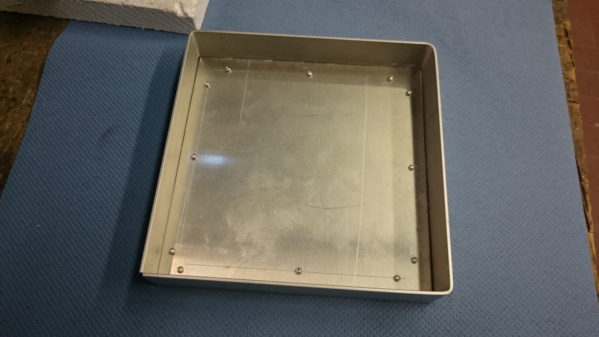
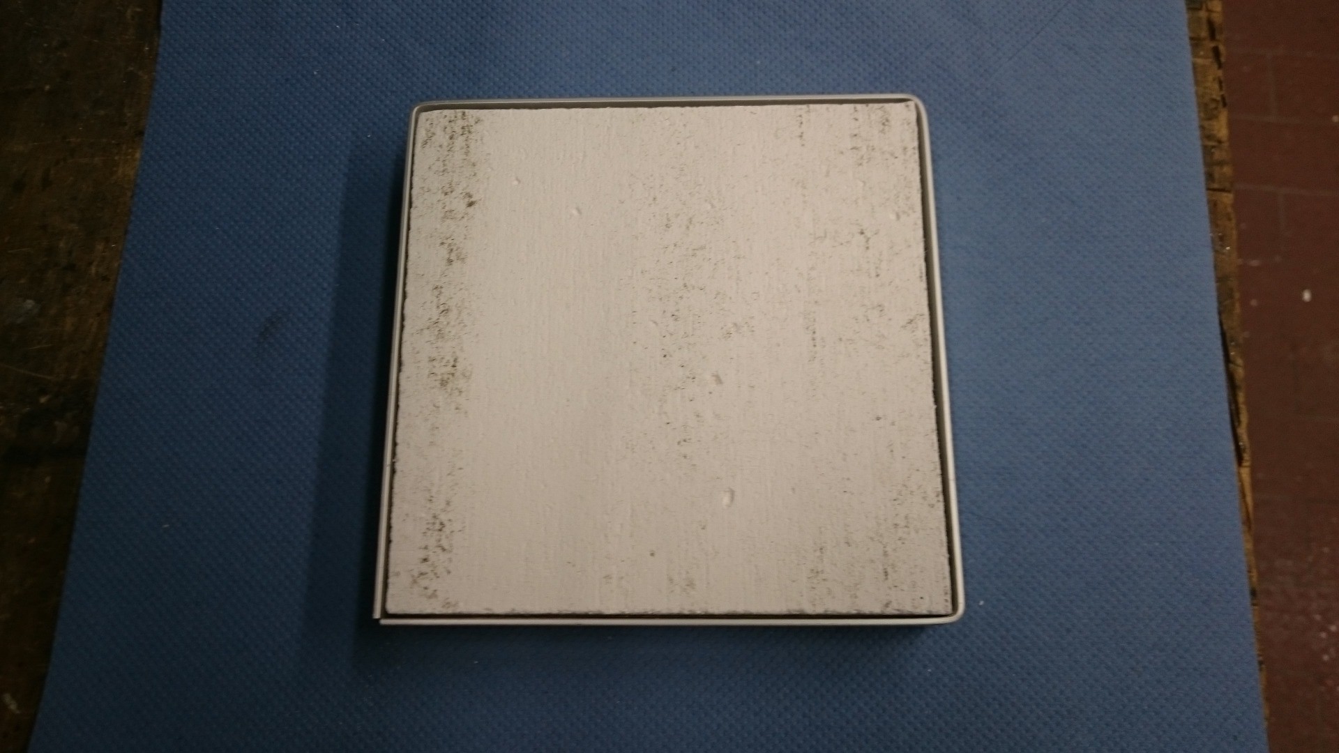
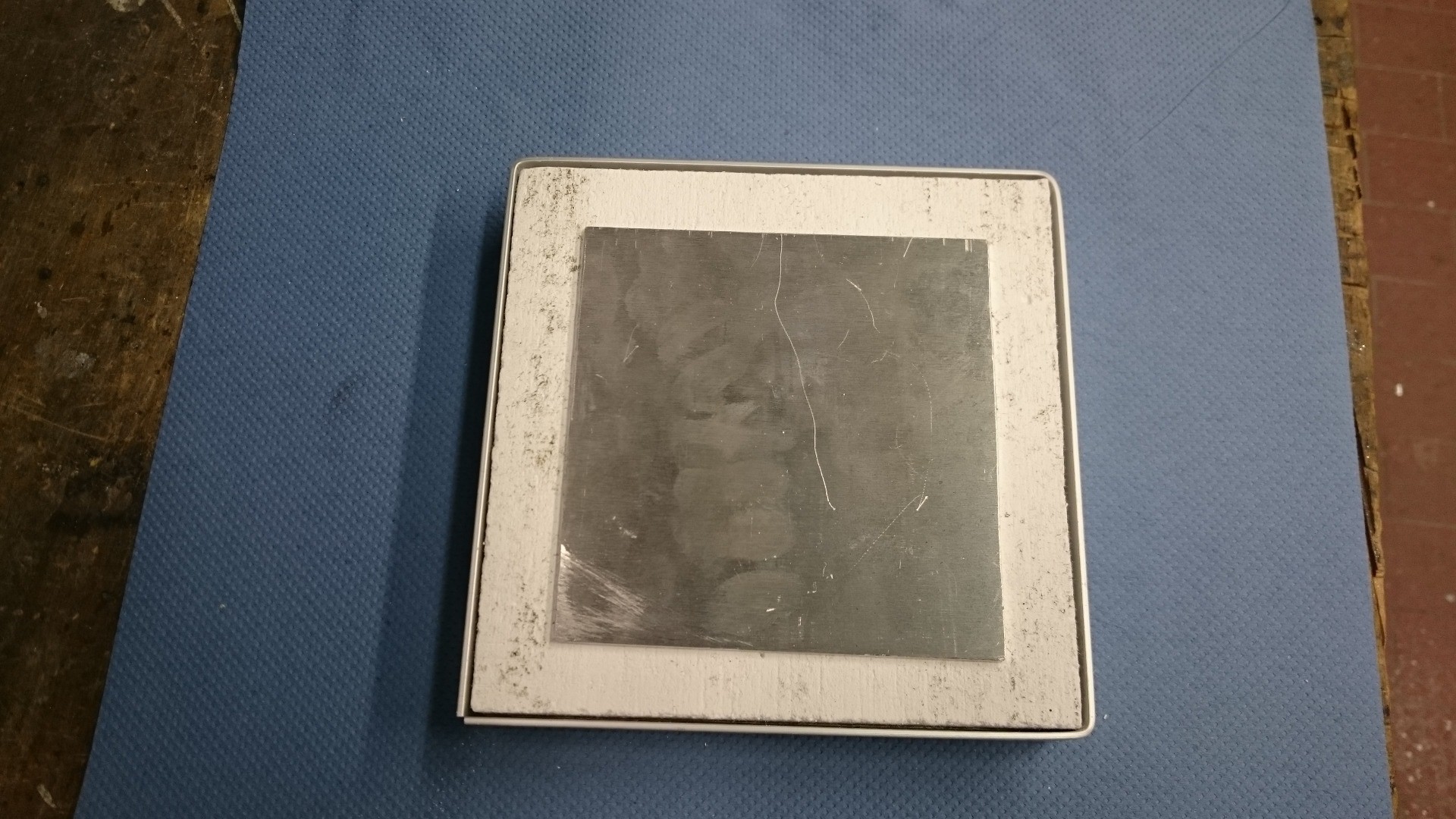
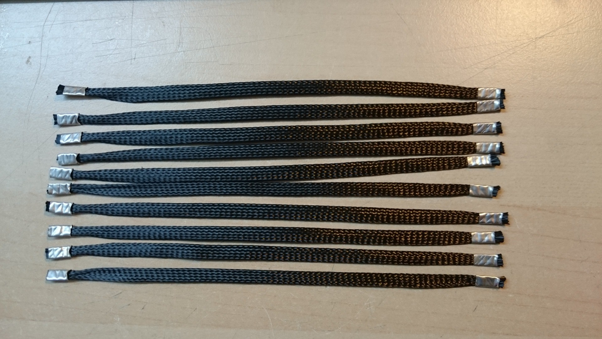
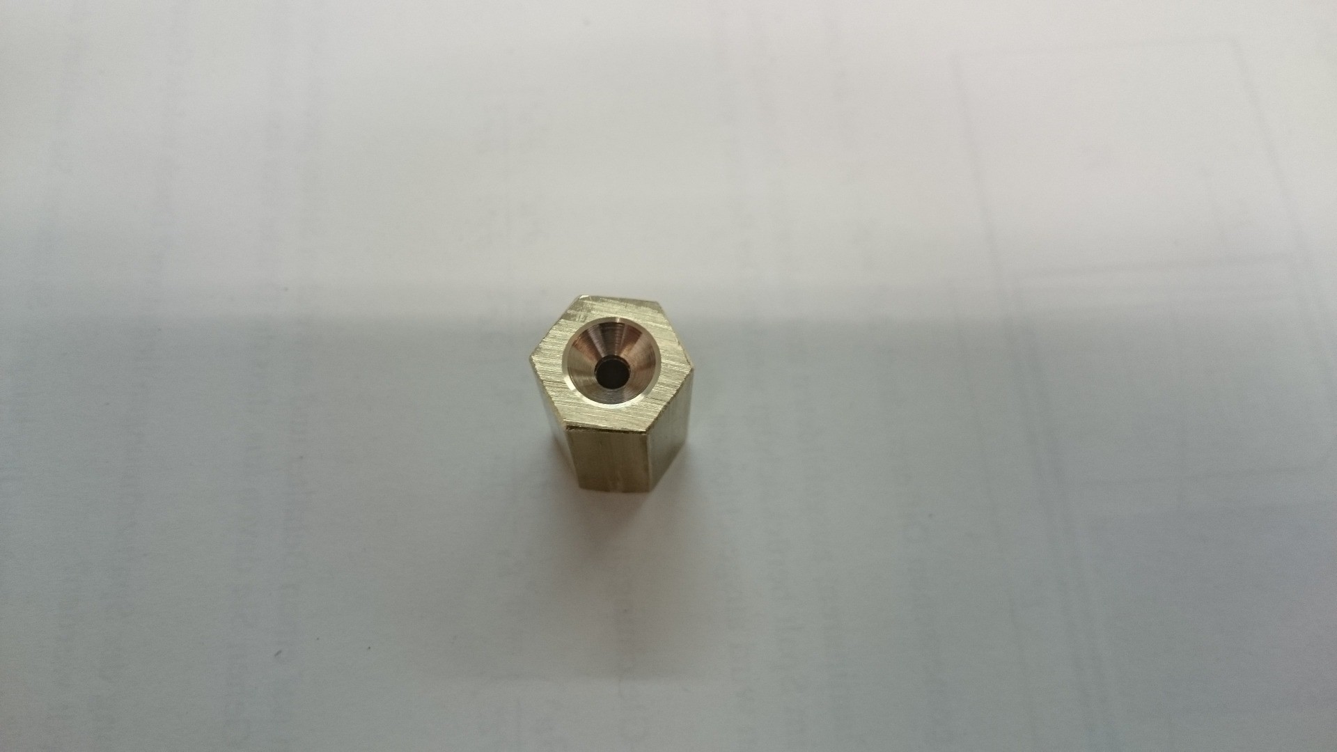
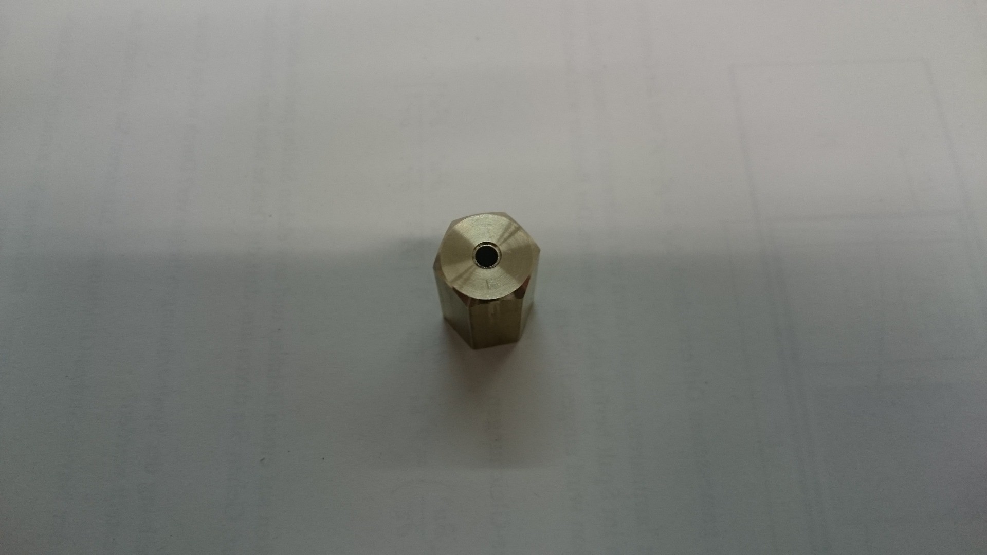
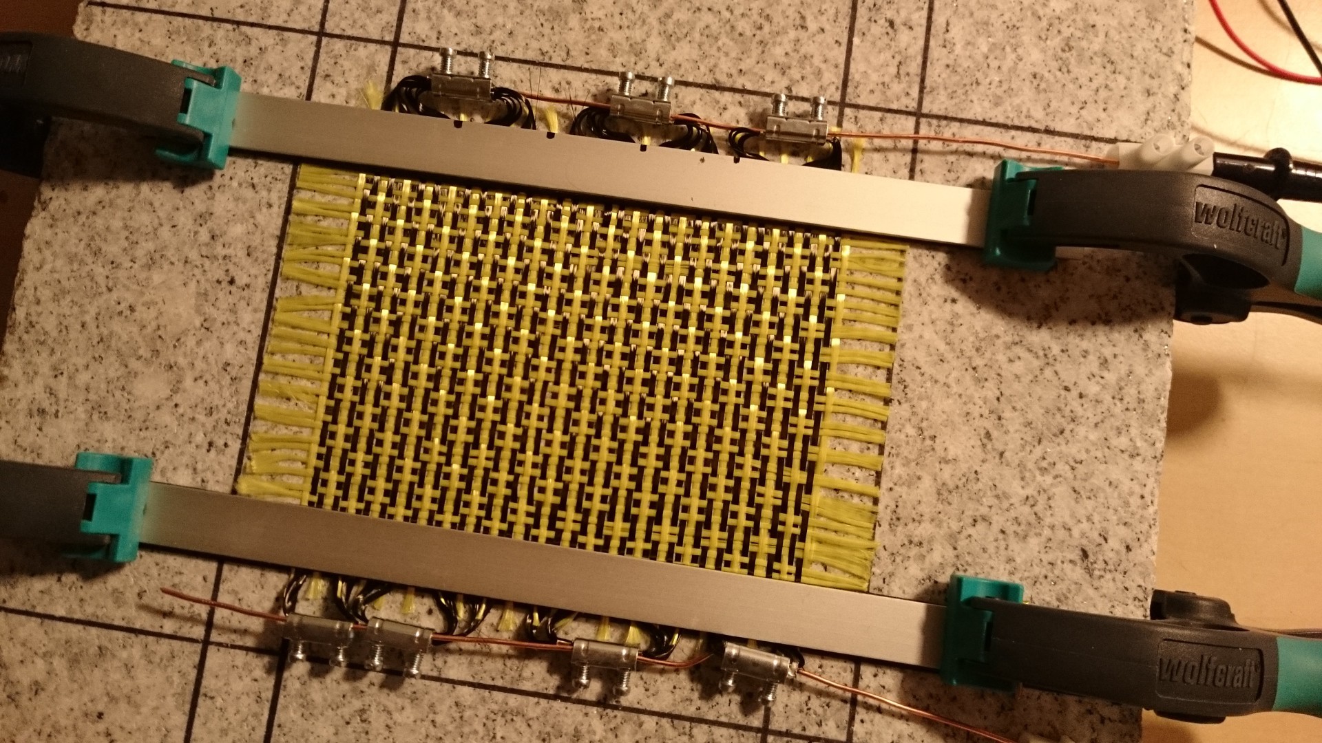
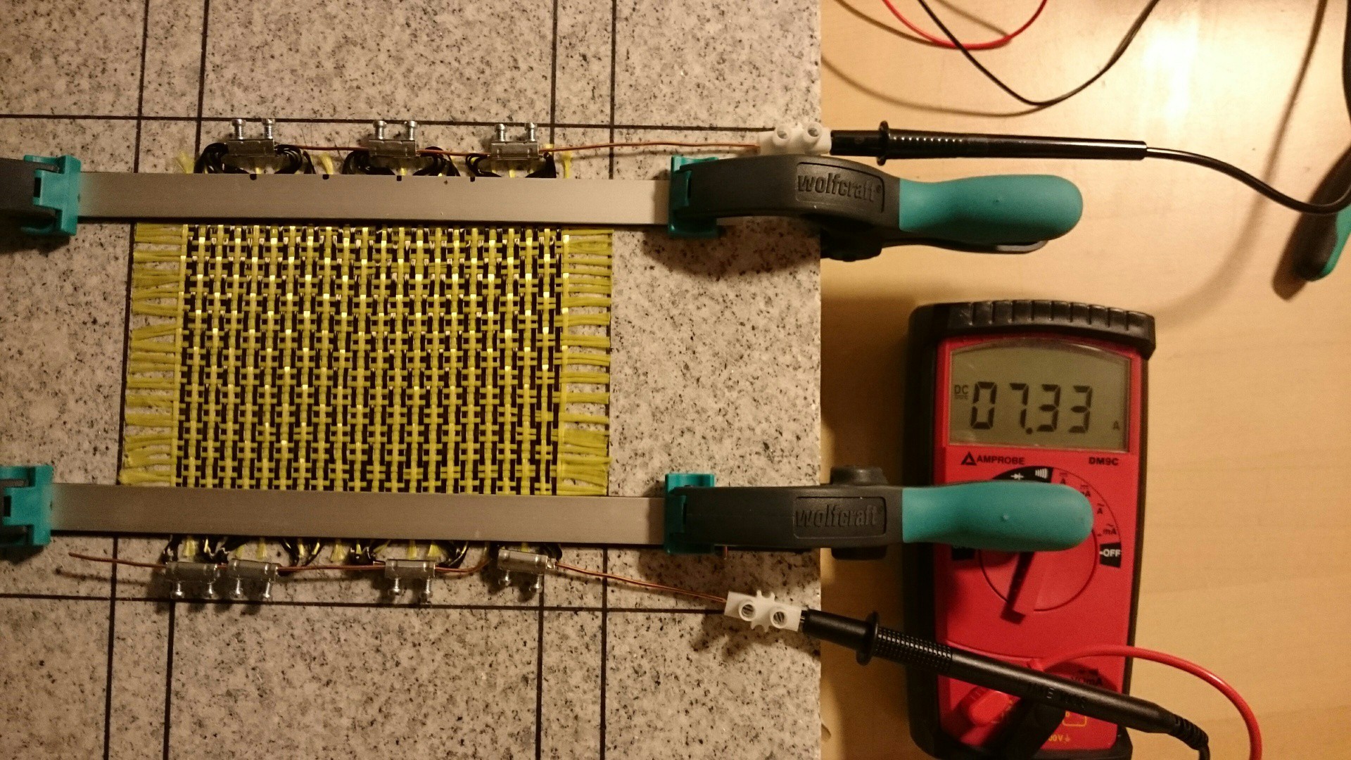
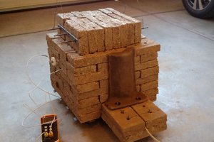
Because simply screwing or soldering resistors to a plate is boring.
To make the experience fit your profile, pick a username and tell us what interests you.
We found and based on your interests.
As it is now, the plate contains three K type thermocouples. Measuring temperatures with thermocouple requires appropriate amplification, and I like the AD8495 for that. I already have a breakout board for it (see my other project), but it's quite expensive - about € 4 for the less accurate A grade chip.
So I had a look at multiplexers. Various sources recommended one or the other device, some recommended against multiplexing at all. So I just gave it a go with the ADG409, which is a dual 4:1 multiplexer. Only one ADC channel and two digital outputs are needed for four thermocouples, which is really neat!
Here's a picture of my test circuit (ignore the display and the green PCB to the right)
It consists of
One thermocouple is used as a reference and directly connected to one of the AD8495s. The other four thermocouples are connected to the multiplexer, which enables one of them according to the address inputs.
Regarding cable end sleeves on thermocouple wires: I prefer not to crap my pants about this. They are part of the cold junction and A->B->C is just as fine as A->C is.
Long story short, here are the readings in tenths of a degree at room temperature and in steam above boiling water:
+------ first AD8495 v |<- second AD8495 ->| 218 224 222 222 224 1015 1027 1025 1023 1025The first column is the reference reading (no multiplexer) and the other four are multiplexed. Given that the AD8495A has an initial accuracy of max 3 °C I'd say that these are close enough to each other and to the reference reading - I'm quite satisfied with this result.
For 3.3V systems there's also the ADG1609 and probably a bunch of others. The green PCB in the first picture is the upcoming Teensy LC, which unfortunately is not 5V tolerant. The AD8495 outputs its positive supply voltage when no thermocouple is connected, or when the connection is broken, so that combo wouldn't have worked.
The result:
Measured resistance: 0.7 Ohms (series), so with a 12V supply it should dissipate about 200W.
Then I sandwiched the two parts and now I can't wait to see the result.
As I was inserting the clamps into their slots in the calcium silicate plate I noticed that the slots were a bit too narrow, and soon they broke away. So I cut them away completely:
The carbon tube resistors can be widened and shortened as intended, but they tend to go back to their original shape:
And they also don't stay flat on the plate:
A colleague then said "It's moments like these when you wish you could just staple them down". Brilliant! However brittle the calcium silicate may be, that makes it actually very easy to push in some staples (sorry for the crappy photo, but the idea comes across I think):
The top aluminium plate was placed in a mold
and covered with silicone:
I also added a glass silk insulated thermocouple for measuring the plate's temperature. The aluminium bar is just for fixing the wires in their place until the silicone has cured enough.
The next step (attaching the aluminium plate to the calcium silicate plate and the resistors) can be done when the silicone is hard enough, but still a bit sticky - otherwise it wouldn't be possible to add another layer of silicone to the existing one.
Slowly, things are coming together. I created long clamps that will connect the carbon tubes to each other and to their power supply:
combined:
Each resistor will end up between two screws. I have two of the clamps as shown above, and one long one:
Turned some more aluminium and rivets in to a bottom frame:
A calcium silicate plate (usually used for thermal insulation of fireplaces, for example) cut with a jigsaw, fits nicely:
This material can withstand very high temperatures (it was quite unimpressed by a blowtorch) and is very easy to cut and drill, but it's also a bit delicate and brittle.
Here's the aluminium plate that will end up on top of all that. It will be heated by the carbon resistors:
Using the brass nozzle makes the task of inserting carbon tube into a cable end sleeve easier by a felt order of magnitude:
The cool thing about the tube is that it has a variable diameter (or width when flat). Making it wider also makes it shorter, but its resistance doesn't change significantly. Then resistance per length can therefore be adjusted a bit, leaving some room for fine-tuning when I'm past the more-power-is-better stage.
Made ten of these in 20 minutes:
This "nozzle" kind of thing should help getting the carbon (in whatever form I end up using) into a cable end sleeve. Inlet:
Outlet:
First, some findings about rovings and ribbon tape:
So what's left? Carbon tube maybe. It's woven, contains nothing but carbon, and should be easier to handle than rovings. The diameter and per length resistance can even be adjusted a bit. I'll try that next.
Working with the single filaments in the fabric and clamping with those screw terminals was quite difficult:
So I'll also try to use plain (non-woven) rovings and ribbon tape and see if they are easier to handle. A simple tool for easier arrangement in the sleeve is probably also a good idea.
After connecting the other side of the fabric:
I could finally send some current through it. The measured resistance is about 0.6 Ohm ( a bit higher than calculated). With 5 V applied:
With 12 V applied it should have an output of about 212 Watt. I can now add a thermocouple, the aluminium plate and insulation.
(Edit: I forgot to mention that it does get warm - even though it's heating a large granite plate!)
Create an account to leave a comment. Already have an account? Log In.
Become a member to follow this project and never miss any updates