Close
0%
0%

12axis Flex Module

9-axis Gyro with the BME280 Pressure, Humidity, Temperature sensor

Similar projects worth following
Improved and lower cost position and environmental sensor Flex Module.

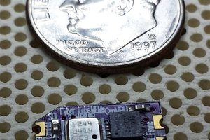
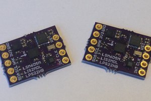
The 12axis Flex Module contains an LSM9DS1TR and BME280. The LSM9DS1TR is an accelerometer, gyroscope, and magnetometer or as commonly referred to as a 9-axis sensor. The BME280 provides barometric pressure, humidity, and temperature sensing. So I am calling it a 12axis Flex Module.

The board is configured for i2c communication. LSM9DS1TR has a separate address for the magnetometer from the accelerometer and gyro. The address least significant bit is selectable for those as well as the BME280. I have routed the first interrupt of the accelerometer/gyro as INTG and the magnetometer as INTM. The data enable pin of the accelerometer/gyro and the data ready pin of the magnetometer are also exposed.

Defaults addresses for the LSM9DS1 are as in datasheet and not common to most drivers based on the LSM9DS0. So adjust any examples from Adafruit, Sparkfun, etc. accordingly.

LSM9DS1:

  • Accelerometer/Gyro 0x6A (0x6B A.G solder bridge shorted)
  • Magneto 0x1C (0x1D A.M solder bridge shorted)


BME280

  • 0x76 (0x77 A.B solder bridge shorted)

Any software related will be released under BSD or MIT license. SAAS or cloud based software will be AGPL.

Creative Commons License

  • 1 × LSM9DS1TR
  • 1 × BME280

  • Fixing 2 layer pins

    Chris Hamilton08/31/2015 at 00:07 0 comments

    Somehow, I reversed the i2c pins on the 2 layer. So I will fix that before selling them. I still can't decide if the 2 layer or slightly smaller 4 layer design is better.

  • 2 layer success

    Chris Hamilton08/17/2015 at 17:03 0 comments

    We have found better performance in 2 layers, though the 4 layer boards do work OK. We might be able to determine the 4 layer issues, but I think it might come down to quality of solder mask. The 9 axis has some tiny pads, and for some reason the 4 layer quality just isn't there.

  • Still having problems

    Chris Hamilton07/19/2015 at 09:38 0 comments

    I think having 4 layers has complicated things. I am having serious issues communicating with the chips. So I am reducing the layers, spreading the chips further apart, and minimizing the amount of traces under the components. I hope to see a serious improvement.

  • Update Solder Bridges/i2c

    Chris Hamilton02/18/2015 at 17:20 0 comments

    Increasing size for easy hand soldering. Rearranged i2c bus similar to other Flex Module designs.

  • Quick design

    Chris Hamilton02/12/2015 at 00:09 0 comments

    Similar to the original 10-axis design. I have already sent the boards to be made by OSHPark.

View all 5 project logs

Enjoy this project?

Share

Discussions

Rob wrote 11/18/2019 at 13:50 point

I love this project, so many applications. :) It fits the bill for a fun project I'm looking at for leveling machines. 

  Are you sure? yes | no

Julian Blanco wrote 05/06/2016 at 06:47 point

Are you attaching all the components by hand? If so how?

  Are you sure? yes | no

Chris Hamilton wrote 05/06/2016 at 07:56 point

I have some old write ups on my old tumblr blog, but they are not the best - http://blog.ambiguous.net/.  The quick answer is paste stencils from oshstencils.com,
paste from chipquik (we like SMD291) or any other electronic solder
paste (not flux), esd tweezers and patience, and a hot air solder
station or small Chinese reflow oven.  Hope that helps.

  Are you sure? yes | no

Similar Projects

Does this project spark your interest?

Become a member to follow this project and never miss any updates