Close
0%
0%

Cheap n' Nasty Cutting Machine

Yet Another CNC Machine

Similar projects worth following
Aim to build a CNC machine that can handle cutting/milling aluminium. Limited by available space, money, time etc.

I've been planning a CNC build for years now, but finally I'm in a position to make it a reality.

A lot of design ideas have been considered, but ultimately the final choice is down to available materials, tools and space.

I've split the design into three major areas: frame, power transmission and control electronics. The current design is based on a welded steel frame, SBR16 linear slides and threaded rod for movement, and TB6600 stepper drivers being commanded from GRBL.

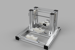
I'm hoping to start welding up the frame this afternoon. The attached rendering is a very rough plan of what the machine will look like – so far the only accurate part of the model is the frame dimensions. Other parts have either been simplified or omitted at this stage. I'm going for a very modular build, where components can be changed out or upgraded as funds permit. So although my initial build is going to use stainless steel threaded rod, later on I'll upgrade this to ACME rod with a proper ball screw.

So here it is: The Cheap n' Nasty Cutting Machine.

I've done some very basic finite element analyses on the steel box section and found that deflections should be within acceptable ranges -with a 30kg load and a 3Nm torque on the bottom frame, the maximum deflection is 0.03mm with the frame only supported at each end. The frame will have more supports than that (at least 3 feet per edge), and the total loading shouldn't be anywhere near 30kg!. Swiching to Aluminium would increase that deflection by a factor of 3.

Once concern is the mass of the gantry. Making the gantry from steel means there's a fair old bit of weight for the X axis stepper motor to shift. Fag packet calculations put the the steel gantry, without Z axis or cutter head, at 6.7kg. I might use aluminium section for the gantry (2.4kg), further thought required here though as an aluminium gantry would have to be bolted together (yay, adjustable for squareness!) and less rigid than a welded solution (boo, less capable of keeping its squareness).

FEA results: https://www.youtube.com/watch?v=7q1q4ejgPcE&feature=youtu.be

  • Tb6600 Drivers

    koswix03/11/2015 at 13:46 3 comments

    2015-03-10 19.04.57Not much to report at present, real life has been getting in the way again. But the stepper drivers I ordered from China have finally turned up, and I had a chance last night to play with them.

    So against all the advice found online, I ordered some TB6600 based drivers from eBay. At the price (£11 per axis) I figured it was worth a punt, as even if they're pap I can sell them back on eBay and at least recoup the cost…

    First thing to note is that these PCBs appear to have a different layout compared to the ones I've seen discussed on CNC forums. I hoped that it was a newer, better design. The other boards I've seen have all the inputs and outputs along one edge of the board, these ones have the step input control on one side, and motor and power supply on the other.

    They're supplied with 4 brass stand-offs, and a heatsink on the TB6600 chip. Immediately I noticed a problem here: the heatsinks are mounted on the *bottom* of the chips. I know I only scraped through my Thermodynamics class last semester, but I'm pretty sure having the heatsink on top of the chip would be a squillion times better. I plan on replacing the heatsinks with something bigger anyway, either with directly mounted fans or in an air cooled box with the other electronics.I suppose I could even leave the underside coolers on and just add a better cooler to the top side.

    Surprisingly for boards from China, these things also came with a data-sheet of sorts, detailing the various limits for inputs/outputs, wiring examples and DIP switch settings. Foolishly, I believed the datasheet and wasted 30 or 40 minutes trying to get the board to respond: the Enable PIN has to be pulled LOW to enable the board, not HIGH as stated on the sheet!

    I hooked up the board to one of my steppers, a 30V, 3.5A bench supply and an ARM mbed micocontroller to provide the clicks. My code for the mbed was very rudimentary, all it does is send the ENABLE pin LOW (haha, eventually), Direction pin HIGH and provide a pulse to the step pin every 0.4 Seconds. I thought it best to keep it simple to start with (code used is at end of post).2015-03-10 19.04.47

    I grounded all the -ve pins on the input side together and to the mbed, as shown in the data sheet diagram. The input side is opto-isolated so the inputs must be grounded separately to the motor supply.

    Plugged everything in, checked all the connections, turned it on and… nothing. Well, almost nothing. The motor is trying to step, but is just wiggling back and forward. I know the motors work (see previous posts for test), and the TB6600 board is responding to the pulse (the LED on the TB6600 board flashes for each STEP command it receives), but I just can't get the thing to move. I tried a whole bunch of different timings for the stepping, including a 50% duty cycle between STEP and NOSTEP, but nothing worked. The closest I got to making it work was manually touching the STEP wire to a 3.3V source. If I 'vibrated' the wire just right off the 3.3V output pin on the mbed I could more or less get the drive to rotate.

    I'm a bit stumped now, one of my lecturers and a few other students helped out probing the thing with a scope, and even triggering the scope from the step pulse, but we couldn't really make head-nor-tail of the output. The coils were definitely bouncing between 0v and +10v (the bench supply was set to 10v at that point), but not actually rotating.

    Also tried one of the other boards and one of the other motors, all with the same result.
    So what am I doing wrong? Is it a grounding issue? I've had odd behavior with steppers before when there was a grounding issue between the driver and the MCU, but that didn't seem to solve the issue this time. Any advice gratefully received!

    Video of the motor failing to rotate:

    Code used on the mbed:

    #include "mbed.h"
    Serial pc(USBTX, USBRX);
    // used to communicate with a terminal on a PC – not actually implemented here so can be removed
    // Planned to have RPM and direction selectable via terminal, but sadly never got that far!
    DigitalOut...
    Read more »

  • Motors Arrived!

    koswix02/23/2015 at 21:52 0 comments

    I order some steppers from CNC4You on eBay on Friday, and they turned up today with DPD (actually it was early: DPD text you a 1 hour time slot in the morning. The guy turned up a minute before the earliest time allowed and we had to stand their awkwardly making small talk until his scanner would let me sign for the package :'D ).

    I don't have the proper drivers yet, but I was desperate to check that they worked and see what they were like. I hooked them up to an EasyDriver board and turned the current pot up to the heady max of 750mA. Coupled with the world's simplest Arduino stepper sketch, I had working motors!

    I'm really impressed with these so far. They weigh just under 1.5kg each, and even being driven with 750mA @12V they produce useful torque. I was totally unable to stall them by hand. This looks quite promising for my machine!

  • Welding!

    koswix02/19/2015 at 21:43 2 comments

    2015-02-19 16.44.08

    So I had my first proper welding lesson today, so much fun! Keeping in mind that I had about an hours practice (taking it in
    turns between 4 of us) I don't think I did too terrible a job welding the frame together. It's not pretty, but it seems rigid and the frame is pretty damn square so I'm happy with it. I'll grind down the welds next week to make a nice smooth surface or mounting the rails to. I've welded up the bottom frame, and two feet/legs for the gantry. Very satisfying work, and I was really getting the hang of it by the end.

    2015-02-19 15.42.15Also been thinking more about the toolchain I want to use with this thing. Some of the features of LinuxCNC are very tempting – particularly the addons that allow proper use of a height probe. I'm just not convinced by hav2015-02-19 15.42.28ing to use a desktop PC with a parallel port to control it all. Putting a force air cooled PC in a milling environment just doesn't seem that sensible, although I am considering a sound-reducing enclosure for the mill so we'll see. I think I'm going to push ahead with GRBL to start with, and move over to LinuxCNC once I've enclosed the mill.

    2015-02-19 16.44.222015-02-19 15.42.15

  • Some progress, frame coming on

    koswix02/18/2015 at 21:14 0 comments

    o I had to make some changes to the frame design. Not because of any design problems, but because there was a bunch of steel section in the scrap bin that was looking for a home.

    Overall the new frame dimensionally the same as before, but now constructed from 25x25mm box. As the SBR16 rails have a 40mm mounting plate, I'm going to run two legnths of 25mm box along two sides.

    The steel is all cut to size(ish, must learn to use saw2015-02-17 15.17.43s better…) and ready to be welded. Was hoping to get that done today, but ran out of time. I've never welded anything before, so I did get a chance to do some practice welds today and it went pretty well!

    I've also cut two 600mm lengths for the grantry, and made two feet out of 50x25mm section (the only bit of it lying around I could steel). I've drilled the holes for mounting to the SBR16UU bearing blocks, and I'll weld the legs onto the feet when I do the rest of the frame.

    2015-02-18 16.08.30Current thinking is to use a bolt-on system for the gantry, so that it can be adjusted for squareness once all the other bits are in place. Not sure if this is a good idea or not yet.
    Motors:

    Been looking at these bad boys and after some comments from a lovely chap called Kert (and not Ken as I original misread his name as!) over on Hackaday.io I reckon the mass of the gantry isn't going to be too much of a worry.

    Drivers:
    A bit stuck here. I love the price of the TB6600 drivers on ebay (around £11 per axis), but getting not so encouraging reports on their quality. There seems to be a few different board designs, though, so hopefully some more research will reveal one of them that works as advertised :D

    The next option I've found is about 3x the price, using the CW4056 (or something like that) drivers. More thought/research needed.

    Summary:

    Slower progress than I'd hoped, but still progress.

  • Bottom frame progress

    koswix02/17/2015 at 21:14 0 comments

    Slight change in the design of the bottom frame - was offered some 25x25mm box section for free so decided to go with that. I'll weld two lengths together along the rail sides so that there's enough room to mount the sbr rails.

    The lengths are all cut to size, just need to clean up the ends and weld it together tomorrow.

    http://m.imgur.com/qGW5ddp

View all 5 project logs

Enjoy this project?

Share

Discussions

georgefomitchef wrote 02/12/2016 at 08:56 point

MakeBlock XY plotter kit transformation


MakeBlock XY plotter is really good thing to use for engraving and laser cutting because

it has bigger sizes comparing to DIY kit. 31 X 39 cm (is quite a lot)


As far as we know there is a laser kit for MakeBlock but we did not try it. If anyone has
an experience, please share with us!

  Are you sure? yes | no

koswix wrote 02/17/2015 at 21:09 point

Hi Kert, thanks for your comments. Some good reading there on the TB6600. I have had a quick look at the data sheet for the Toshiba chip and it certainly ticks the boxes on paper - I wonder how many of the problems with these boards are either bad board design (likely) , or perhaps even counterfeit chips (less likely, maybe). 

I'm aiming for something around 3 N.m steppers, so I suspect that I'm going to have to find a high current driver to pull that off. Heat is always going to be an issue with high currents in an IC, so perhaps discrete components might be the answer. I'm a mechanical engineer (well, student *grin*) so sadly the electronics are not my strong point. I do know a friendly electronics lecturer though so no doubt I'll be picking his brains soon! 

I think the sbr16 stuff is rated around 700 N but will definitely double check before I order. 

  Are you sure? yes | no

Kert wrote 02/18/2015 at 07:11 point

As far as I understood the problems highlighted in that forum thread rise from bad board design decisions, not from the chip itself. The chip itself should be pretty ok if used as suggested in the datasheet. If you do your own PCB's they should be ok. 

3 N.m is quite a lot of torque at 10mm metric leadscrew. If used for z-axis, for example it should be enough to rise 200 kg load assuming 0.25 friction coefficient according to this online calculator: http://www.daycounter.com/Calculators/Lead-Screw-Force-Torque-Calculator.phtml

For x and y axis it should be capable of dragging around more than that. Then again stepper torque drops off once you get to higher rpm. 

  Are you sure? yes | no

koswix wrote 02/18/2015 at 09:57 point

I may have overestimated my requirements there, then! Might have to make the frame strong enough to stand on and have the machine move me around :D

(although big caveats with those calculations, the Cf is notoriously hard to estimate and the only reliable way to calculate the (linear) force from a screw torque is to measure the deformation with a strain gauge)

Also as you rightly note, as RPM increases, torque decreases. Similarly as micro-stepping is introduced, the torque goes down. Add on to that that a cheap, eBay 3Nm motor is very unlikely to actually achieve anything like that... I'm banking on having to overestimatethe spec on these things to get something useable. 

  Are you sure? yes | no

Kert wrote 02/17/2015 at 19:20 point

I would steer clear of TB6600 - there is good discussion on these in http://www.cnc-arena.com/en/forum/tb6600-drive-ebay--186930-11.html (I am Carniflex in that thread asking about how good these are on page 11). Go instead with DRV8825 based board. It's a bit cheaper, lower max amperage, unfortunately, but also is said to be pretty good as long as you stay under the max allowed ampers (voltage and preferably drop a extra heatsink on it. 

Ofc - if the stepper you intend to use needs more ampers than comes out of DRV8825 it might not be suitable, but then again as far as I understand you have not yet decided on the exact stepper motors. 

Also, take note of the allowed loads for the 16mm semi open linear bearings. I'm not sure from top of my head and it probably should not be a problem as I have a vague memory of seeing some pretty good number (perhaps 770N?) for these but it might be worth cheking the number out beforehand just in case. 

  Are you sure? yes | no

Similar Projects

Does this project spark your interest?

Become a member to follow this project and never miss any updates