-
1Design and Modeling
The first step to creating any new piece of hardware will naturally be the conceptual design and 3D modeling of the part. For some software suites it will be ideal to first model the part you wish to create, and then use that model to define the geometry of the inner and outer mold pieces. If this is not convenient to your modeling software, then a pencil, paper, and calculator will suffice to calculate your numbers.
For the purpose of a cylindrical part, such as our boot, a clam shell style mold works well. a full circular profile can be modeled for up to 180 degrees of the part, and the inner core will serve as support and locating fixture to the outer halfs
The purpose of splitting the inner core into two halves, is two fold. The first is to help reduce the amount of stretching the boot has to endure during its "de-molding" process, and secondly to make the horizontal edges easier to print in the vertical direction. Also being as the cylinder is an isometric part, we only really have two different pieces that are printed twice to produce the full mold, two inner cores, and two outer halves. The inner cores are produces by taking the geometry from the inside of the boot, and making a swept profile 180 degrees around center.
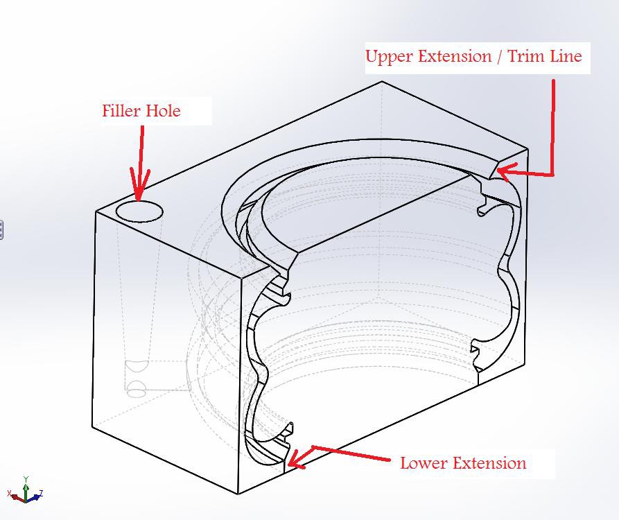
Similarly the outer mold halve is created by using the exterior boot geometry, but rather than a revolved extrusion, a revolved cut is made thru a block large enough to hold the volume needed. The outer mold block only needs to be large enough to allow a reasonable parting line width( maybe 1/4" or so) , and room for fill holes, any more than that and you're just adding time to your mold prints.
Some other consideration is given to the seat of the two molds. a distance is extended above and below where needed. The lower extension allows for the molds to orientate and seal, while the top extension is used as a vent and trim line indicator. Its better to have your silicone form past where it's needed, rather than risk it being too short if you don't allow any fill.
![]()
-
2Printing the molds
Assuming that the reader has a reasonable understanding of 3D printing, this step will be glanced over. The subject could easily be expanded on, but it would be taxing to undertake that detour in this process.
It is worth mentioning that the calibration and accuracy of a printer could limit the size of features produced. The "seam" where the mold half's join, commonly called the "parting line", will determine how accurately the molds fit together. In industrial standards, sanding the parting line is a taboo, any non conformance, miss-match or miss-shaped geometry will show greatly on the finished parts final product. Next time you have a plastic bottle around, try to find the seam where the two halves of the mold closed, chances are that it will only be found it you looked for. It's not always critical to produce industrial standard molds, but take it from someone who's had to spend countless hours polishing things, use the technology to get as close as you can, then B.S. it from there.
Printing Molds for Rubber Repairs
This project will attempt to record the production 3D printed molds, in this case for a glider landing-strut boot
 classicrockfanatic88
Discussions
Become a Hackaday.io Member
Create an account to leave a comment. Already have an account? Log In.