-
Purple BeagleLogic(s)
01/24/2016 at 18:03 • 0 commentsDrew Frustini shared pictures of the BeagleLogic cape which arrived from OSHPark.
![]()
(credits to Drew for the original pic)
For more photos, go to the Google+ post
-
BeagleLogic discussion group
01/11/2016 at 20:43 • 0 commentsBeagleLogic now has a discussion group at https://groups.google.com/forum/#!members/beaglelogic.
You are invited to join and participate in the discussion on how to make BeagleLogic better, or share your experience with BeagleLogic, any issues you faced, how you want to see this going in the future.
See you there!
-
BeagleLogic v1 cape shared on OSHPark
12/15/2015 at 10:01 • 0 commentsI saw on my GitHub traffic stats today that my original cape design has been shared on OSHPark.
Link here - https://oshpark.com/shared_projects/7qWc3cde if anyone would like to order.
[Design sharing credits - blundar]
-
Enabling channels 13 & 14
10/12/2015 at 15:15 • 1 commentThese instructions are for the BeagleLogic system image, and are now verified on a BeagleBone Black.
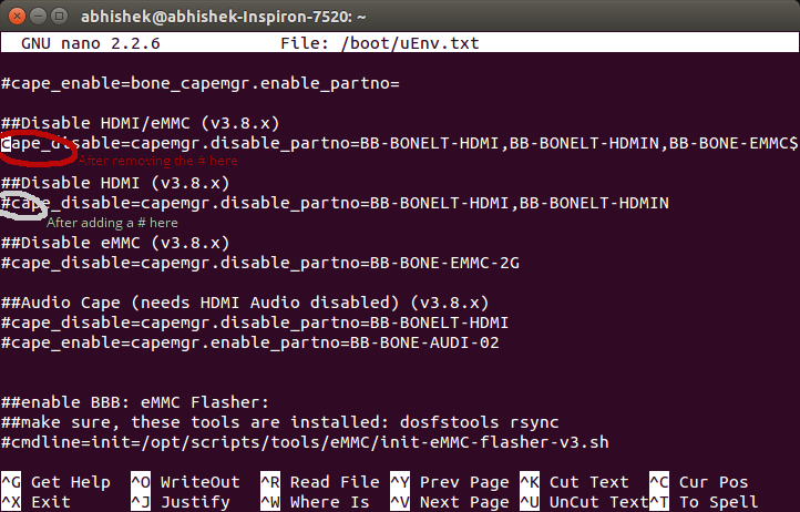
Open up a SSH to the BeagleBone and edit "/boot/uEnv.txt" in nano/vi. Scroll down a bit until you see these lines and make sure they appear the same as in this screenshot by removing a '#' from the red circled area and adding a '#' at the white circled area. Then save it and reboot.
![]()
This disables the eMMC. Now solder two 0R resistors on the bottom of the BeagleLogic cape (R8 & R9) to connect them to the logic inputs.
The device tree file also needs to be recompiled to multiplex the 13&14 pins into the BeagleLogic inputs. Download the precompiled version from here - note that this file is called BB-BEAGLELOGIC14-00A0.dtbo to differentiate it from the existing dtbo file which enables only 12 channels. Copy it into /lib/firmware.
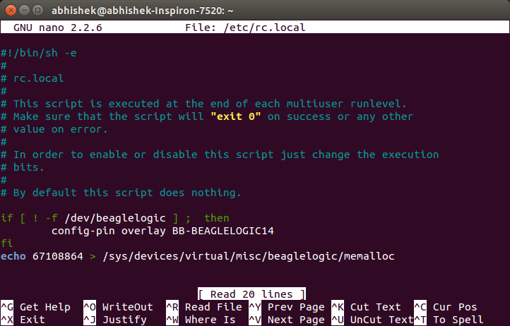
Next, we need to edit the startup script to load our new device tree overlay to use all 14 pins. For this, edit /etc/rc.local , go to the line that says 'config-pin overlay BB-BEAGLELOGIC' and edit it to 'config-pin overlay BB-BEAGLELOGIC14'. It should now look like this:
![]() Save it and reboot. After rebooting your system it disables the eMMC and then multiplexes the eMMC pins onto the PRU inputs. Thus you can use all 14 inputs on BeagleLogic.
Save it and reboot. After rebooting your system it disables the eMMC and then multiplexes the eMMC pins onto the PRU inputs. Thus you can use all 14 inputs on BeagleLogic.IMPORTANT NOTE: Do not apply signals on these channels until the BeagleBone has finished booting. It is also a general precaution not to apply signal at any pin of the BeagleBone until it is fully powered up.
[ P.S. Thanks to @David Bacungan for reporting issues in the previous version of these instructions. These have now been addressed with this version of the guide. ]
-
Best Product Finals Video
09/20/2015 at 20:50 • 0 commentsThis is the Best Product Finals video for BeagleLogic:
Judges, please take a moment to go through this note I sent to team Hackaday along with the product samples - it contains important release notes for the prototype that will be in your hands!
This is a small playlist containing the Quarter Final and Semi Final Video presentations, I recommend you go through them as well once.
Thank you for your attention.
Wishing the other Best Product Finalists and 2015THP Semifinalists the very best!
~Abhishek
-
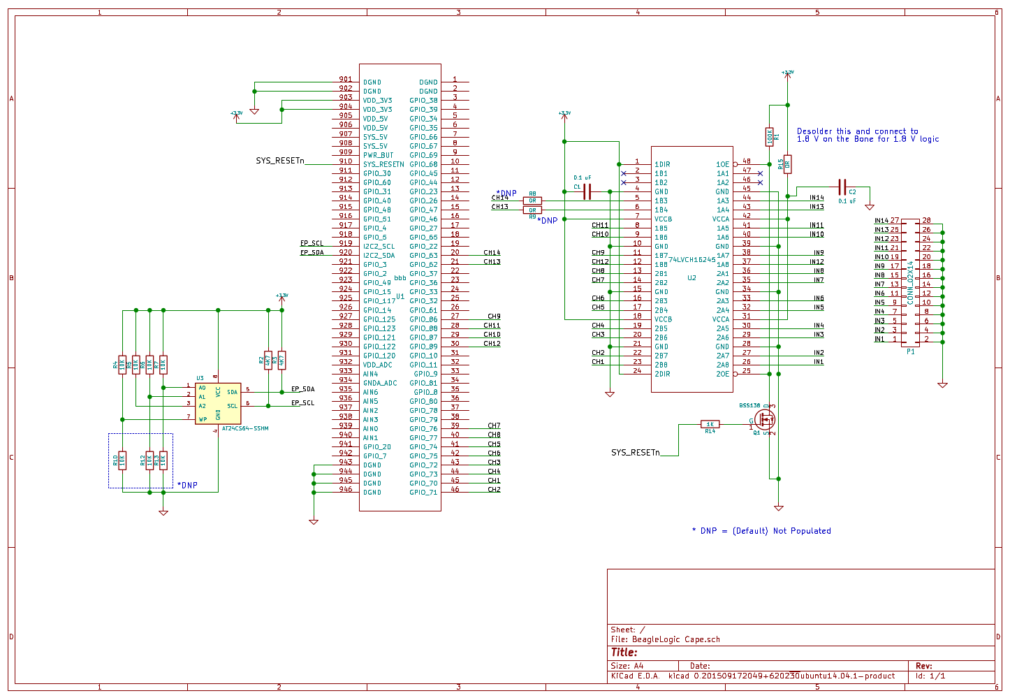
New Revision of the BeagleLogic cape WIP
09/20/2015 at 20:46 • 9 comments![]()
What's new:
Removed the cape EEPROM as it wasn't being utilized. All the configuration is handled in the BeagleLogic system Image.
Added a DS1307 RTC to keep time so that logic captures can be correctly timestamped. This will be reflected in the software as well.
Add a LDO with 3.3V / 1.8V select on Input side for configurable logic level thresholds. BeagleLogic should also be able to tolerate +/-12V logic signals, will be working out the best way to make it happen.
Stay tuned for more rev2 updates!
-
BeagleLogic Cape Schematics & Explanation
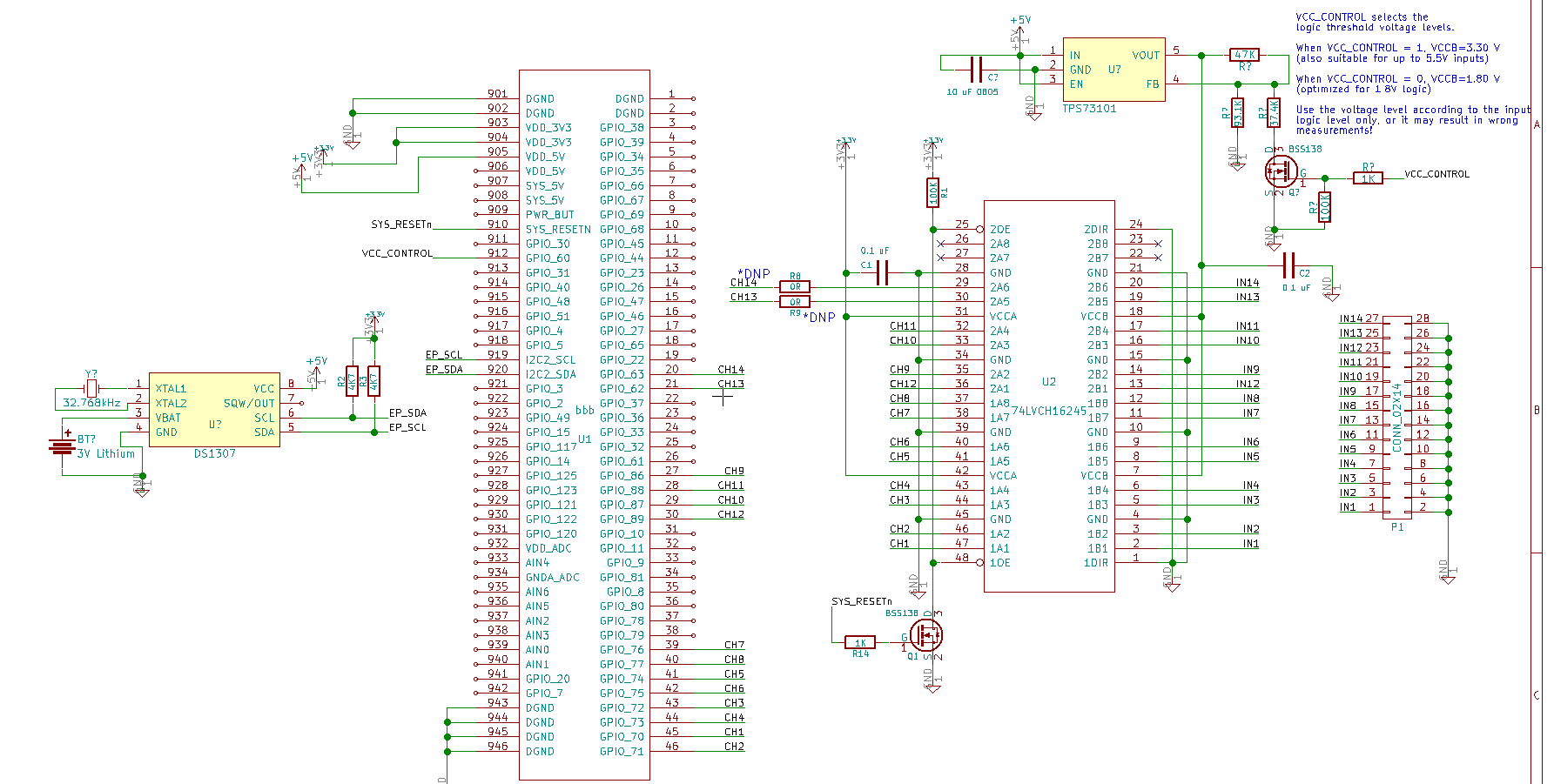
09/20/2015 at 20:46 • 0 commentsIn this log I explain the BeagleLogic cape schematic.
![]()
At the heart of the schematic is a 74LVCH16T245 logic level translator IC. This translator inputs are 5V tolerant so it shields (and up to a limited level in case of overvoltage transients) the BeagleBone Black from external circuit logic levels. Therefore with the cape you can debug TTL circuits and Arduino circuits without fear of harming the BeagleBone Black in normal usage.
The inputs of BeagleLogic are also the boot pins for the AM335x and hence must not be changed by external circuitry during the boot phase of the SoC. How do we ensure that external pin disturbances do not cause the BeagleBone to lock up at boot?
The answer is - through the little BSS138 MOSFET connected to the SYS_RESETn pin of the AM335x SoC. This pin is pulled low during the SoC boot and goes high after the SoC has booted up. When the pin is pulled low, the MOSFET is off, hence the OE pin of the 74LVCH16T245 buffer is pulled high by the 100K resistor causing all the outputs of the 74lVCH16T245 (the B rail in this case) to go high-impedance thus not disturbing the logic levels on those pins. Once SYS_RESETn is high, the MOSFET turns on and pulls OE low so that the outputs are enabled and follow the BeagleLogic inputs.
Thus using a cape not only provides a layer of logic translation but also a layer of isolation so that if connected to an external circuit with the BeagleBone powered down, the inputs do not accidentally parasitically power the AM335x SoC.
The EEPROM is there for cape configuration, however may be removed from the next iteration of capes as the BeagleLogic system image handles the configuration automatically.
-
BeagleLogic Cape Design Files
09/20/2015 at 20:45 • 0 commentsThis Project Log references the rule of the 2015 Best Product Finals in which participants are required to post Gerber and Drill files of their builds.
The BeagleLogic design files are located here on the project GitHub repository:
https://github.com/abhishek-kakkar/BeagleLogic/tree/master/cape
For the gerbers and PDF copy of the schematics and board layouts, this is the Google Drive Folder:
BeagleLogic Cape Fabrication Outputs (Generated on 21st September)
The KiCAD design files are always the latest design while the fabrication outputs are of the last hardware release. They will be updated when a new revision is released.
-
Semifinal Demo Video
08/17/2015 at 20:34 • 0 commentsJudges: Please take a few minutes to read this note that I had enclosed along with the BeagleLogic prototypes. Thanks!
Just in time, the semifinal video!
SFTP mapping is created using the File explorer by clicking on "Connect to server" button and adding the address - sftp://192.168.7.2/root ( or change to your IP ) . Then enter "root" as username and leave the password blank.
On Windows, for the same effect one can use WinSCP available at https://winscp.net/eng/download.php to browse the file system on the BeagleBone.
-
Channel Naming Convention
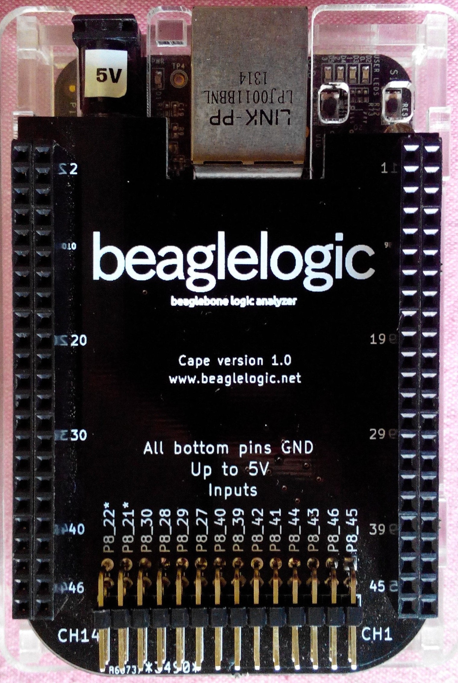
08/17/2015 at 19:36 • 0 commentsHere's the image for a quick reference.
![]()
Note that:
- Channel "x" is bit "x - 1" in the channel binary data (which is stored little endian) Right to left is channel 14 to Channel 1 ( ie bit 13 to bit 0)
- Default data captured is in 8 bits, but can be set to capture 16 bits. See sysfs attributes reference for a complete list of parameters that can be changed.
- The label alongside each channel pin is the name to be used while using the "sigrok-cli" app. So if you wanted to capture channels 1, 2 and 3 you would use the names P8_45, P8_46 and P8_43 respectively and not refer to them as 1,3 and 5.
- However if you process raw binary data, you must use the bit numbers ( channel number - 1) with sigrok to receive correctly.
BeagleLogic
Turns your BeagleBone Black/Green into a 14-channel 100Msps Logic Analyzer
 Kumar, Abhishek
