j0z0r pwn4tr0n
-
Moving to a new project...
03/15/2016 at 04:29 • 0 commentsSo I have decided to finish this up and use it for my entry into this year's Hackaday prize. I think this is just the motivation I need to complete this project. I dropped it a while ago and it has been collecting dust, but always at the back of my mind. At the time, my Eagle skills weren't really up to the task, but I have since practiced and made a few smaller board and think I am ready to tackle this task again.
https://hackaday.io/project/10161-6-inch-pi-e-ink-display
That's the new project page, as per the Hackaday prize rules. Follow/like/skull me over there to get the latest updates on this project. I will still update this project occasionally too, but the aforementioned one will be the main headquarters for updates. It is a placeholder now, but I'm going to fill it with all the research and relevant information from this project shortly. Thanks!!!
-
Short update
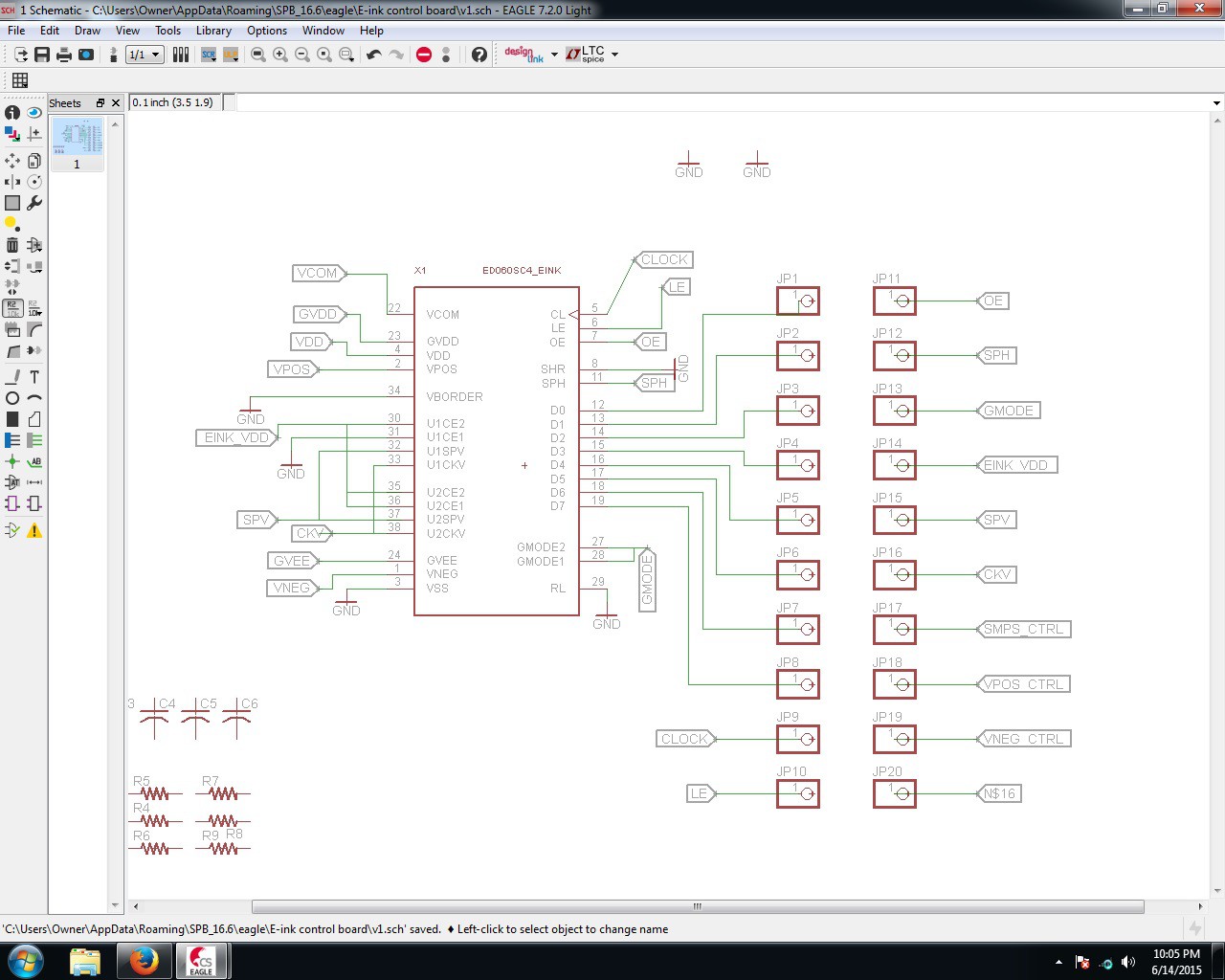
06/16/2015 at 12:50 • 1 comment![]()
I finally have that connector wired up in Eagle. I still need the power circuitry, but I'm getting there. And it looks like such a tangled mess, lol
-
Slowly coming together
06/11/2015 at 00:41 • 0 commentsI recently graduated and started a new job and it has kept me pretty busy lately and I haven't had a lot of time to hack on my projects. Plus this one is a lot like work, the board design part is probably the least fun, lol. I'm almost done with the schematic, it has been hard to find all the libraries for the parts that aren't already included in Eagle. There was a small trimmer resistor that I ordered that I'm gonna have to make a library for if I can't find it elsewhere. Anyway, I made this project update just to share my current BOM, which is still incomplete (missing the LT3463), but gives a good idea of the price breakdown. One of the mistakes I made that I'm having to workaround is that I didn't order all of the components in the same size. There's some 1206, some 0603, and some 0805 because I sorted by price and didn't think about packages when I was ordering. It's not that big a problem, but I have to be very careful and triple check everything while making the schematic. The total cost of all this without shipping is only $7.14!! Without further adieu:
Part Name in Schematic Quantity Mouser Part # Price(each) D1 1 576-SPHV36-01ETG-C $0.40 C2 1 81-GRM188R61E105KA12 $0.04 C1, C3, C4, C5, C6 5 77-VJ1206V475MXQTBC $0.06 L1, L2 2 963-LBR2012T100K $0.10 R9 1 594-MCT06030C2003FP5 $0.10 R10 1 594-MCT06030C1202FP5 $0.06 R8 1 754-RR0816P-164D $0.09 R2 1 594-MCT06030C4702FP5 $0.06 R1, R3, R4, R7, R11, R12 6 594-MCT06030C1002FP5 $0.10 Rv1 1 81-PVZ3A103C01B00 $0.17 Q1 1 942-IRLML6402TRPBF $0.56 U1A 1 511-LM358P $0.39 U5 1 926-LM79L15ACMX/NOPB $0.76 U4 1 926-LM78L15ACMX/NOPB $0.67 U2 1 798-FH2639S0.3SHW05 $2.74 -
Parts in!!!
05/19/2015 at 02:16 • 0 commentsI just graduated and moved on to a new job, so things are kind of hectic in my life right now and I haven't had a lot of time to devote to this or any of my projects. I thought I would have the board together by now, but the schematic is more complicated than any I have done so far and is taking longer than I anticipated. I'm thinking about going the easy way and just make a breakout board for all the pins on the crazy connector, but we'll see what a couple of weeks does for that decision. The connector will be the hardest component to solder, so if I make a breakout, I might as well just go all the way with a full custom board.
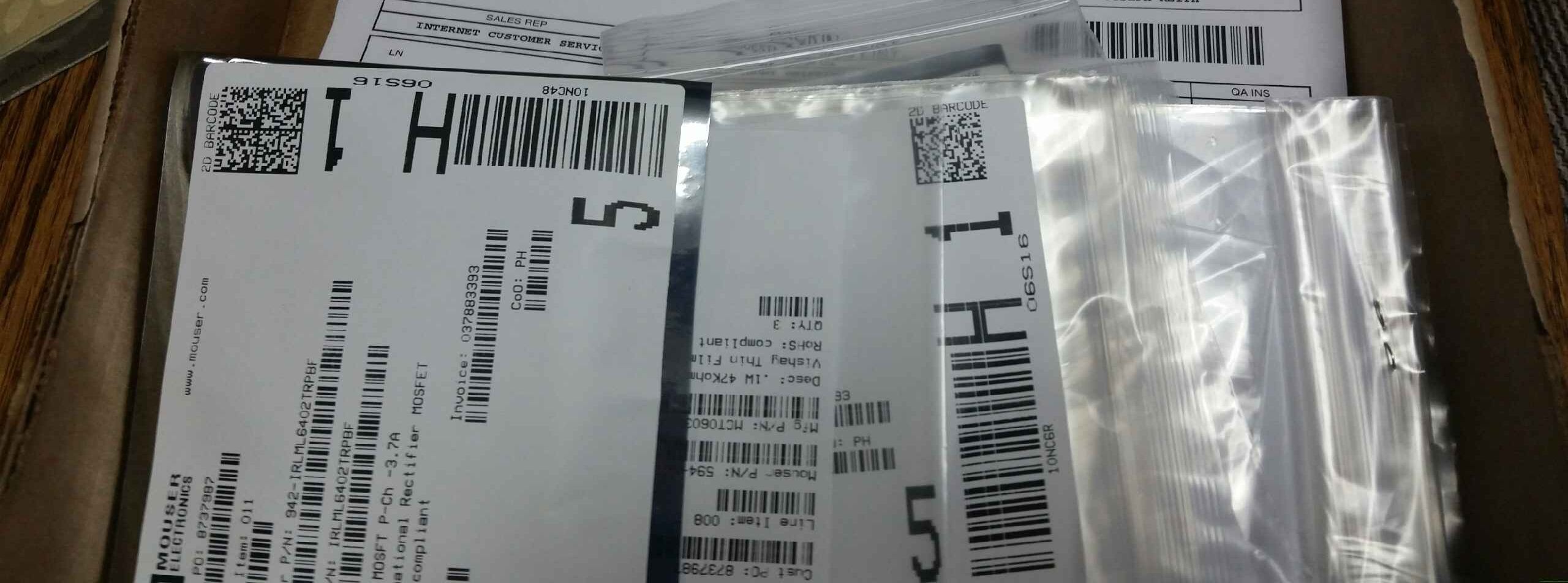
![]()
Parts came in! I put in an order with Mouser and had them in less than a week. Plus the total was around $14. That was with shipping and ordering multiples of some of things I could use in other projects. One of my as yet unstated goals in this project is to keep it as cheap as possible, so I'm thinking even with a custom board, this might be significantly cheaper than the OLPC: the only similar commercial offering.
![]()
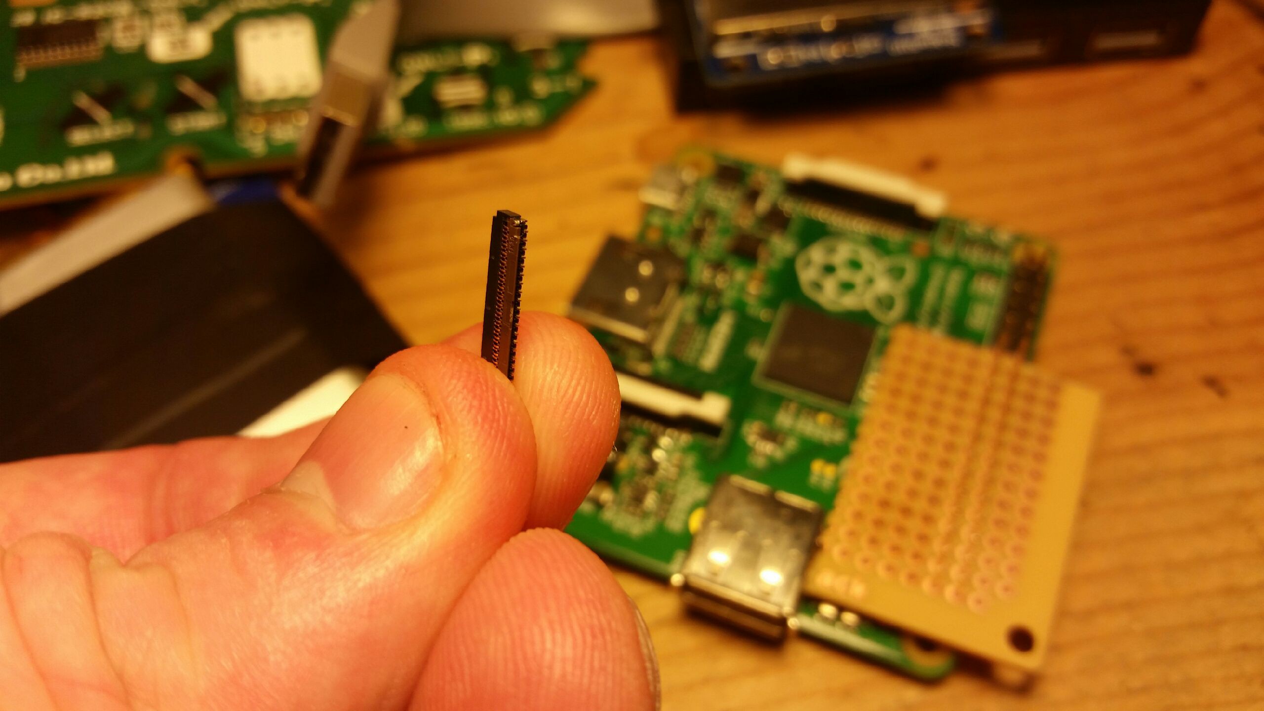
Here's that dastardly connector! You can barely see it in the picture, but it has 15 pins on each side! This will be the most difficult part I have soldered so far. The other components are SMD, but I got all the passives in 0805. I'm going to update the parts list soon so I can do a price breakdown of what I have so far.
![]()
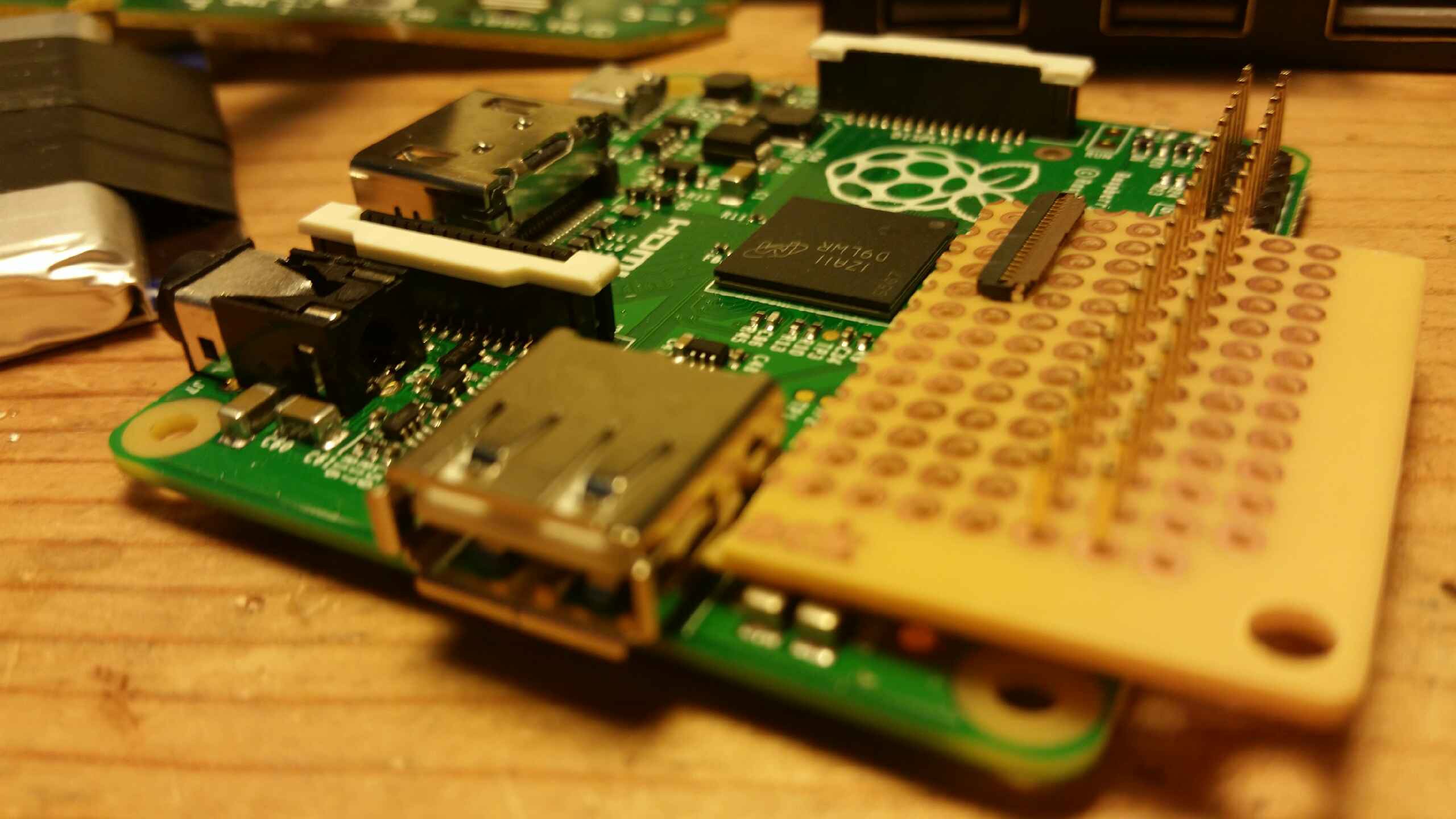
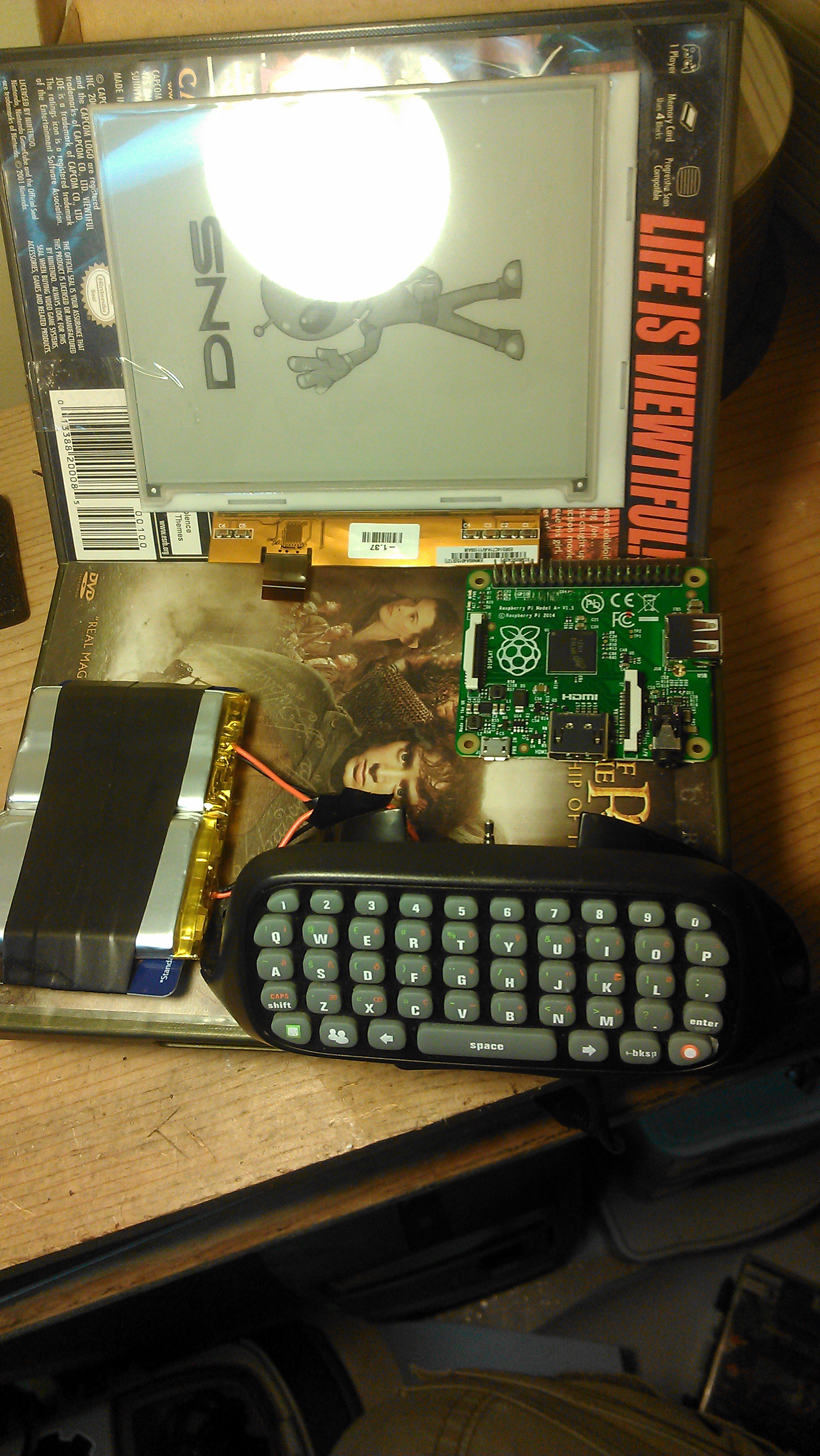
This is how small I'm hoping to slim the board down to, so it and the Pi can fit behind the screen. Note how it is thin enough to be shorter than the singular USB plug.
![]()
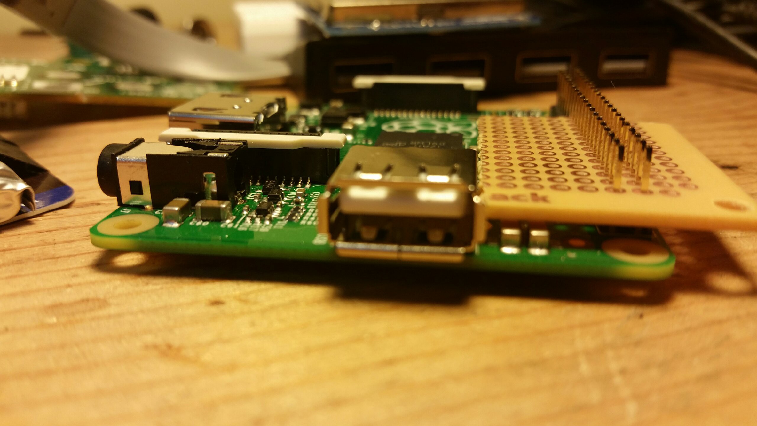
Slightly different view to show what I'm going for. Hopefully a small board that can reside in the footprint of the Pi and turn it into an e-ink laptop!
![]()
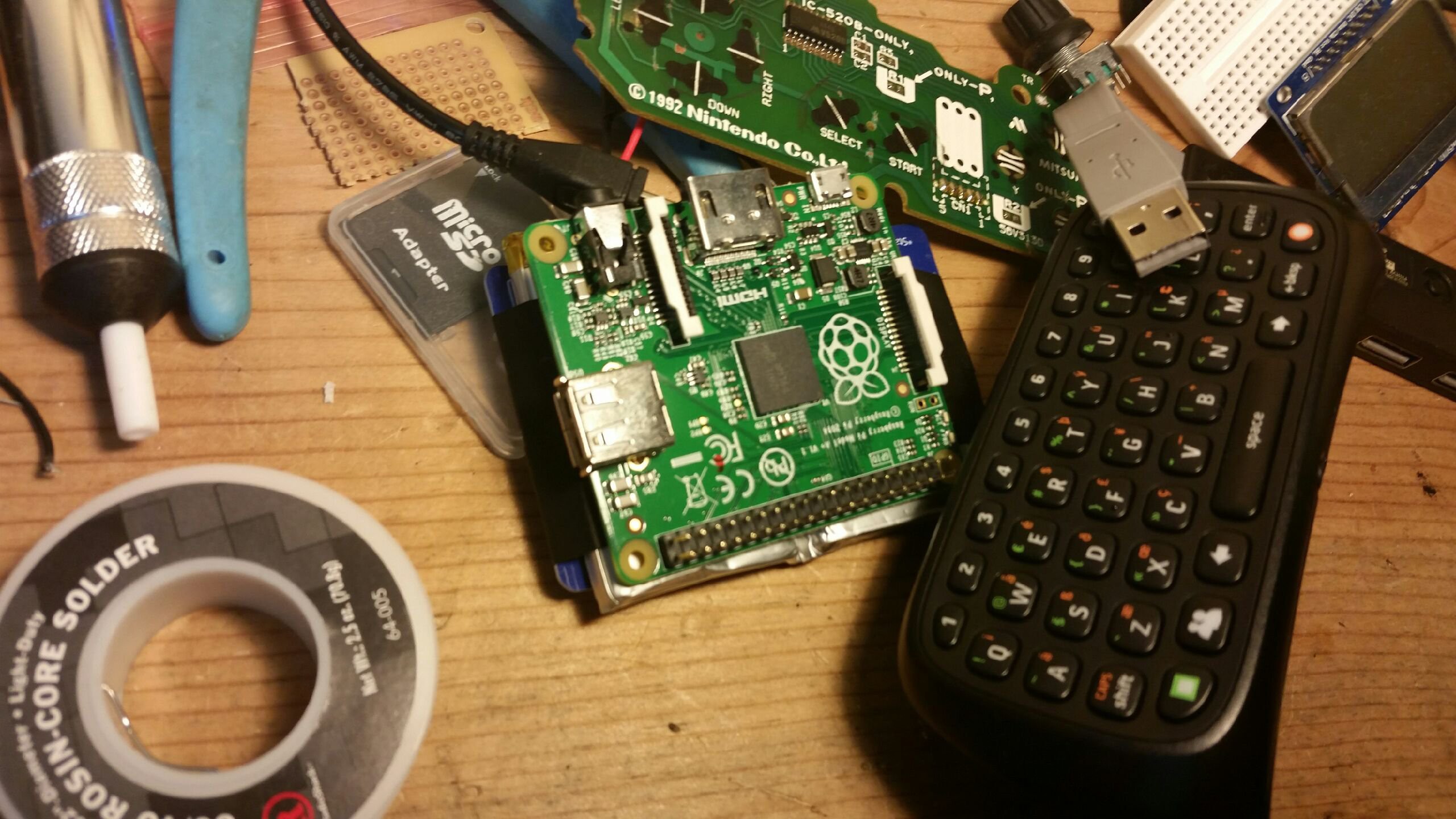
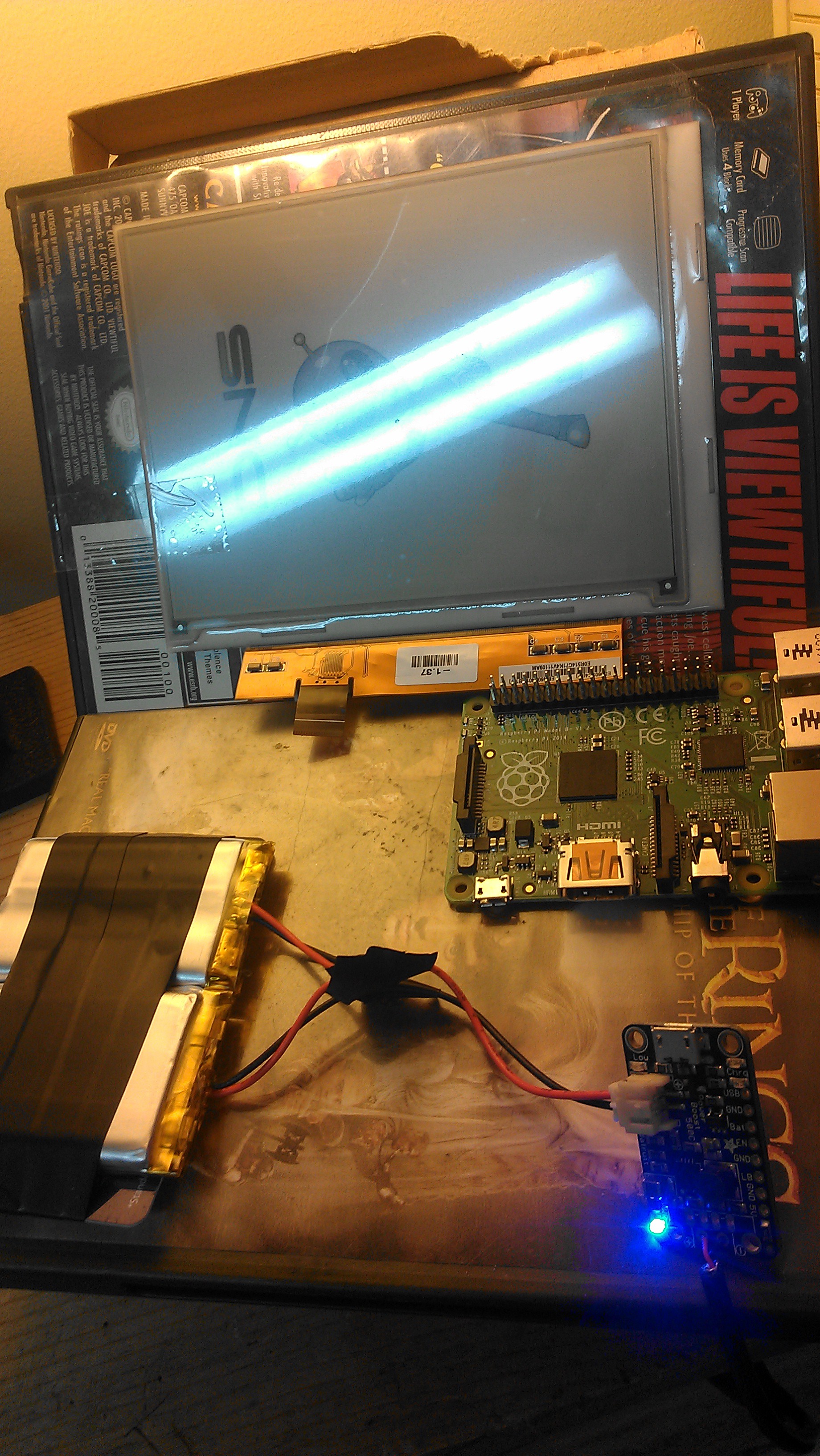
This is the mess of a computer I have so far (not all of this is related, points if you can guess which things don't belong). A 3D printed case would be amazing, and it would be the first time I have used a custom enclosure that wasn't made with hot glue!
I finally formatted me up a card for the A+. I'm gonna get the compiler going next time I sit down with this and see if I can compile a version of the code with the GPIO pinouts from the Pi instead of the original board the code was made for. I'm sure shenanigans will ensue, and fun will be had at all junctures, lol.
-
Research
04/21/2015 at 18:51 • 0 commentsThe first step of a big project like this is doing the research to see what work has already been done and what needs to be done. In reviewing the information provided on the websites in the description, I think I have found all I need to make this work with a few modifications.
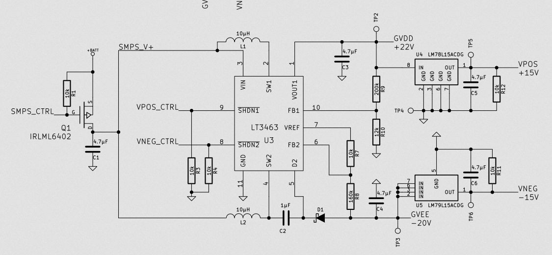
Petteri Aimonen of the website essentialscrap.com has put together a pretty in-depth look at the ED060SC4 screen and how to drive it. His website has numerous links to datasheets and brochures on e-ink displays as well as diagrams showing the pitfalls he has encountered in making this display function for his needs. His project drives the screen with an STM32 programmed in C. He also has an excellent schematic which uses Texas Instruments op-amps to supply the necessary positive and negative voltages.
This is an excerpt from his schematic, I'm going to use this part for the voltage generation:
![]() I should be able to use that part without any major modifications. The other part drives the screen with the micro controller:
I should be able to use that part without any major modifications. The other part drives the screen with the micro controller:
This part will be roughly the same, but the micro controller will be a Raspberry Pi instead of an STM32. There's 8 data lines and a few pins dedicated to clock signals, screen mode changes, and turning the control voltages on and off in the correct sequence.![]()
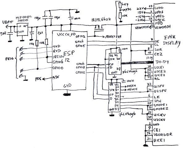
SpriteTM has a similar project, using an ED060SC4 paired with a ESP8266 to make a wifi-enabled whiteboard. There are a few significant differences between his version and Petteri's, the biggest being that he uses a shift register to clock the data in since the ESP8266 doesn't have very many exposed GPIO to work with. Here's the relevant portion of his schematic:
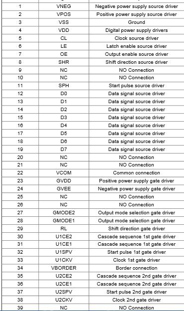
The screen has a 39-pin connector, although a few are NC (not connected). Here's the datasheet showing what all those pins need:![]()
The schematics and information from the essentialscrap website are more applicable to my usage scenario, but I may adapt the shift register after I get a prototype working. My next concern now that I have a schematic is the board to drive it. I'm still debating making a board in KiCAD or just prototyping on a breadboard where I can modify the design to suit my needs.![]()
After that, I need code to get my pixels onto the screen. Petteri Aimonen has posted his C code on github, and I'm hoping that I can just change his pin definitions to the GPIO used on the Raspberry Pi and it will just work, but let's face it; it won't be that easy.
While I was doing research, I was also playing with some of the components to get an idea of the layout. For some reason, the final layout drives my design decisions so it's one of the first things I envision. Also this is the first Raspberry Pi A board I have owned, and they are so small and cute!!!
![]()
![]()
One last tidbit for this update: Power!!! Some back-of-the-napkin calculations tell me that this contraption should pull about 250 mA per hour, and even this only if the screen was constantly updating. If these calculations are correct, I should be able to get 20 hours of operation from my 5000 mAh battery pack that's pictured above. This is also good because the solar panel I'm eying supplies about 330 mA per hour, which means I could charge it and use it at the same time.
That's all for now, thanks for all the follows and skulls!!! It's great motivation to keep me working. My next step will be to replicate the schematic and make the e-ink display something.
-
Display arrived!
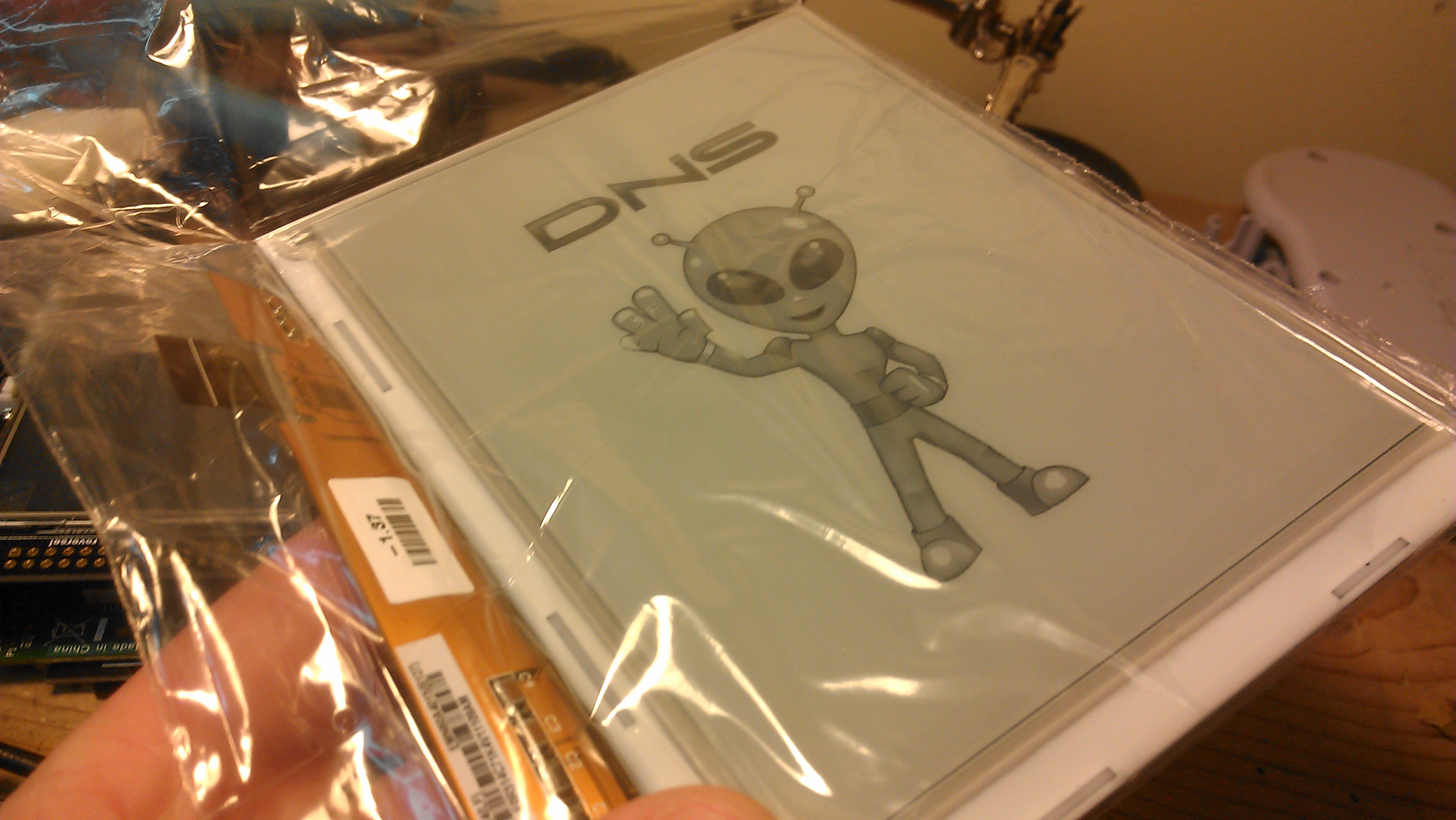
03/11/2015 at 03:28 • 0 commentsThe display came in from Shenzen today. It is much thinner and lighter than I imagined. If you have ever tabbed solar cells, it seems to be only marginally thicker.
![]()
It still has the test image displayed:
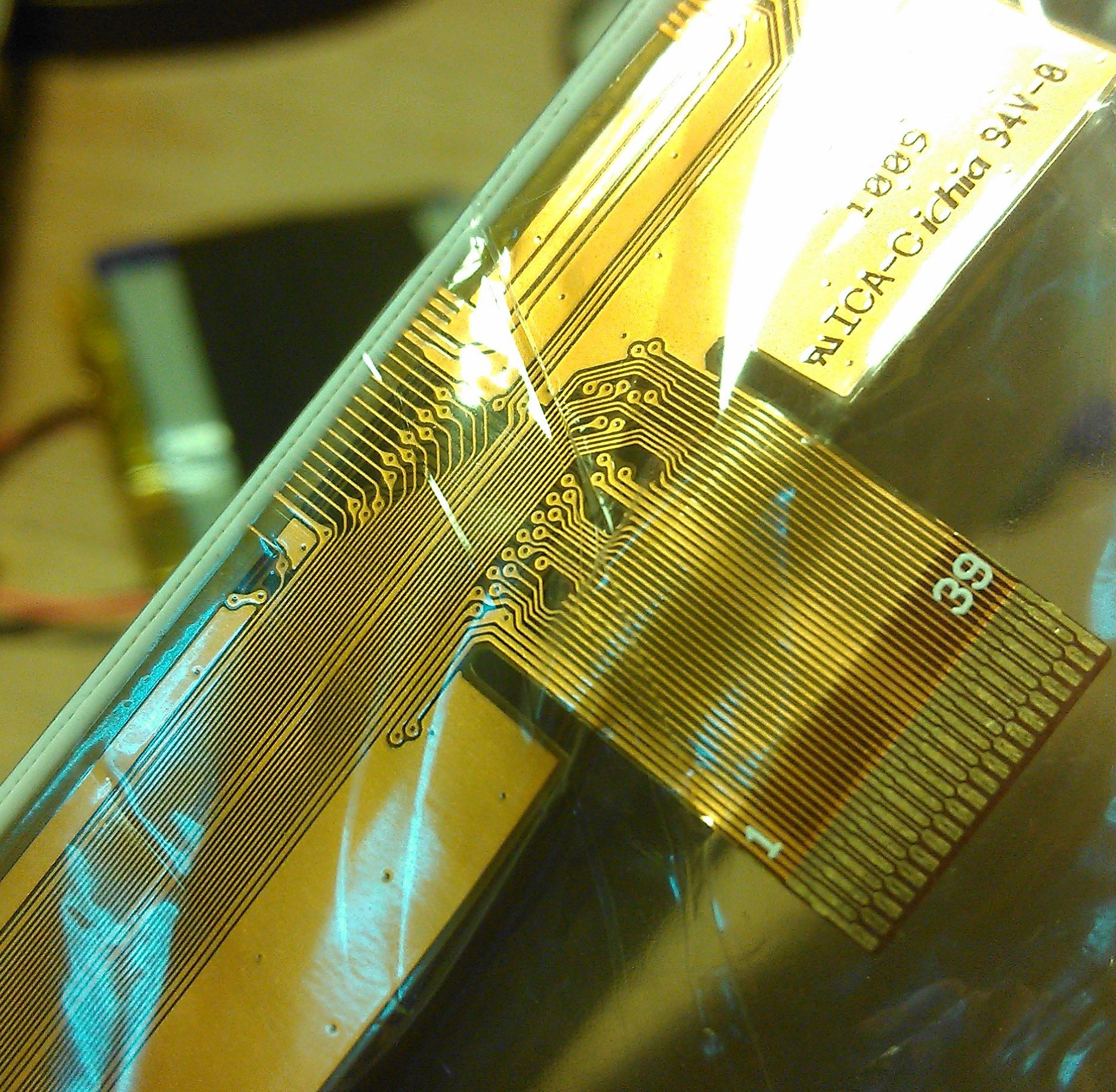
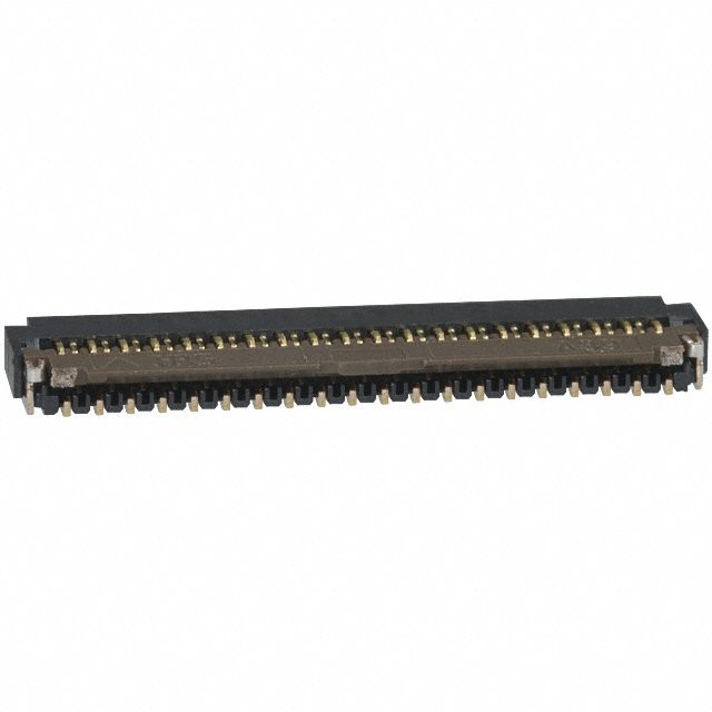
![]() I thought it was going to take significantly longer to arrive, so I haven't even put together the list of necessary components. I'm working on that now, these displays require some crazy voltages, plus plenty of passives to support the op-amps. The hardest part is the 39 pin FPC connector to mate to this ribbon cable:
I thought it was going to take significantly longer to arrive, so I haven't even put together the list of necessary components. I'm working on that now, these displays require some crazy voltages, plus plenty of passives to support the op-amps. The hardest part is the 39 pin FPC connector to mate to this ribbon cable:![]()
I found the connector on DigiKey, I will update the component list whenever I get the rest of the parts sorted out.
![]()
The next step is to design up a PCB so I can do some testing. I'm thinking something like a breakout board with just the data lines exposed, but I'll have to see how feasible that actually is. The final product should have a shift register to reduce the number of pins needed to interface with the display, but I'm not sure if that will be fast enough. Only time and experimentation will tell.
 I should be able to use that part without any major modifications. The other part drives the screen with the micro controller:
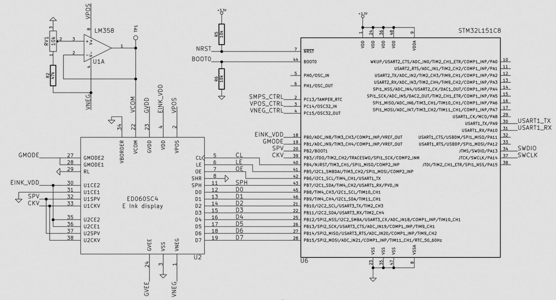
 I thought it was going to take significantly longer to arrive, so I haven't even put together the list of necessary components. I'm working on that now, these displays require some crazy voltages, plus plenty of passives to support the op-amps. The hardest part is the 39 pin FPC connector to mate to this ribbon cable: