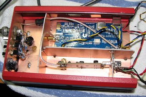
This whole project was inspired by the many different distribution amplifier designs that I've seen put into service for 10 MHz reference oscillators. I finally ended up going my own way, but it was really interesting to see the many approaches. Aside from the dist. amplifier, this unit also has 5V CMOS outputs (easily scalable using R-dividers to 3.3V, etc.) and a built-in comb generator with selectable rate.
I think the best way to understand the design is to look over the schematic page-by-page. I'll start with the power supply (p4). The 24V input is applied to U11 an Infineon BTS5090-1EJA ProFET smart switch, and the input of U9 a Sanken DC-DC converter module. The ProFET is the solid-state-relay that ultimately routes the 24V to the Rb oscillator. The DC-DC converter acts as a 10V pre-regulator. The 10V, in turn, is regulated down to 5V for the logic and CMOS circuitry, and to a switchable 9V (really more like 8V) supply for the analog distribution amplifier. An Infineon TLE4470 dual LDO U10 performs both of these functions.
Next, the RF distribution circuits on p5 are worth a look. The Efratom LPRO-101 oscillator connects via J14. The LPRO-101 has about +8dBm of 10 MHz output power. This is applied to a passive splitter X6, to result in two branches each about +5dBm. The first branch is slightly attenuated to +2dBm, then amplified by U13 to about +20dBm output. This is applied to a passive 4-port splitter X5 to yield four ports each at about +13dBm. Each of these four outputs is then made available as a SINE output on the front panel.
The second branch from X6 is applied to a Sine-to-Square converter (see p.3). This is simply a 74ACT08 quad AND gate. Section U8A is configured as a sine-to-square converter. The other three sections U8B,U8C,U8D are each responsible for providing a CMOS logic high drive (+/-24mA) output to the front panel.
The output of U8A is also applied to a comb generator circuit, which I have completely copied from an old issue of Ham Radio Magazine (see schematic p.1 for credits). This is a circuit that I've used for a long time, so I figured I'd built it into my Rb timebase! My contribution was to add the 3-8 decoder U4 that will illuminate one LED depending on the comb rate seleced.
Finally, the microcontroller on p.2 ties everything together. It is primarily responsible for monitoring voltage and the BITE signal from the Rb oscillator, and shutting down if anything goes wrong. Control switch conditioning, a Neopixel status LED, and some ADC input buffer circuits round out the rest of this page.
 tomcircuit
 Ted Yapo
 Nick Sayer

 DainBramage