 Hacker404
Latest Status Update:
I have discovered a laminator on ebay for $60 (AUD) that has plenty of room inside and looks like it may heat to 170 - 200 °C. So it may well fit the need straight out of the box. I'm expecting it to arrive in the week starting 23 March. I have added some notes at the end of this 'details' section about the original $15 laminator and code.
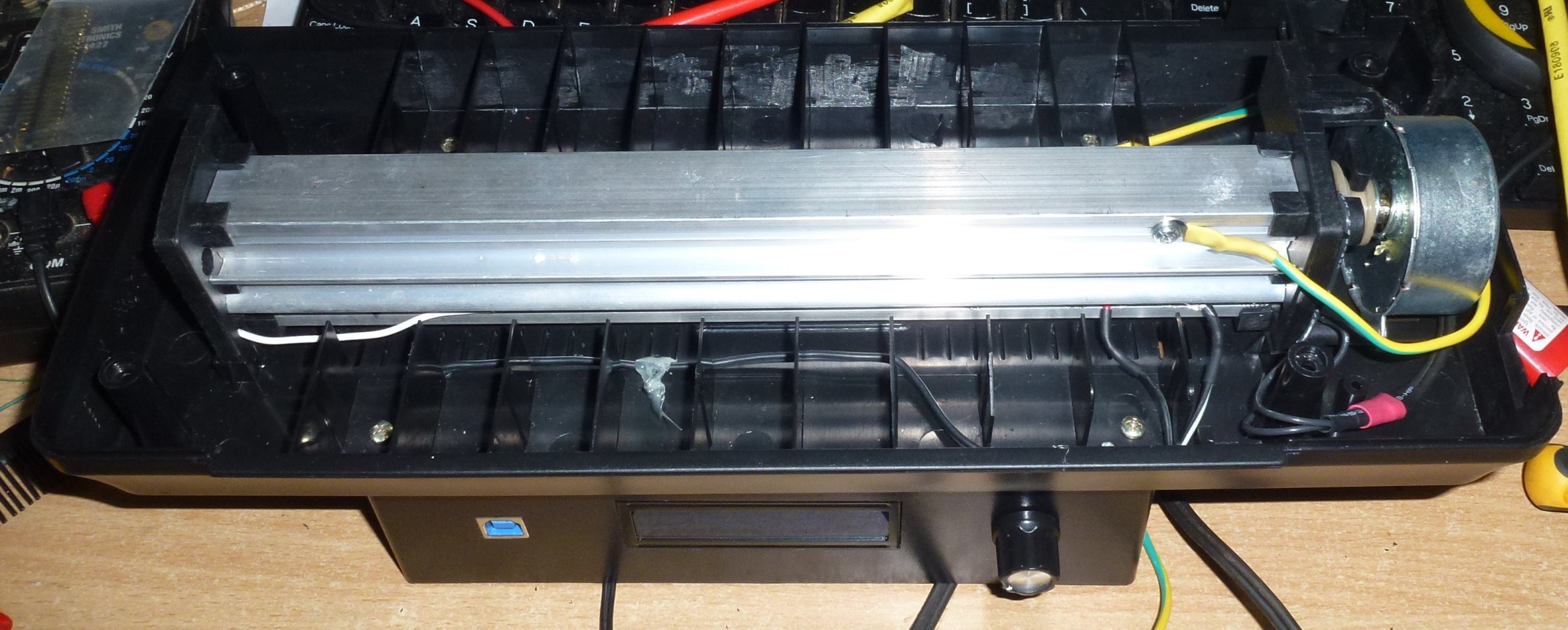
I have received the $60 laminator and it looks like a cost down version of the one used here - http://hackaday.io/project/3363-apache-al13p-laminator-one-pass-pcb-toner-xfer
It has a few bends where it shouldn't and moves around a bit when the PCB goes through so I will pull it apart and take some pics. It actually will work straight out of the box with max heat setting.
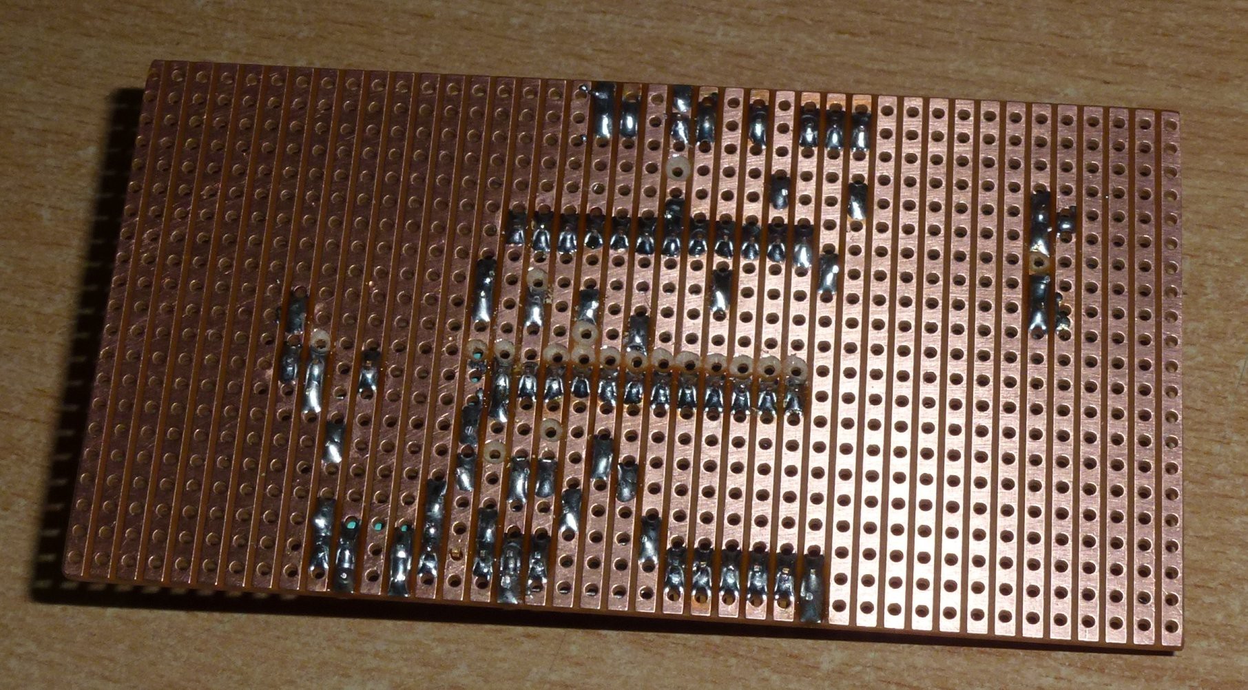
I am working with strip board because well - I don't have a fuser for toner transfer lol.
I started a power control board to control the heater and motor -
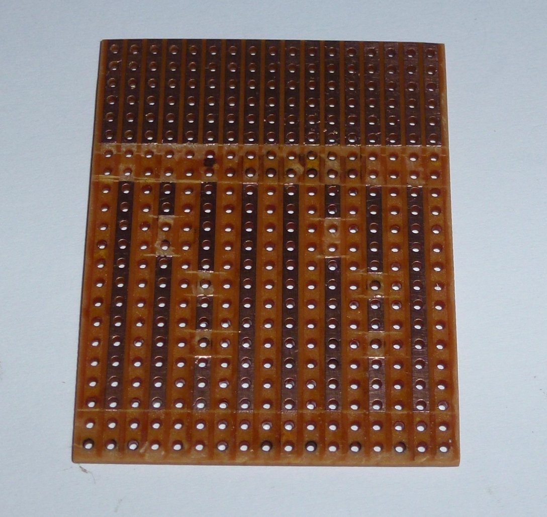
Mark out parts -
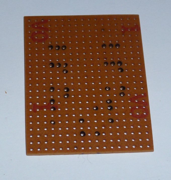
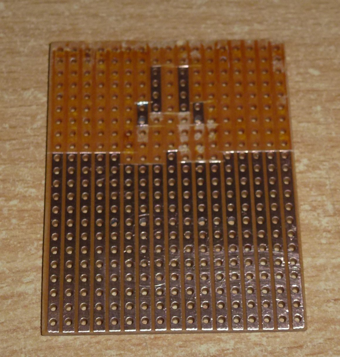
Done -
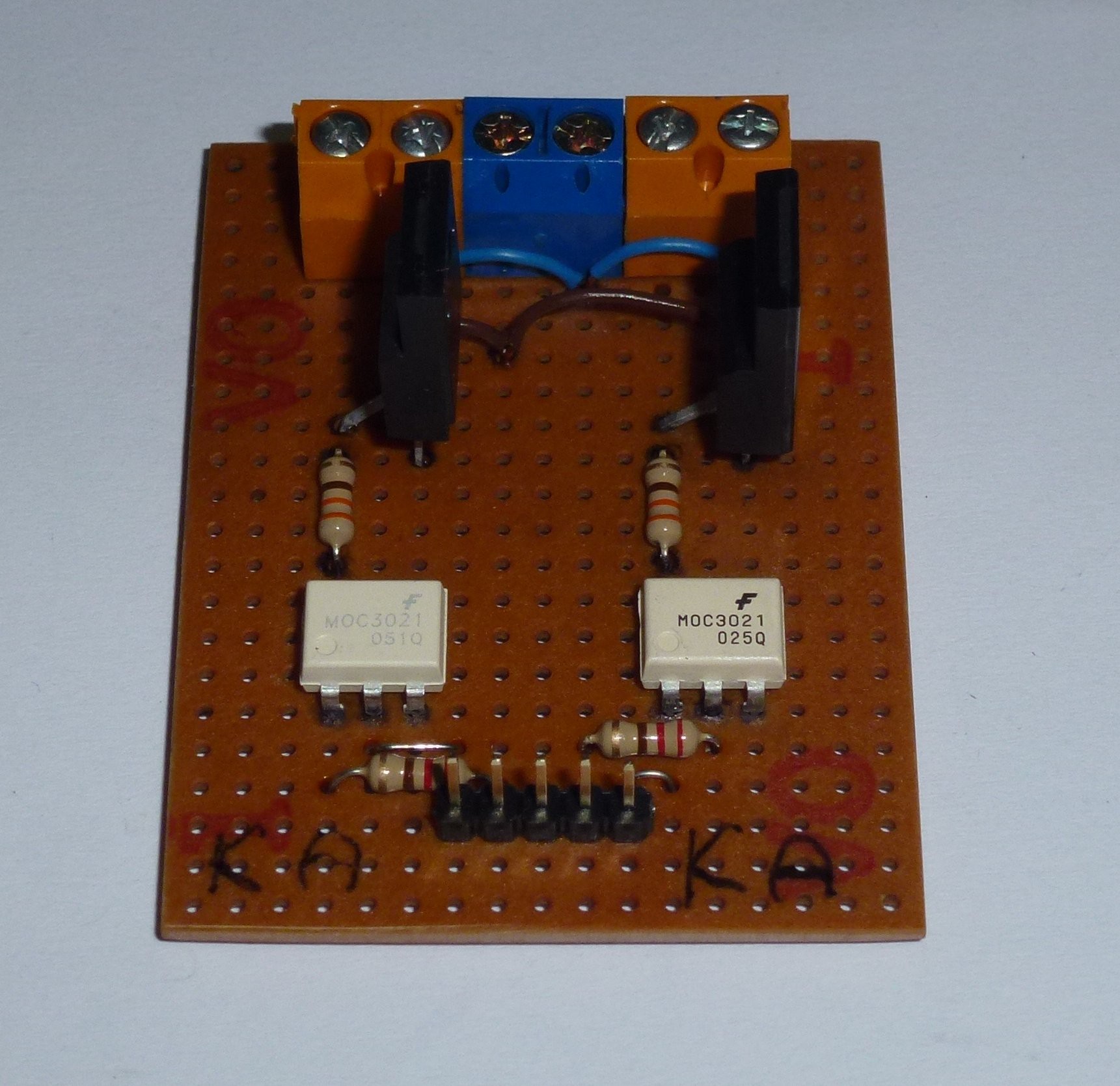
Just a couple of opto-couples (MOC3021) and TRIAC's (BT137).
I need a power supply but because of the synchronous motor this laminator has, I also needed a reference to sync to mains frequency (more later).
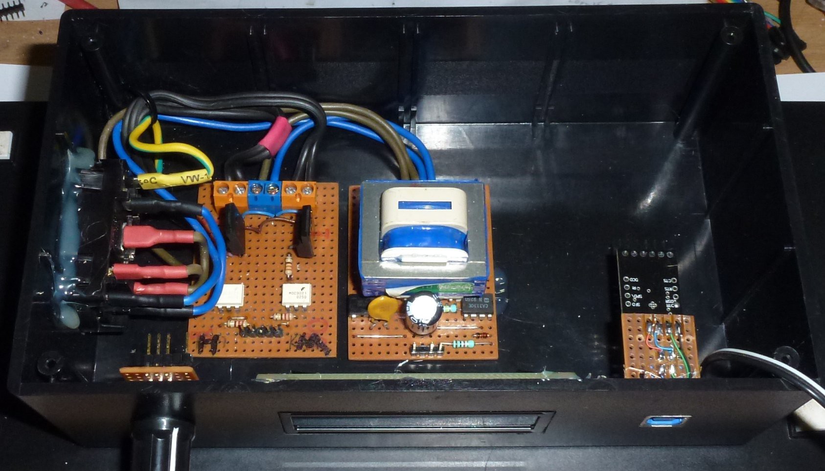
The power supply -

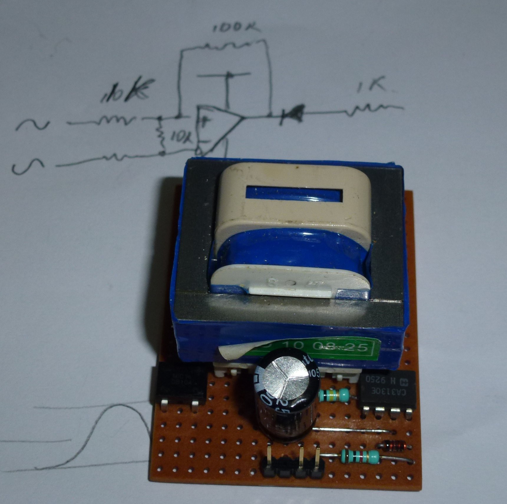
The chip on the left is just a bridge rectifier. The chip on the right is a op-amp (CA3130). It is to generate interrupts to the micro controller in sync with the mains voltage. I chose this op-amp because it is a low voltage single rail chip. It also has a voltage reference that I didn't use.
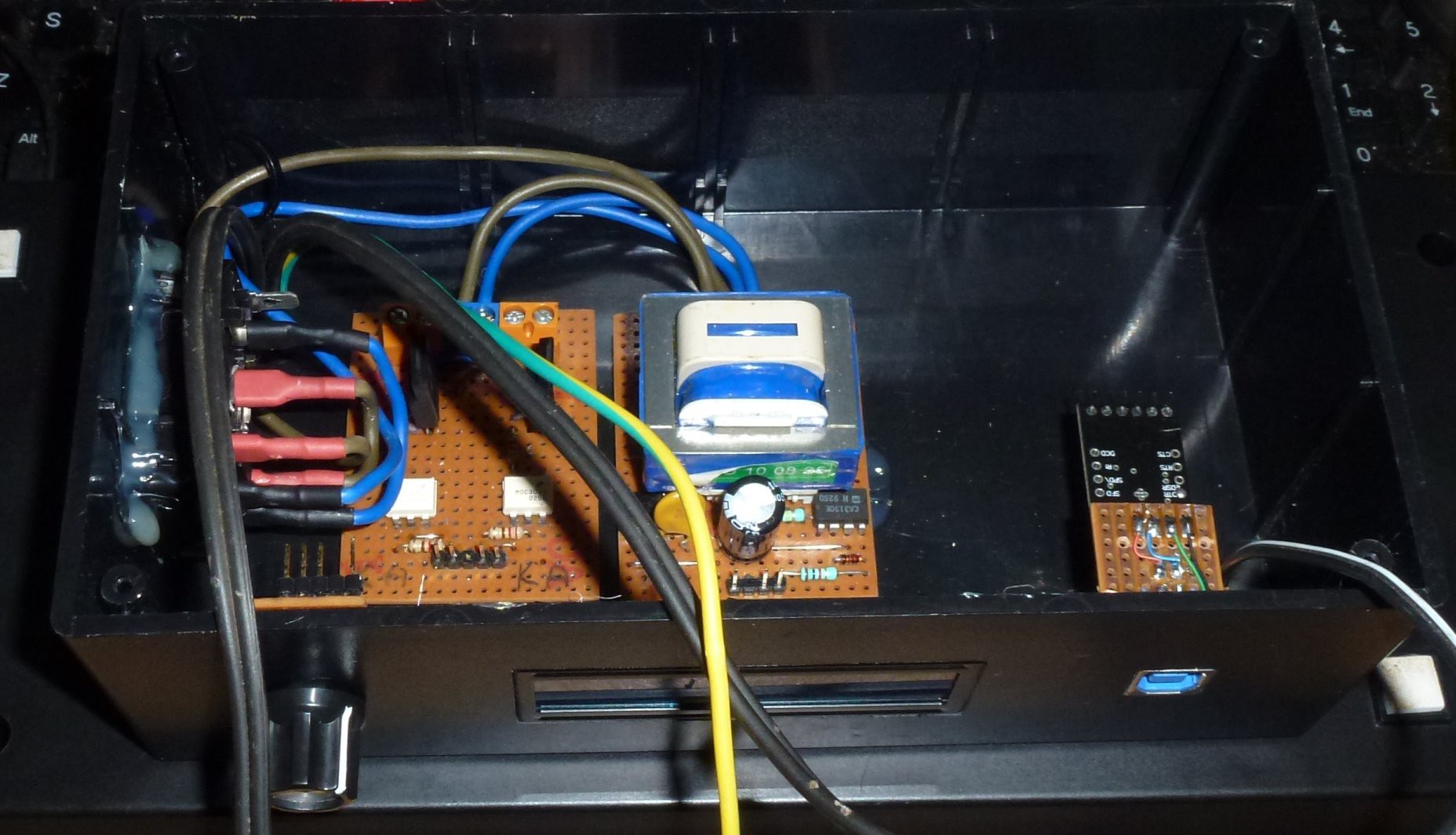
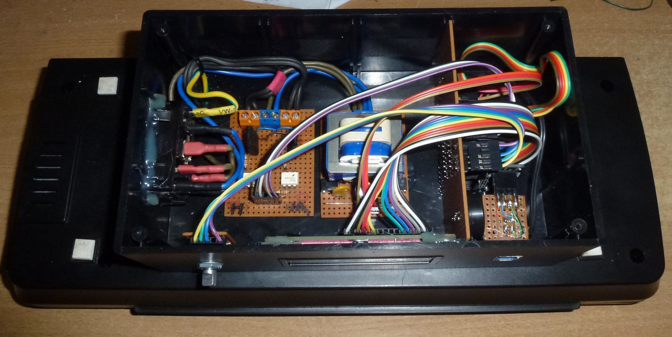
There wasn't any room for circuitry in the laminator so I decided to attach a box underneath it.
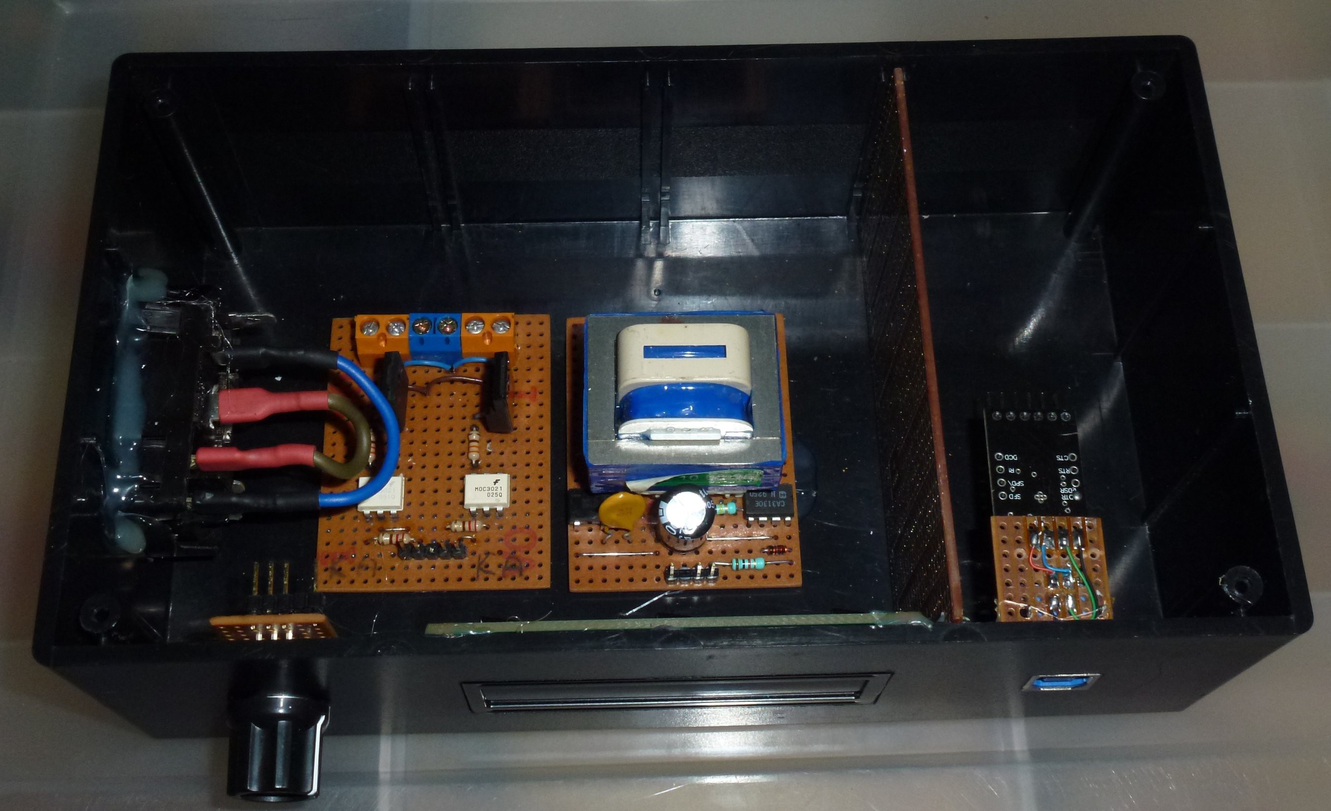
I also added a USB port for programming. A rotary encoder / switch for input and a LCD (1602) display. I glued the Mains voltage circuit boards in place for safety reasons. I didn't want them moving around and bumping the low voltage circuitry.
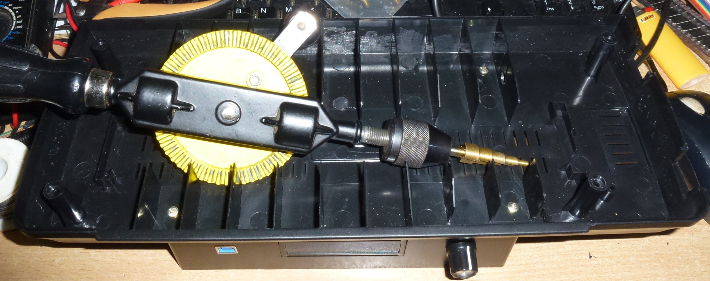
Then screw the box to the bottom of the laminator.
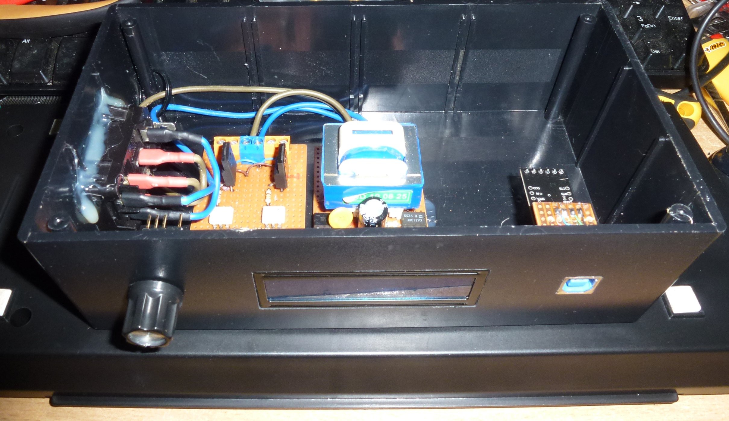
Then I did the mains wiring, keeping it neat.
I bought some PTC temperature sensors on ebay but they where too small to mount so I decided to use a common diode (1N4148) as a temperature sensor as the junction voltage will decrease as temperature increases.
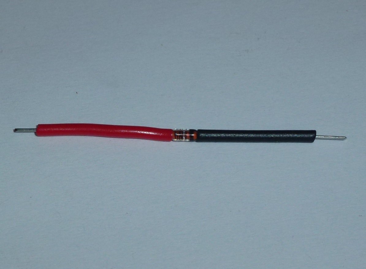
I wrapped it in foil and then pushed into the heater housing of the laminator.
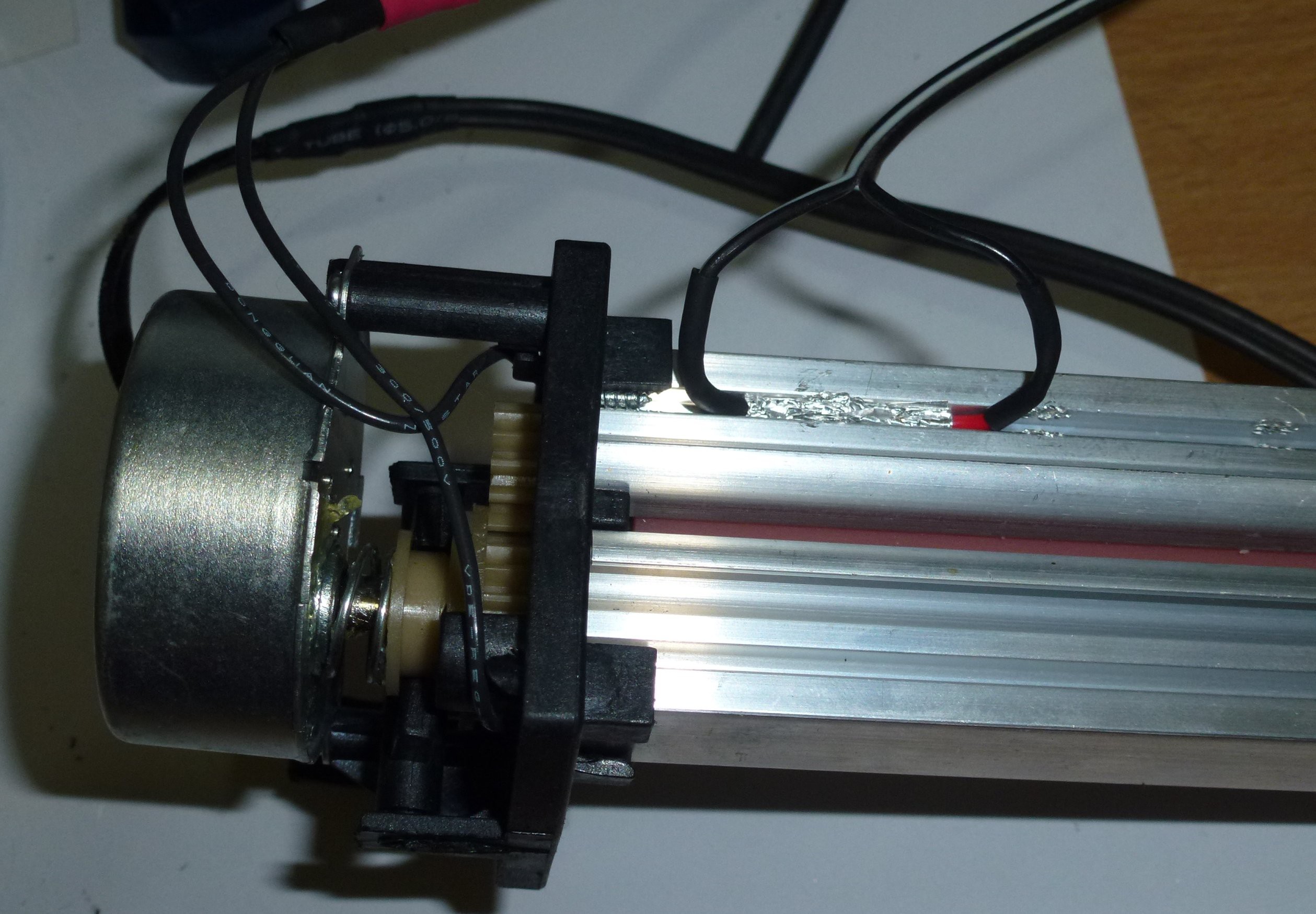
I wasn't happy with the fact that the original laminator was a double insulated device. For safety reasons you should never push anything conductive into a double insulated device like ... well a copper laminated PCB! So I earthed the metal parts in the laminator: heater and motor.
Then I had to build some brains for it. I cheated and used a Arduino Pro-Mini. Fuseduino? Still all on strip board.
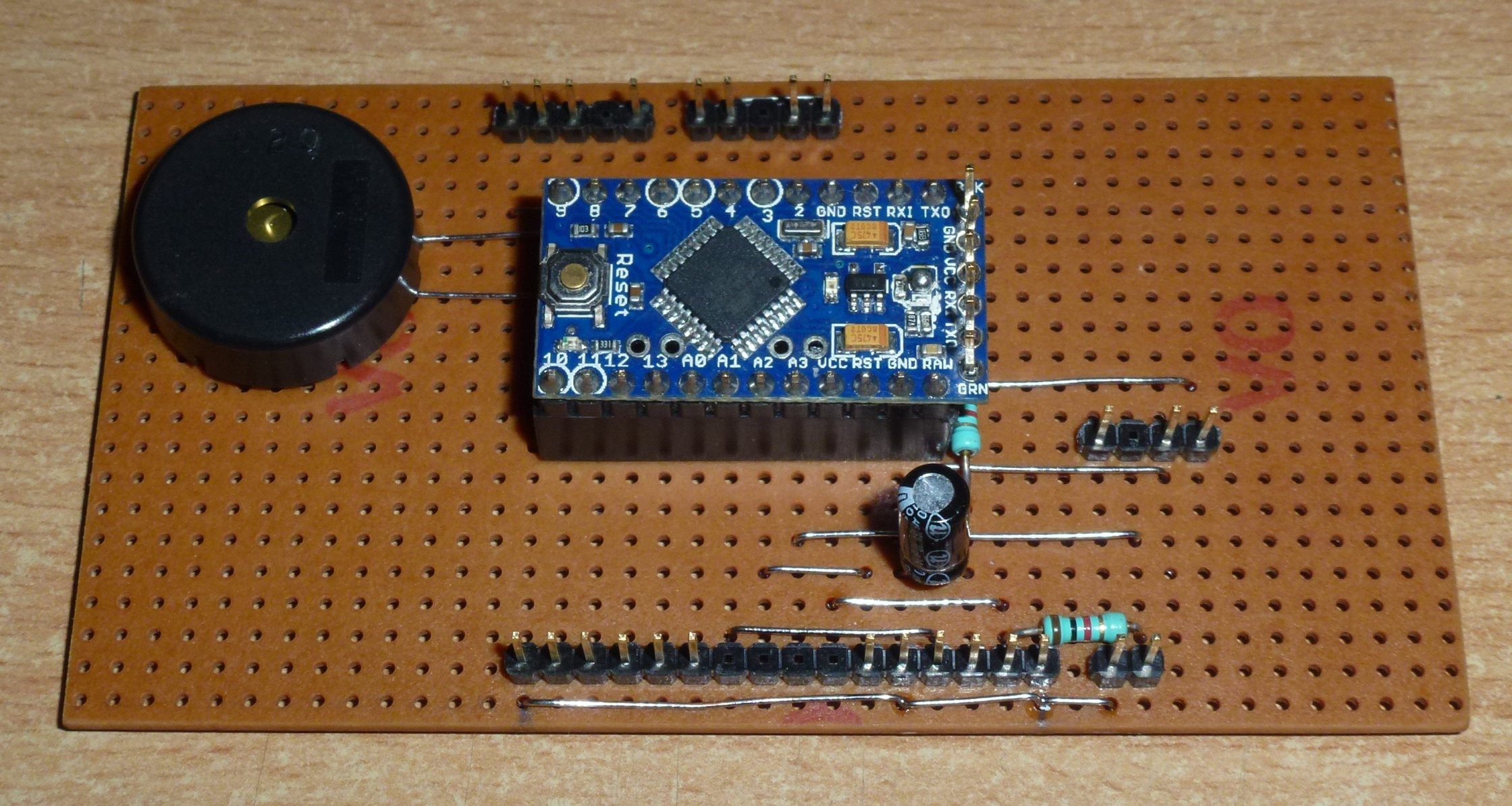
Then all in the box.
Then the problems started ... I mean I started coding.
My first problem was that I was getting erratic interrupts from the power supply board. I didn't know what was going on except that some times the interrupts were as close as 8 uS apart and sometimes they were at 20 mS apart as they should be.
I don't have a scope so I wrote some code to monitor the interrupt pin, store the data into an array (at high speed) and then send it through the serial port at a lower speed. I then put the data into some JavaScript and used a browser to graph it.

What I found is that I was getting 4 major transitions per cycle and a lot of noise triggering near the the major transitions.
I then realised that I had left out one resistor on the power supply board that was now glued into place.
After considering putting parts onto the glued in board, I decided to try a software fix.
It was dead simple, I just had to ignore any interrupts that were less than 3/4 of a cycle after the last. ie less than 15mS (for 50 Hz).
I then found that I could slow the motor by giving it 10 cycles of power and then stopping the power for 'x' cycles. The motor is synchronous so this is the only way to regulate speed.
After some experimenting with code for the heater / motor / sensor, I had an oops moment when I coded for the heater to be on when the motor wasn't running.
And ...
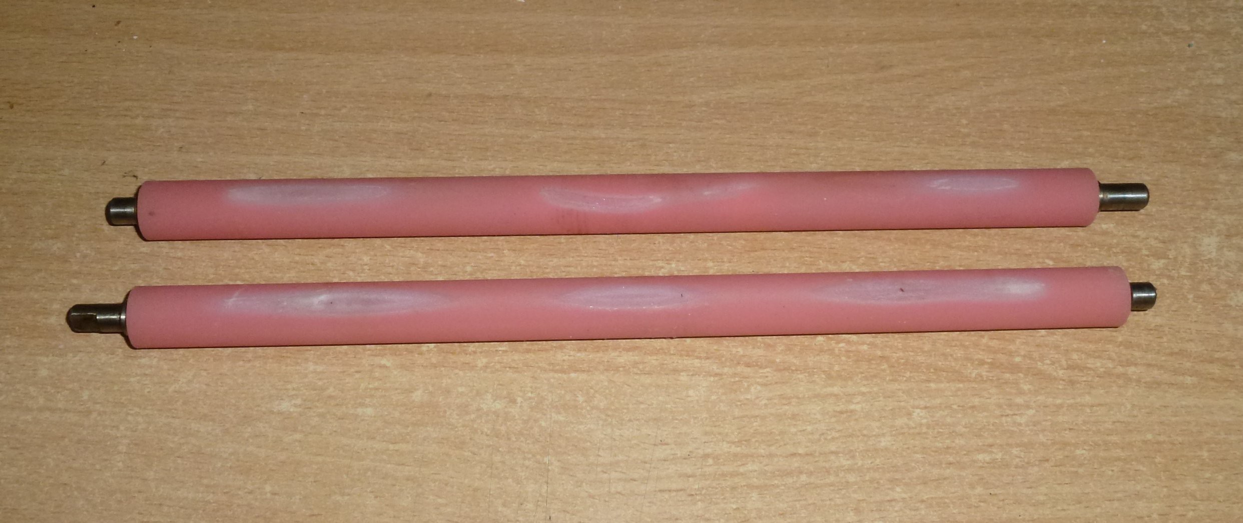
... I burnt the rollers! After this the motor would...
Read more »


Hi, very interested experiences you've shared with us. Thank you. Great step by step experimentation while taking notes on all findings. Could You share the schematic you've used and the code you've tried Please? I intend to use an Arduino Uno Board and a small square (i2C) OLED that shows the initial and/or rising temp along side the set (desired) temp. I will also use the same diode 1N4148 attached on the roller. I will use a rotary encoder only to do the human interaction part. As for controlling a Synchronous AC induction motor it is true what you stated that it is a real pain in the but to properly control the speed without loosing torch. However in my case : My laminator has a 14W motor that has 3 wires. 1 is the common neutral and the other 2 are the forward and reverse. So is still a single phase motor since you only need to power 2 of the wires at any one time. ( N against 1 wire for the forward rotation or N against the other wire for the reverse. My desired setable temperature range would be 165-205 degrees Celsius on my A3 laminator that look like the apache AL13P (and it has metal gear and 4 roller) but it does not have any electronic control board whatsoever. Is just a simple thermostat up to 160 degrees (that has now failed) and a button that does forward and backwards rotation. That is all. So is pretty much bear bones thats why I would like to try a microcontroller. Thank you.