-
This is perfect...
03/20/2019 at 01:15 • 0 commentsI just got a little excited about this again.
Cuda cores for hardware accelerated machine vision, 4 cores of arm cpu, enough ram, gpio, and a raspberry pi camera port. For $99...
-
Purpose.. Contribute!
02/12/2019 at 03:57 • 0 commentsIn the grand scheme of things, this project currently does not have a defined purpose for me right now. Everything I currently have on my plate does not require the population of > 1 board, or is getting hacked together on perf board.
I will be picking this up again as it bothers me to leave it like this, but you will have to be patient.
In the meantime, you could download the existing source files, plop it on any 3D printer, and go to town. I won't hold it against you.
If you need something from me which I forgot to make public, mention my name in Hackchat and I will assist you. If you are in the Tampa area, perhaps you could even borrow the prototype... :)
If you do anything which advances the project, you will be added as a contributor.
Thank you for your interest.
-
Flex
11/03/2018 at 01:01 • 0 commentsMy base is way, way too flexible.
I can get about 1 cm of variation in the end effector position just by lifting a corner. This explains a lot about the issues I've been having.
My nice looking 1/2in oak faced plywood should have been my 3/4in plain Jane MDF apparently.
I have some new 3/4in MDF parked by the door, and this time I'm going to do two layers with cross beams. I need to route out the cable holes through, which in my current 'borrowed shop' situation, requires tools I need to use outside.
It's raining here in Montana, and has been for days. MDF really doesn't like moisture. I'll see if I have a window this weekend, although the forecast says Tuesday. Wish me luck.
<EDIT> No luck, and now it's snowing. So I have cleaned up/moved stuff around my borrowed outdoor wood working area so I should be able to get this cut tomorrow rain or shine, or more likely.. snow.</EDIT>
-
It's not a good morning for Youtube.
10/22/2018 at 15:06 • 0 comments3 minute video. 4 crappy versions. Third try at uploading the last one, 69 minutes and counting to process it. This has not been my day.
Well I guess now at least I can stop focusing on the Prize and get back to more of the fun stuff. :)
-
Cooked servo.
10/22/2018 at 08:42 • 2 commentsI cooked my SG90 mirror arm servo, and I don't have another one just like it. I set the up position too high, so it was stalled the entire time I was figuring out why I lost half my light ring.
It still works, ironically, but it gets really hot now, and moves really slowly. Like 10 seconds per 1/4 rotation slow.
I have the MG90 knockoffs which jitter terribly, and some HS-53 Hitec ones, without arms long enough.
There is some super glue attempting to make the Hitec ones work. Cross your fingers, and I might actually get a video done.
<EDIT>
And I cooked another one. Limits were off by 2.5 degrees. Homing set the servo to 0, which was just outside of the range. Fixed in software now...
</EDIT>
-
New spooling rods
10/21/2018 at 06:58 • 0 commentsTook a significant amount of time, and remade the spooling rods to be accurate in diamater to within .01mm.
That should do it.
-
SPI chaining
10/17/2018 at 18:16 • 0 commentsI want to use the TMC2130 as my drivers, soldered on-board. However, I don't want to consume a CS pin per chip to do it (as I don't have a lot of extra pins on the Pocketbeagle) and I can't figure out how to daisy chain them properly. (Section 4.2 of the PDF) Kind of important.
I also wanted to be able to use the end of that SPI chain to onboard a simple shift register based open drain LED driver chip. That gives me 8 more low current PWM outputs without consuming any more pins. Then, terminate that SPI chain to pins, and I could just keep going...
I don't think I'll be done in time, and actually have a working board the first time around going this route. Time to make a choice. :(
I did find a nice starting point in this ready-made cape for import as a template into Kicad.
As a bonus though, I have discovered UART based chaining with internal step generation and velocity control in the TMC5160 line though. That would be very useful for the mass of steppers I use on the M2. One serial line and power would be all that is needed to run them all. Sweet, but off-topic.
I'm going to slow down and do the Pocketbeagle board right. I'll find something else to assemble.
<EDIT>
The consensus seems to be run the SDO to the SDI of the next driver, and bus the rest of the pins for chaining. I'm past my deadline now though, so still going to slow down and do it right.
</EDIT>
-
PCB.
10/17/2018 at 03:53 • 0 commentsI've had some personal stuff come up which has consumed a few weeks here, and will probably consume a lot more. However, tonight I have some time.
So, I'm designing a board in Kicad for this to run on a Pocketbeagle. If I can pull this off, I should have just enough time to have the parts and board in hand.
Then, I can have this build itself for my entry video. :)
Oh.. have I mentioned I've never actually designed a board in Kicad before? I just downloaded it. I have watched a couple tutorials so this may work..
Most stuff I've done was just deadbugged or hand routed. The 'best' work I've done up to point this was routed in my head, drawn using Gimp, printed on transparencies, and transferred using some spray photoresist. That was an arcade cabinet Jamma 4 board switch.
Wish me luck..
<EDIT>
Well that was confusing. Turns out if you install the kicad-libraries meta-package, it doesn't install the symbols, but marks them as installed. So... no parts. Hours later, removed, purged, installed each package by itself.. now downloading 360mb. That's better.
</EDIT>
-
Milwaukee, Not bad..
10/02/2018 at 08:11 • 0 commentsEverything mostly worked, with a couple show stopping issues along the way.
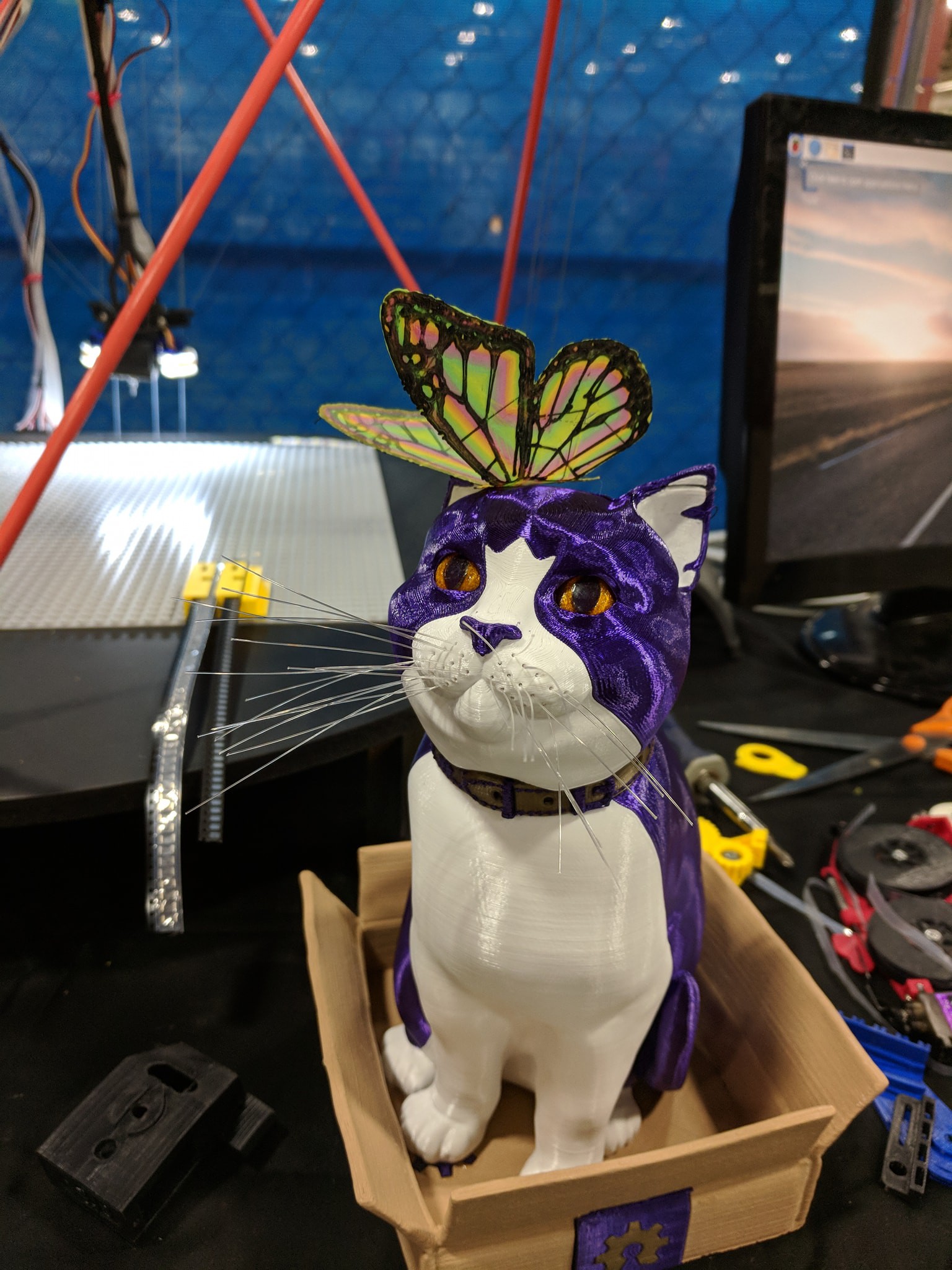
The 3D printer lost extruder 4 just after power up. Don't know why yet. All of my 'ready to go' gcode which used black, in other words... all of them, couldn't be used as a result. cymKwt = Cyan, Yellow, Magenta, Black, White, Clear.
So I improvised and pulled out a 2 layer butterfly model which I could quickly slice, and then added some color codes shifting to avoid the broken extruder, with a Perl script. Probably the best accident I've had happen yet. As long as I cared not for quality.. I could print them in about 2 minutes, and so pretty much every kid got one.
@OshCatPrince was captured here by @pdp7 sporting one.
![]()
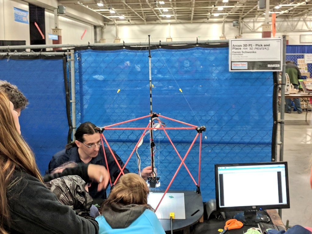
The actual project got a little screwed up in transport, and I lost positioning on the A axis endstop. As the tuning is completely manual at this moment, I never got it back for the duration of the show. Just too much going on for me to concentrate on any task for more than 5 minutes at a time.
I also lost the use of the monitor which had my presentation slideshow on it. That's probably the most sucky thing, as that had my website, repository information, the project point, pretty much everything people needed to know on it.
So I just ended up explaining things a lot, and set it up looking pretty.
![]()
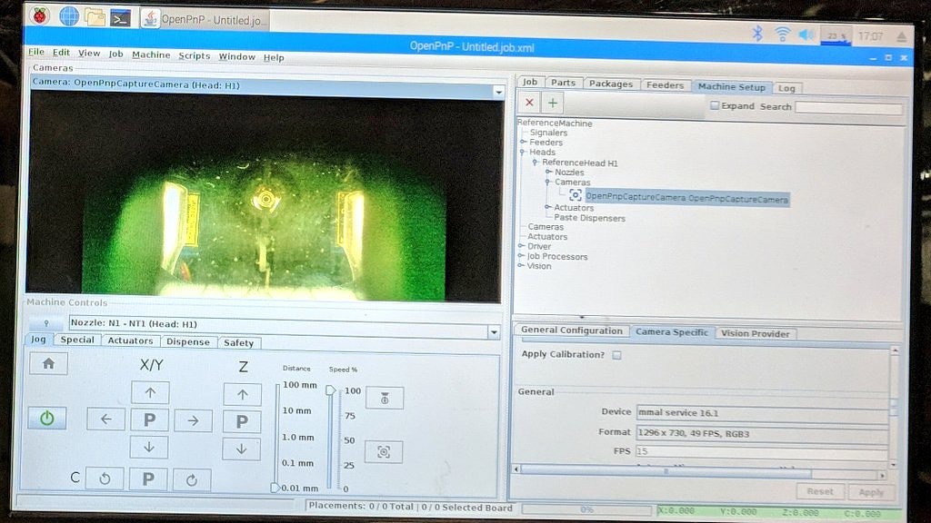
Me, noticing my Pi camera wasn't plugged in..
![]()
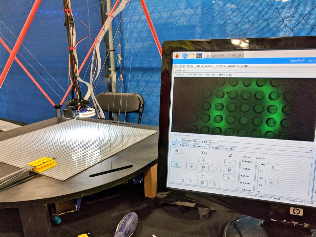
A day of handing it to people and never cleaning the optics = wow.. that's dirty... and green. Resetting the camera fixed the green part.
![]()
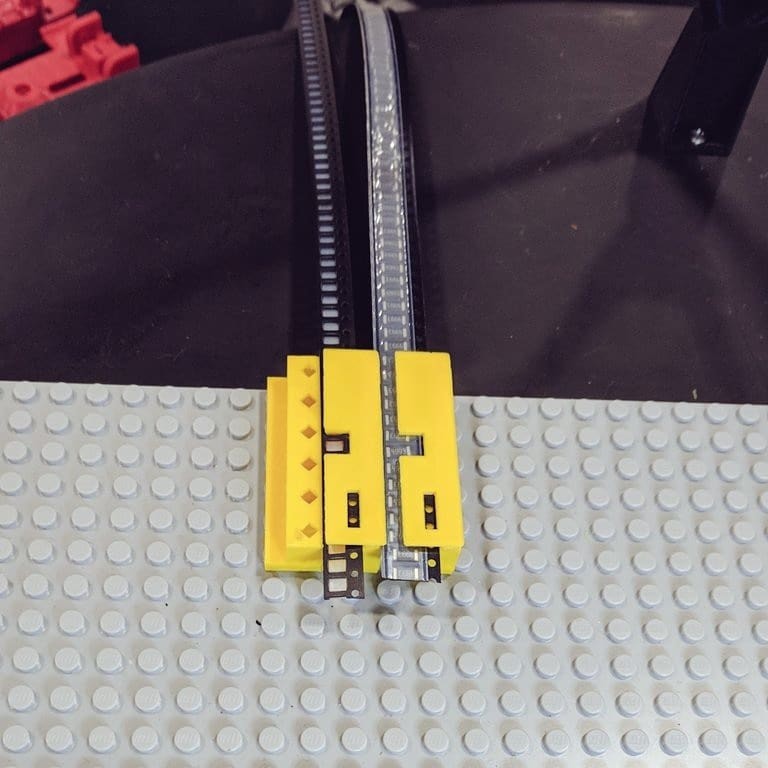
12mm and 8mm tapes, same LEGO mount. The top for the third block was MIA by this point. It probably ended up in the 'failures pile', from which I let people take stuff.
![]()
By this point the batteries in my wireless keyboard were dead and I couldn't locate my spares until after the end, so my exposure would only move in increments of 50 with the mouse. 7,57,107.. The light is pretty bright and the exposure range goes from 1 to 1000. It's about right at 35. Above it was set to 7.
It could have been better, but it certainly could have been worse. I'll take it.
-
Milwaukee here I come
09/29/2018 at 13:59 • 0 commentsAt the Milwaukee Maker Faire today and tomorrow. If you're in the area come on out!
I discovered another issue and solved it. Turns out one of my spooling rods was a slightly different diameter. During the last iteration of rebuilding a schooling rods I replace them with the carbon fiber rods I use for the uprights. I thought I remember measuring them to make sure they were all the same, but I guess not.
That was contributing to the X & Y axis not being at 90° from each other. I entered the correct value for the diameter for the oddball spooling rod and the issue went away. Yay. So I got it all tuned and perfect, and then took it back apart for transport.
So I'm bringing an unfinished project to the Maker Faire, but I got a lot of those so I guess it's okay.
Hope to see you there!
Arcus-3D-P1 - Pick and Place for 3D printers
Open source, mostly 3D printable, lightweight pick and place head for a standard groove mount
 MasterOfNull