MasterOfNull
-
Rotation servo plumbed, mirror servo working.
09/06/2018 at 10:48 • 0 commentsWith the help of Machinekoder, I was able to write a simple component to run the rc servo like an axis via PWM.
I started out with the normal 50Hz update rate, but as the planner is sending all the values in between during the move, that was pretty choppy. I upped the PWM rate to 400Hz and it's much better and that still seems to work for both the analog and digital servo.
However at the higher update rate, the scale for the digital servo is much less linear, but it turns out there is compensation for this built into Machinekit. You just give it a file containing the measured requested and actual positions, and it will interpolate all the values in between. The compensation file can contain up to 256 data points. Right now the file just contains the straight values from 180 to -180, but I think I'm going to use vision to create that file. Then the servo can calibrate itself. Perfect.
The mirror servo did not like being fed the values in between at all. The mass of the lights/mirror made it chatter pretty badly. So I'm going to plumb that up as just a switch, which will pick between sending the angle for 'deploy' and and the angle for 'retract' to the PWM for that. Working on it.
-
Uh, that's not right.
09/05/2018 at 07:04 • 0 commentsGot it all tuned, for the most part. X and Y calibrated and Z was really close. So I started to experiment with how fast I could go. Got it up to 1.5 meters per second. I was happy as a clam, took a nice video and was ready to post it. Uh... wait. Watching the video, it was reading 1.5 meters per second but just timing it over the distance traveled... no. It also had a strangely even tone for a printer using tripod kinematics. it should sound like cats fighting at that speed.
I know what you are thinking. Scale issues, microstep issues... losing steps. Nope. It was 'warping' the paths, rounding corners to make as close to the requested speed as it could.
Now I know the next thing you are thinking. It wasn't the trajectory planner Precision or Quality' setting They are set to an excessively low 0.01 and 0.02.
This also only happens while going fast. And the strangest part of all of this is when it came to a stop it was always exactly where it should be.
I thought perhaps I was at the physical limit for how fast you can twiddle the pins of a DRV8825, but I reduced those values below what they should be, and it did the same thing, at the same speed, so that's not it.
I tried altering the trajectory planner period, the base period, and the real-time thread period also, with no change.
So a couple hours of tuning this and that, and I've come to the realization I'm hitting some limit I haven't hit before. Actual top speed before it starts to cut corners is around 700mm/sec, but I'm barely at half current for my steppers. I had set them low for setup so I could run into endstops and such and not break things, but I never turned them back up! So... I should be able to go a whole lot faster if I can figure this out. Then again, that is actually pretty fast.
Writing this out just made me think of something. Perhaps the PRU has its own base period I need to muck with... Hmmm..
Well, I'm moving on for now and considering this low hanging fruit. 700mm/sec is fast enough.
I have now decided I want to move my endstops out more, which undoes some of my tuning. Working it.
I'll remake the video, with a little less giddiness, when I have it tuned again.
-
Here we go.
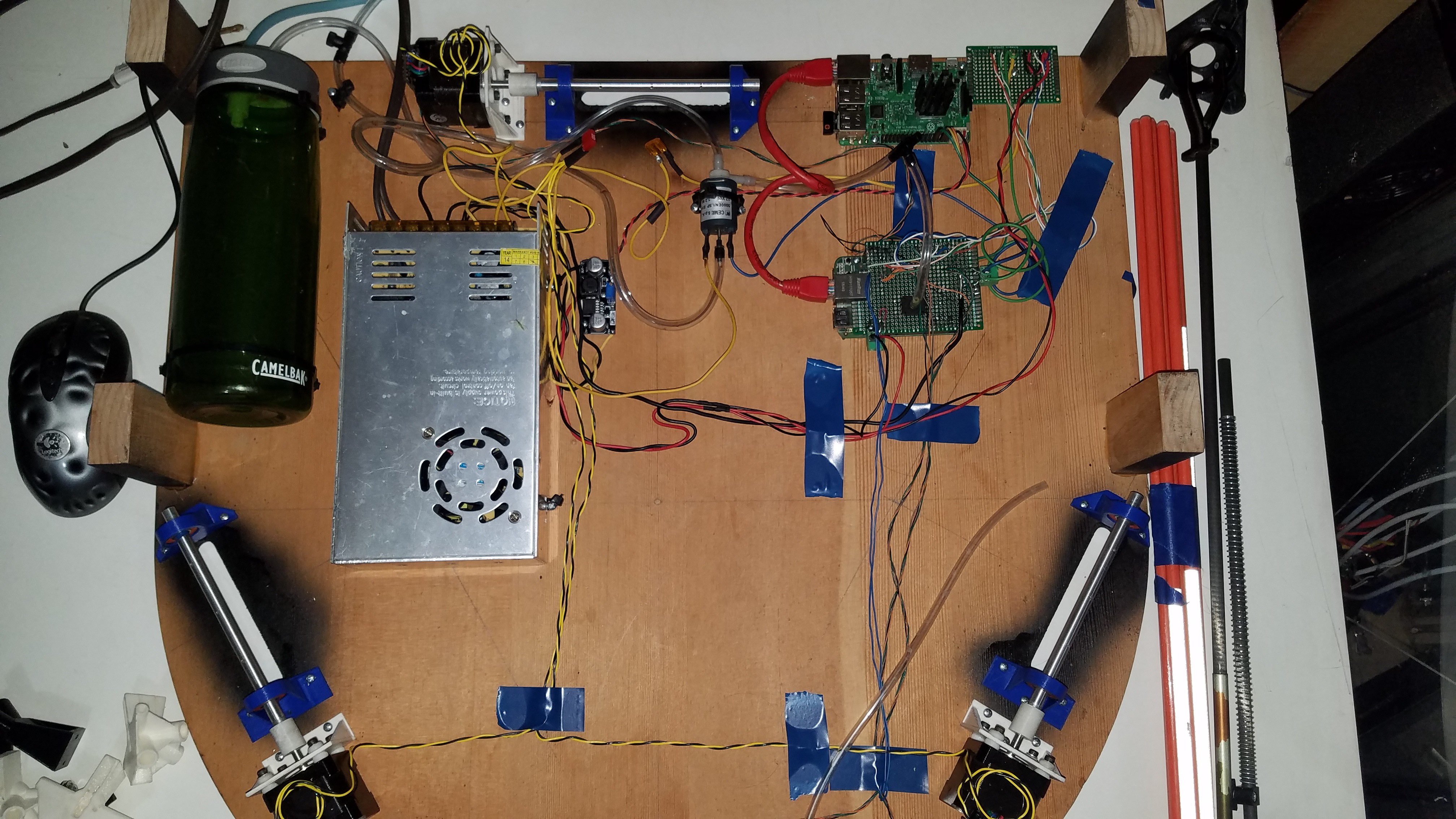
09/03/2018 at 15:01 • 0 commentsIt's finally ready to put everything together. I added a heatsink to the Pi as it was getting unacceptably warm under load.
The motion platform, power, and wiring for my prototype cape for the BBG with vacuum sensing and the required power mostfets (under the board) is done. Perhaps that can be the board this builds.. :)
![]()
Now I can flip it over and assemble the top.
![]()
Labor day. The day you get to labor, on the things you love to do.
EDIT: Day went pretty well.
- Machinekit is mostly plumbed up and homing. I'm finally using the pythonic configs, so that was harder than it sounds. I converted from having 3 endstop channels, to having one wired closed circuit instead. Simpler, and same effect, but had to go dig in the source code of Machinekit to figure out how to make that happen. :P
- I found an error in my math for generating the baseline I use for calibration! My Z deviation is much better now and I know why, which is more important. It's still not dialed in yet, but it's now within a couple mm of the calculated value, instead of *cough* 50mm *cough*.
- Most of the wiring harness above the bed is done, but other than the endstops, not plugged in. I'm not installing the PNP head until I know I'm not going to slam it into the bed.
- Lines got cut, measured, and installed. Of course I forgot to include my endstop beads, and now I can't find them.
I'm headed to town to get some beads. An hour trip for 3 beads, but I just can't accurately calibrate this thing until I have them, and my home positions on each string cease to move around. I'm going to drill and tap them to add set screws this time so I can lock them in place. They moved around a bit when the prototype got packed/unpacked, and I can't have that happening.
X axis is backwards too, so I need to swap two of the joint axis somewhere..
EDIT 2: Of course I then accidentally bought glass beads instead.. So then I spent about 2 hours machining some out of AL, didn't like how they turned out, and then quit having accomplished absolutely nothing.
-
Stronger, is not better.
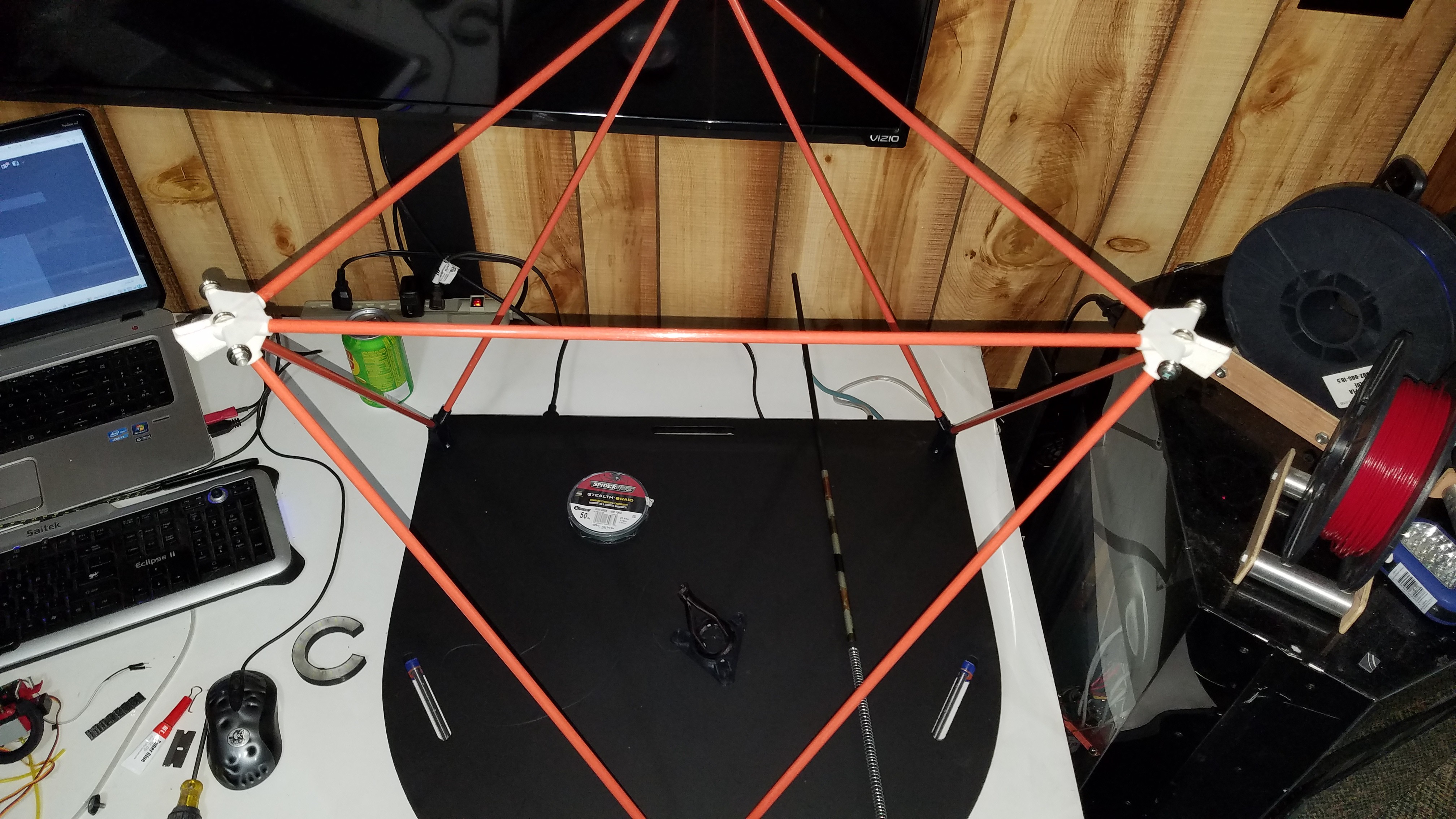
09/03/2018 at 07:03 • 4 commentsFor building up the C1 motion platform this time, I ordered some 110lb test fluorocarbon fishing line. The thought was that the higher break strength would equate to less stretching of the line.
![]()
I was wrong.
I made a quick jig and tested the two. The jig was simply a bar with a pivot with both lines tied at equal lengths from the pivot point. I then put both lines under as much load as I could easily manage and measured the resulting angle. This methodology doesn't give me any actual numbers, but it did give me a clear result.
The 50lb test 'SpiderWire' line I had previously used exhibited less length distortion under load than my brand new 110lb test line.
I then bought some brand new Spiderwire and repeated the test, just to eliminate the possibility of my existing line having been 'stretched to limit' and settling in. Very nearly the same result. The 50lb line still stretched less.
My current theory is that the PTFE coating which is smoothing out the outer contour for the Spiderwire has somehow locked the braid into its current shape, which then serves to help prevent length distortion. The 110lb test line has a much more pronounced braid to it and does not seem to be coated, whereas the 50lb is smooth and slick to be point of creeping if you use a standard fishing line knot. Up until this point I've just mitigated this by putting a drop of super glue on the knot, but there is a special knot you are supposed to use with this stuff to eliminate that issue. I'll have to look it up.
In any case, I'll be using the Spiderwire now. I will need to see if they sell it in higher break strength..
EDIT: Apparently what I called a 'standard fishing line knot', and what I've been using for 40 years, is actually a hangman's knot. It's also used for tying fish hooks apparently but it is by far not the easiest version to use for that. Not that I'm a big fisherman, but growing up in WI this was just one of those things you knew how to do. I can also get air on a snowmobile, and field dress and skin a deer... :)
-
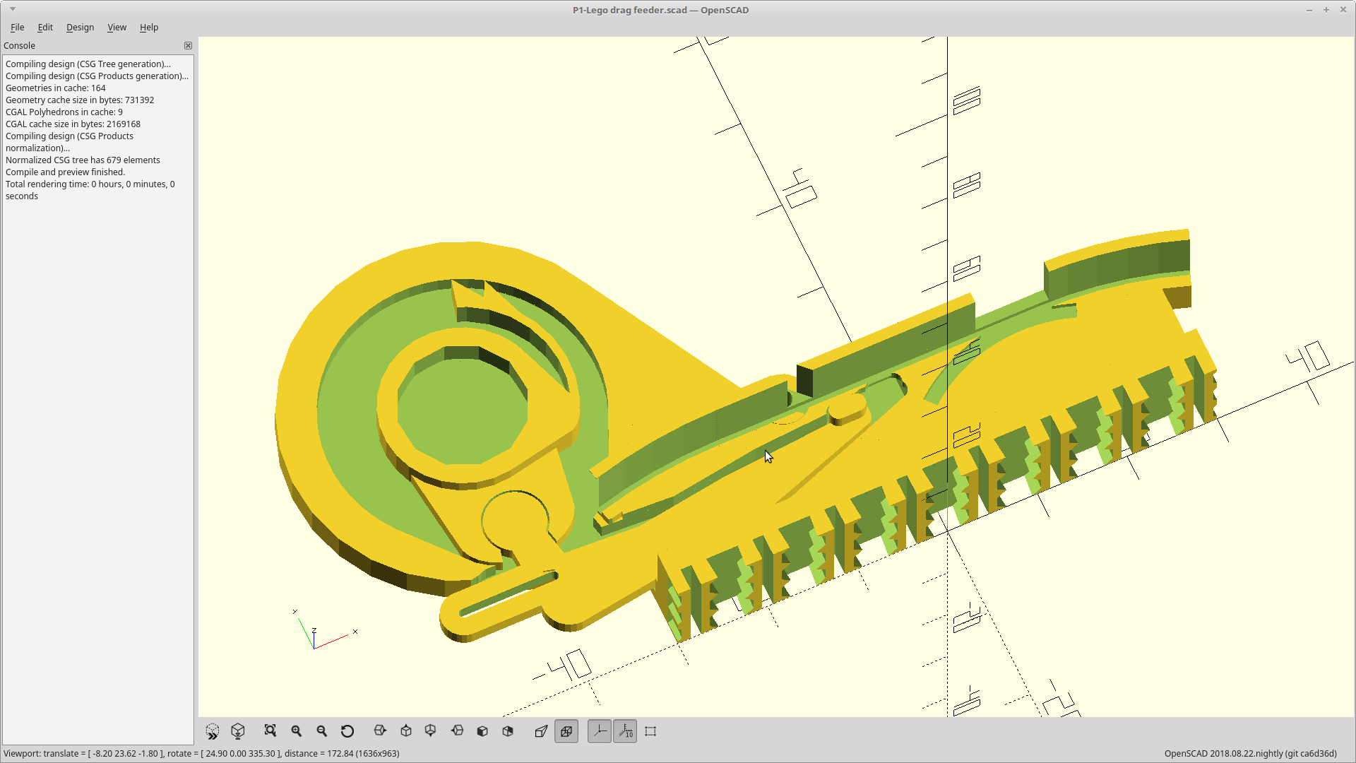
Procrastination pays.
09/02/2018 at 20:20 • 0 commentsI've been avoiding the work of repairing my printer thus far as it's been hard to switch gears.
So I picked another low hanging fruit to work on.
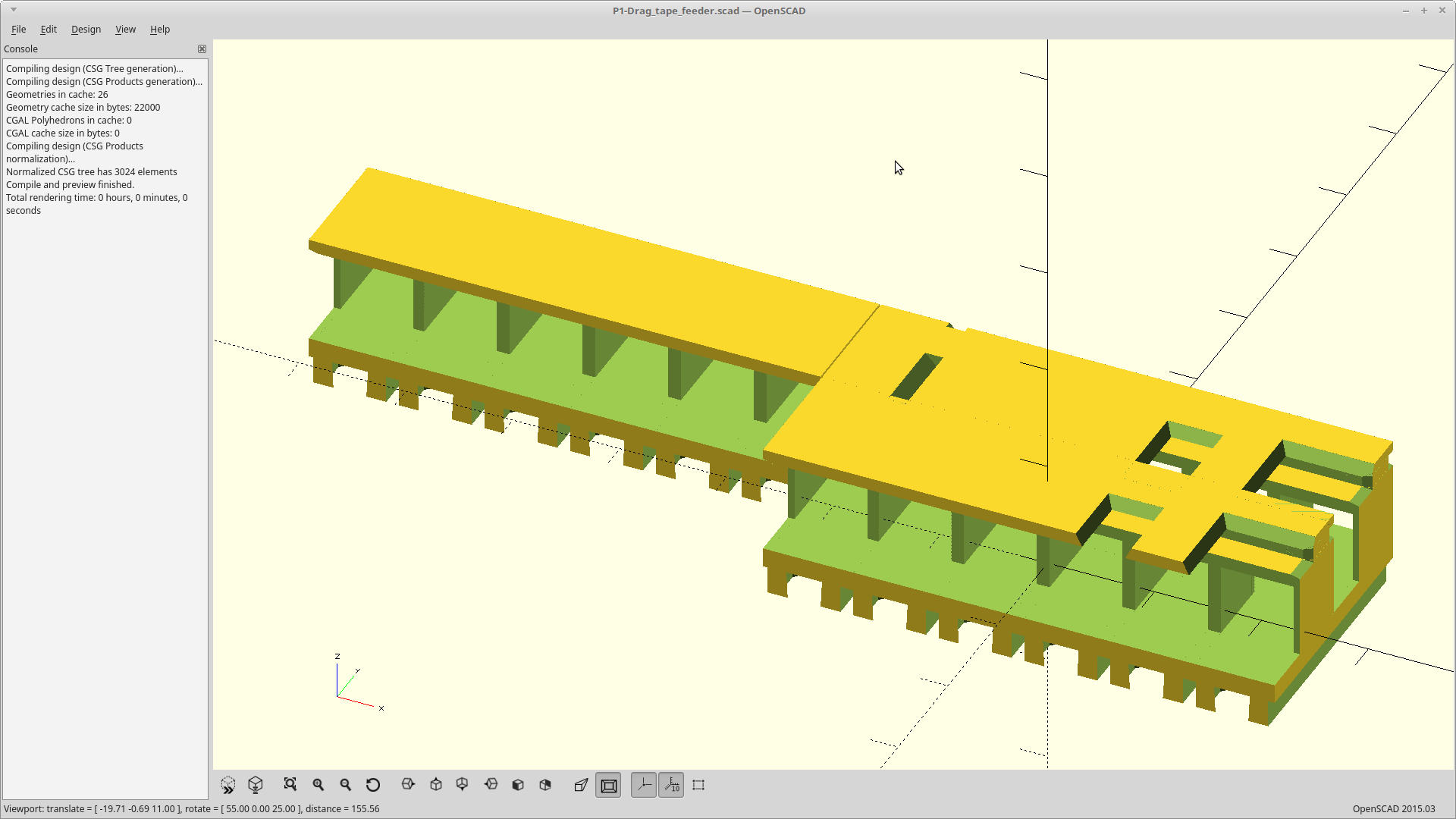
A drag feeder for this project now exists. It is Lego compatible, and in true Lego style, you build it as blocks on a sheet to suit your needs.
Using the Lego sheet means the positions are indexed, so you don't have to recalibrate your part positions every time you change feeders. SMT components come on tape in reels, and are provided in increments of 4mm (8,12,16,24). Lego pin spacing is exactly 8mm. I made the blocks to snap at either full or half spacing. Done.
![]()
It's printed as two parts to avoid needing to have a bridge across the tape edge area and the sucky-ness that entails.
The base is printed on its side which makes it stronger and able to withstand designing in a bending interface, instead of an interference fit, for the Lego pins. It will also tolerate a much wider range of over/under extrusion then also. I had already worked that bit out, so the rest here was pretty easy.
There are a number of cover plates which snap (hopefully) into matching holes on the top of the base for open, covered, fill, feed and peel slot combinations. All are rendered out at 6,12, and 24 Lego pin spacings (8mm) lengths in the Github currently. You can also mix and match the top and base lengths, and so build a 24u length base, with a 12u cover, 6u peel, and 6u pick part if you like.
![]()
It got its own project over here, and the source is up on github: https://hackaday.io/project/160857-p1-lego-compatible-drag-feeder
Now if I could only print it...
-
Meltdown.
09/01/2018 at 10:03 • 0 commentsThere is a bug.
It affects most common distributions of Machinekit. It's not their fault, and the core issue seems to reside within the kernel.
Machinekit is what all of my 3D printers run. The only one which is currently operational without parts being stolen from it... and the one which has printed everything thus far, is the M2.
I got bit by the bug. It's a bad one.
I've been running the printer pretty much non-stop for several months now, so this is not a common thing. In fact when this bug actually occurred the last time about a year ago, I contacted one of the maintainers of Machinekit personally to see if they could use my failure to gather data. Sadly, they were on the road and not available to do so, so I rebooted and moved on.
So enough backstory.
The kernel driven device mapping for the ADC for the Beaglebone can very occasionally, just stop reporting actual values. There is code in the Machinekit distributions designed to detect this occurrence and shut things down.
I don't have it.
I wrote my code to run the M2 before this, and it is complicated by my standards at least, Updating my code to include the safeguard would mean rewriting it. I did not do that. So this is really totally my fault.
Anyway, long story short... My ADC stopped responding. My 80W print head was on and heating at the time.
I was in the room, but did not notice the issue. The print head is water cooled and so it was not until I eventually ran out of water several hours later that it became one. It then promptly ate itself and started to smell funny at which point I shut it down... too late.
It takes about a day to rebuild the print head, but I'm burned out already. I'll be doing that tomorrow.
In the meantime, I did generate a new revision for the Buddha feeder,, started, completed, and subsequently abandoned another version, and then started a new project for a drag feeder. All are now Lego mount.
The drag feeder was really easy comparatively, and probably will be much more useful to the general pubic than the Buddha at this point. I'm rather proud of it. It's totally Lego. Modular building blocks. :)
Unfortunately, I can't print it out, yet, but I have posted the code.
-
Sucky, to success.
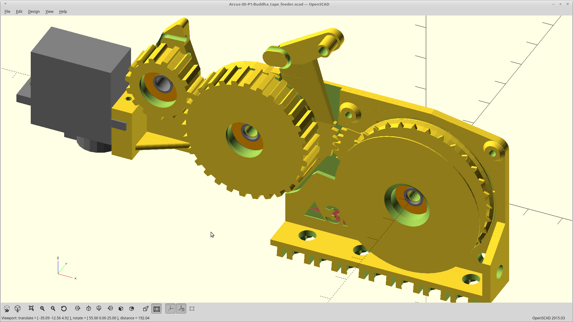
08/31/2018 at 03:16 • 0 commentsThe latest feeder attempt didn't work very well at all.
So I scrapped it and merged the good stuff into the design for the Buddha feeder.
![]()
Updated project log here. Printing now.
-
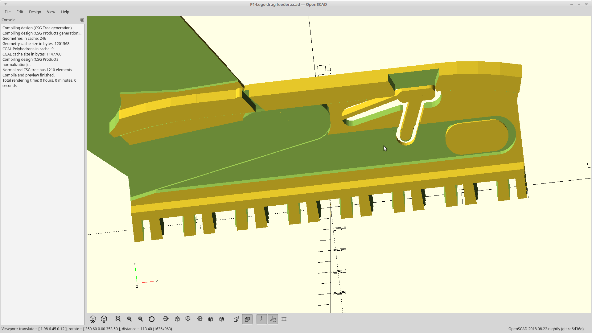
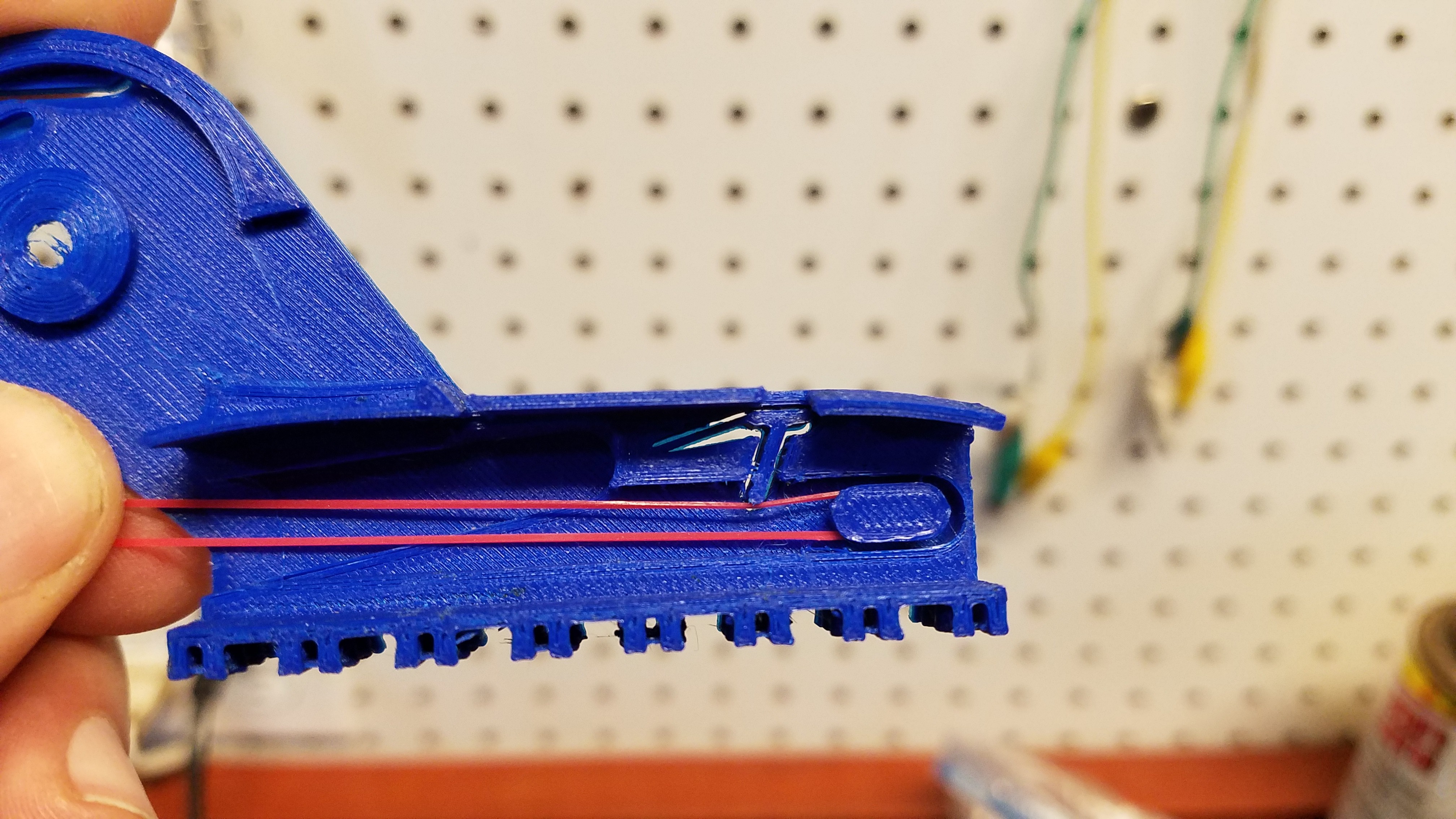
One last look, before I go.
08/29/2018 at 05:58 • 0 commentsThought I would share what the current mechanism for lifting the tape looks like, before it disappears forever into the void where uncommitted code goes to die.
![]()
The thin part was a living hinge, with the top of the T lifting up both the right edge of this tape and left edge of its neighbor.
The bottom of the T came down and intersected with the bands which provide the spring tension for the lever arm, stealing a bit of force to keep the tape held firmly up.
![]()
Alas, I think something which is perfectly at home in a little girl's hair will work better. Goodnight sweet subtraction.
-
Tape feeder, progress.
08/28/2018 at 12:39 • 0 commentsFinished up this iteration of the feeder.
![]()
Way smaller overall, and closer to the build surface.
Smaller bearings, no pins minus the feed pin.
Everything prints flat, no supports, with max 4mm bridging required in one spot, 2mm in one other spot, and 0.8mm everywhere else (the tape feed channel on the back).
Supports the tape from the bottom edges with spring tension at the feed window.
Integrated pinch roller for cover tape removal.Feed area is 20mm high and is currently configured for 12mm deep tapes at widths of 8,12,or 16mm.
Feed lever is 40mm high and vertically actuated. ~14-18mm of travel will advance it.
The last 2mm of lever travel will disengage the feed pin for tape removal.Tape feeds and cover tape is removed on release of the feed lever.
Using the hair braiding bands lets me fine tune the amount of cover tape compression for the feed wheel, and advancement.
60mm total height.
140mm long including the servo. 110mm without it.
11.9mm wide for 12mm spacing.For hardware, it now needs:
- 2 bearings 4x13x5mm. I forget the number atm..
- 1 M3x5mm bolt
- 1 M3x10mm bolt and nut
- 1 M4x10mm bolt and nut (I may need to cut down a 15mm actually, we will see).
- A short bit of piano wire between .8mm and 1.2mm dia. A safety pin would work too.
- A handful of silicone hair braiding bands.
- I'm guessing about 25g of relatively stiff filament and a .3mm nozzle to print it with.
Printing now.
EDIT: The tape channel against the bed was too tight from extrusion bleed-over at the start, and is a pain to clean up.
Also, the Lego snap base needs more bending height, as I inadvertently moved from a flexural fit to an interference one. So it's really hard to get on/off and the tolerances would need to be too tight for mere mortals. In the process of playing with it I snapped off the tape window too.
I think I may need to have deeper tape channels as well, but then I need to add a horizontal force applied to the edge of the tape to keep it against one side. Thinking about that made me remember those little stainless hair clips which invert when you push on them. Wish I had one to play with... I know they are dirt cheap too..
EDIT 2: Picked up a 10 pack of the hair clips at the dollar store. They are a little more than 5mm wide for the back part, and already split into two so I can use a single clip to provide spring tension to both the front and back slots with one part. They are getting added to the design now.
-
Tape feeder, continued.
08/26/2018 at 04:07 • 0 commentsBeen working on the latest incarnation of the tape feeder still.
The most relevant recent changes are:
- Dumped the pen springs and went with 'braiding bands'. I needed more force than one spring would provide, but less than what two would and was spending way too much time trying to get it balanced. With these I can just add another band if I need it instead. They are made from some elastomeric polymer which seems to exhibit no memory, no age related degradation, and they are quite a bit smaller than rubber for the same force. Oh... and they are like $3 for 500 of them.
![]()
- Moved from a pin joint to printed one for the bogey to ratchet interface.
- Moved the spring location, so actuating the bogey now retracts from the tape, and release engages the tape again.
![]()
It has been a lot of work, and I still have more to do.
Arcus-3D-P1 - Pick and Place for 3D printers
Open source, mostly 3D printable, lightweight pick and place head for a standard groove mount