MasterOfNull
-
Not groovy enough.
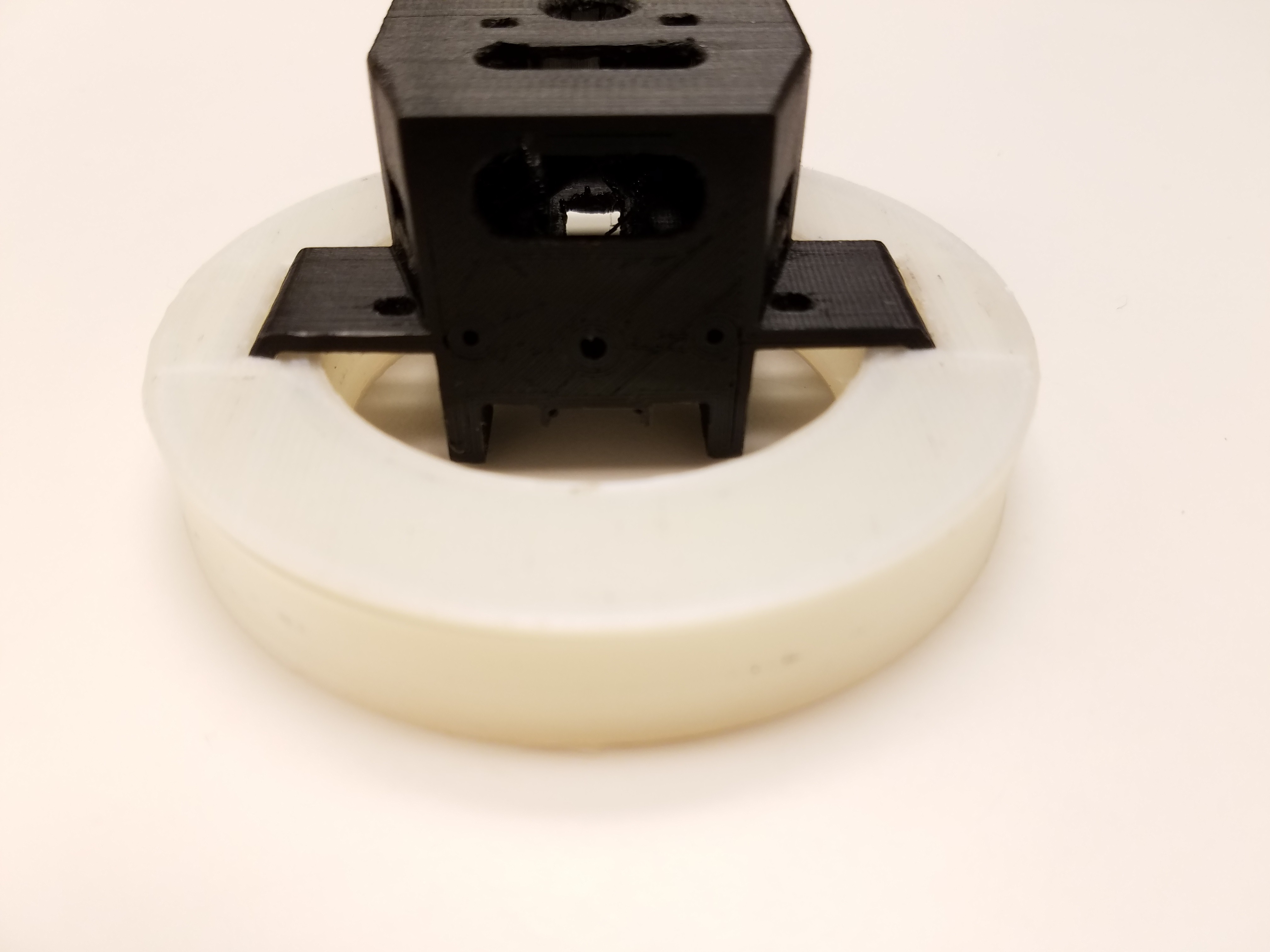
03/14/2018 at 20:09 • 0 commentsAdded the removable groove mount, and I don't like it.
![]()
I'm going to ditch using the three holes for mounting it and use a single central bolt/nut instead.
On a good note, the snap fit for the main light ring works well.
![]()
-
Interchangeable mounting.
03/09/2018 at 01:21 • 0 commentsI've been thinking.. sometimes a dangerous thing.
I think the groove mount should be removable/moveable.
Then people can pick which one of the three mounting positions that makes sense for them, and change out the groove mount for... whatever.
It will likely be a couple grams heavier as I'll need to reinforce each mounting position, but I'm ok with that.
Working on it.
-
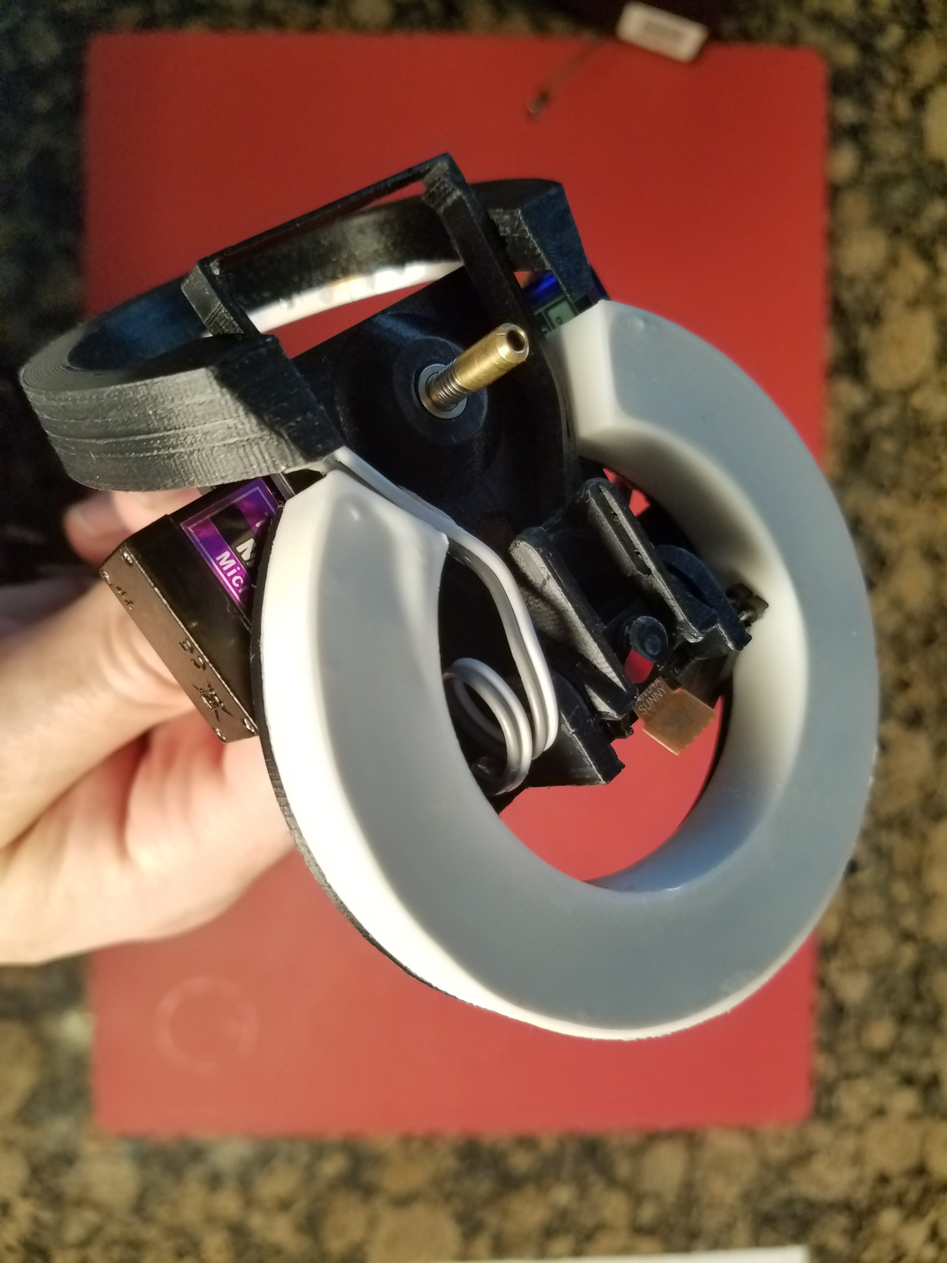
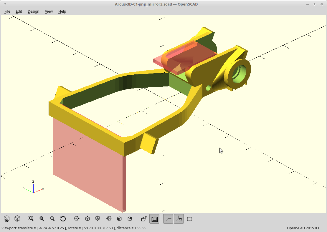
Groovy.
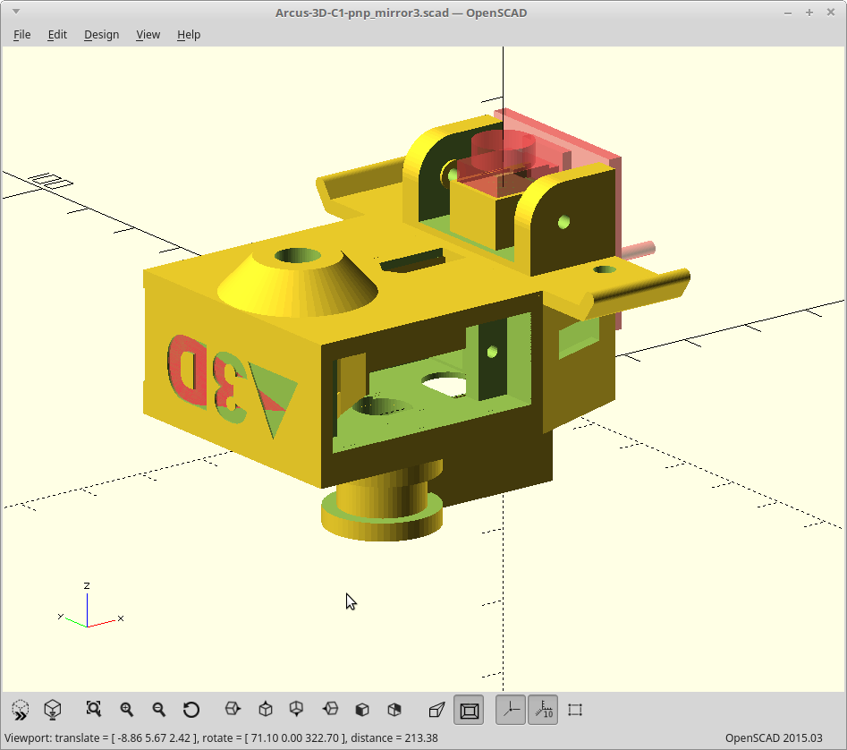
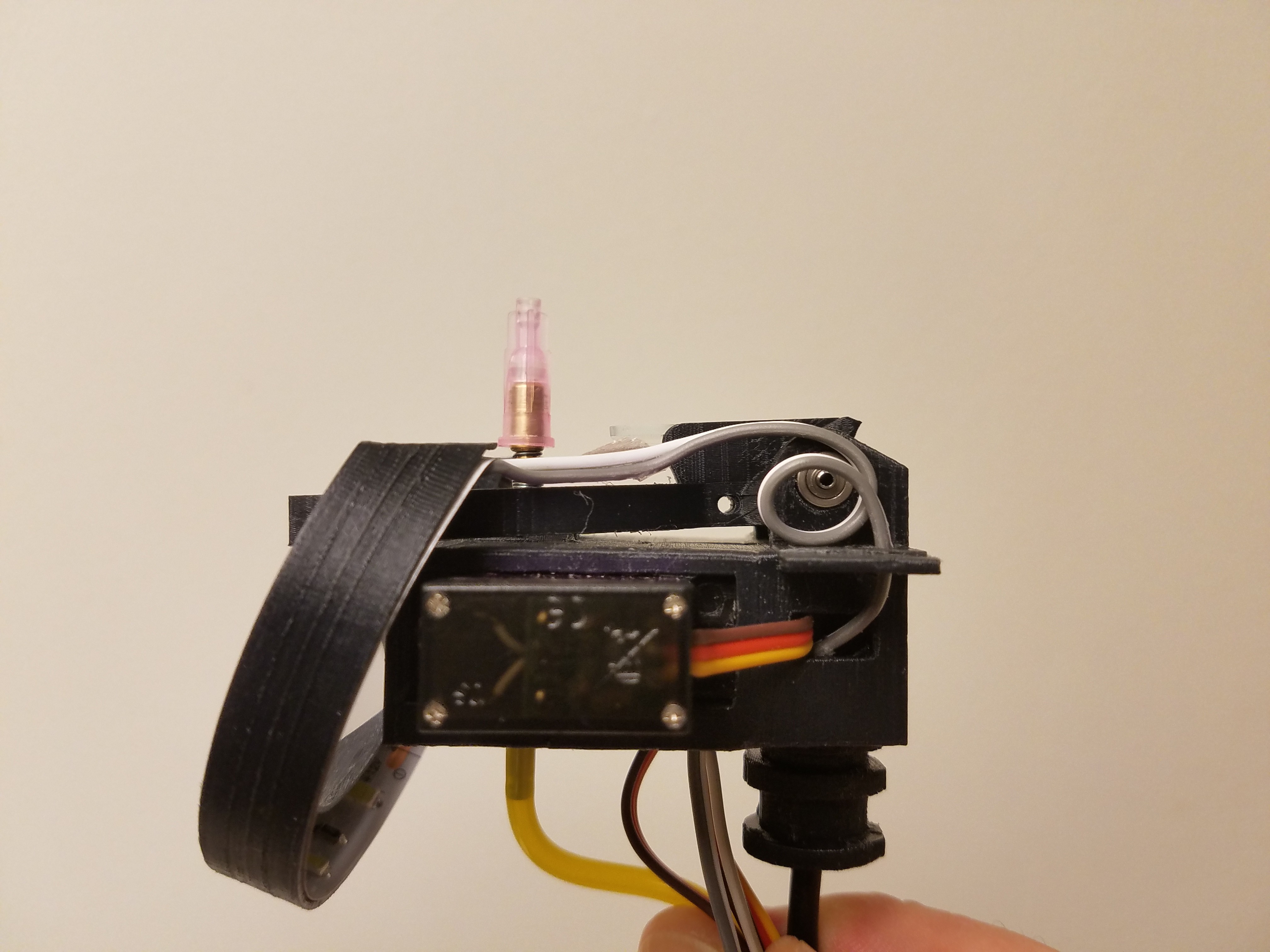
03/07/2018 at 23:10 • 0 commentsMoved the groove mount to the center of mass to see how it looks.
I like it.
- The center of the nozzle is now much closer to the center of the mount, so there will be a lot less torque generated when the nozzle impacts the bed/boards.
- I'm not as nervous about using the base of the nozzle mount to trigger a drag feeder.
- Centered mass is always a good thing.
![]()
I think I'm going to go with that. I'll save the endoscope camera version for others to pursue later.
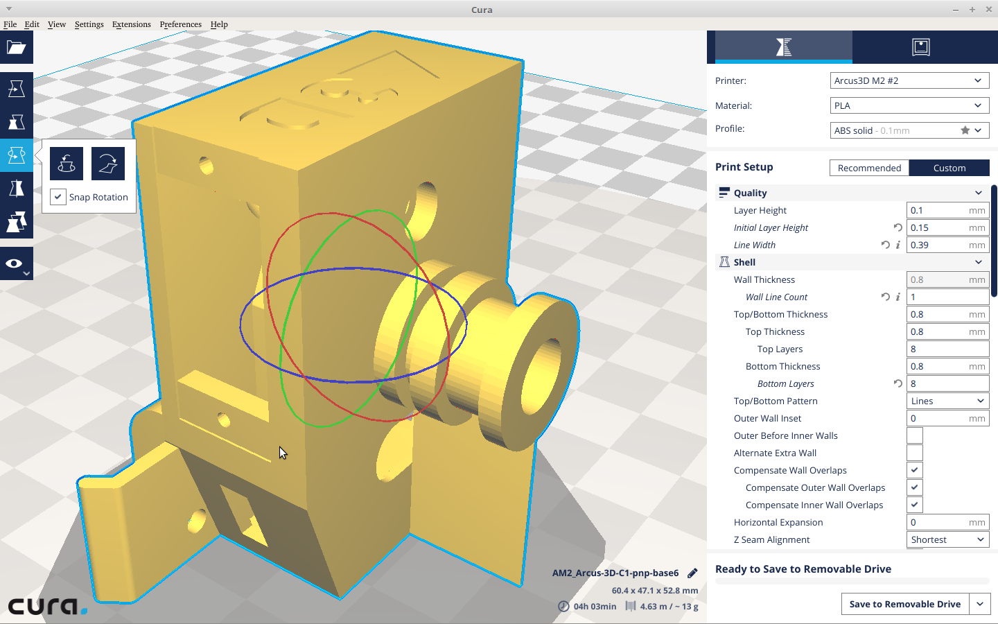
I'll still be printing it standing up though as it will make the groove mount stronger and the bridges are shorter.
![]()
I still have some extra plastic to trim now to lighten things back up, and I want to add some ribs to reinforce the new position.
-
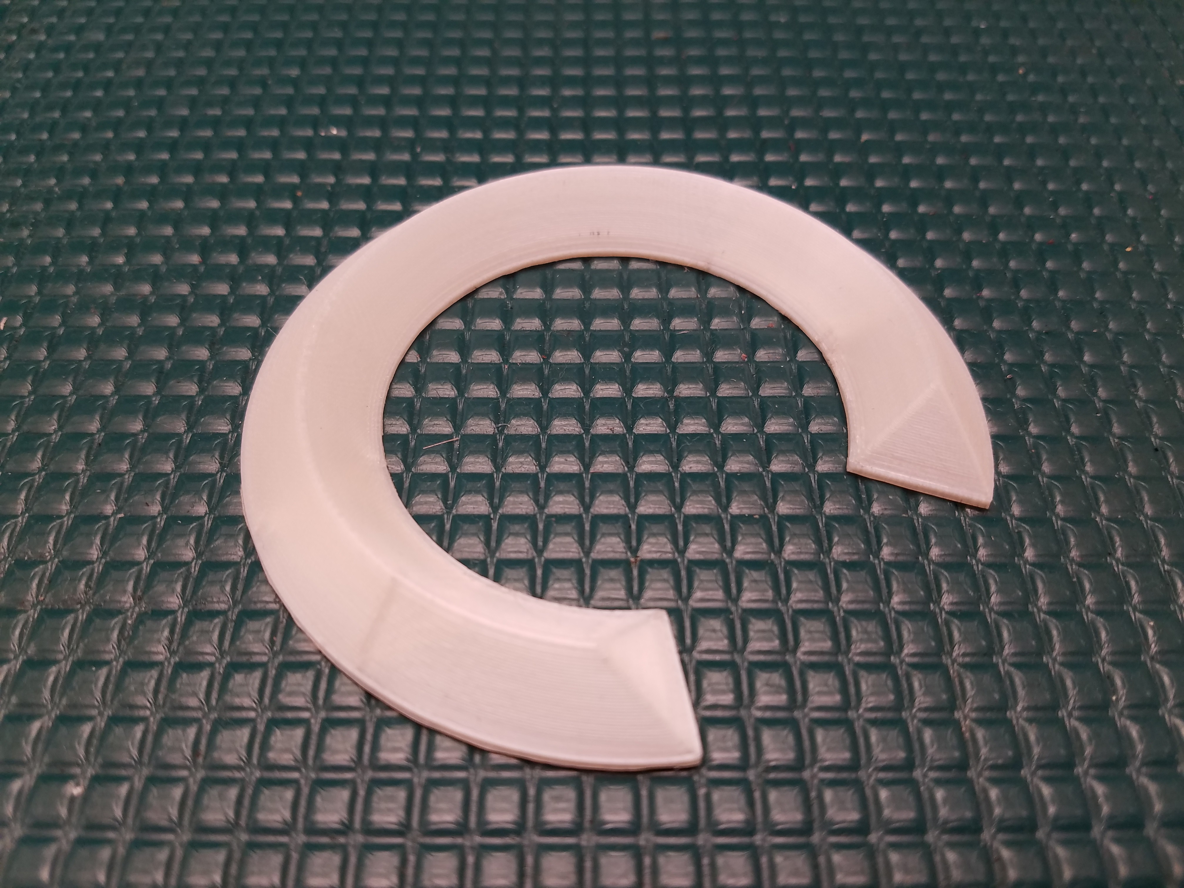
C light not melt..
03/04/2018 at 23:45 • 0 commentsI did a timelapse of the C light being on for 8 minutes.
It got warm, but alas, no melty goodness.
I'm still reprinting it in nylon.
EDIT: Tweaked the mount so its now a real snap fit and reprinted the bottom in nylon. It was too flimsy, so I went back and added a solid bottom layer. This helped greatly, so the reflector part is done.
![]()
The top diffuser portion in nylon was also too flexible which made it prone to separation at the vertical/horizontal wall intersection. I will need to reinforce it. It's only a single nozzle width right now so I'll just step it up to two nozzle widths at the bottom joint, adding to the outside
The diffuser part is nicely translucent though and so I can make it a layer or two thicker. I've also found varying the extrusion width for the lines composing those first few layers gives a nice prismatic effect. :)
-
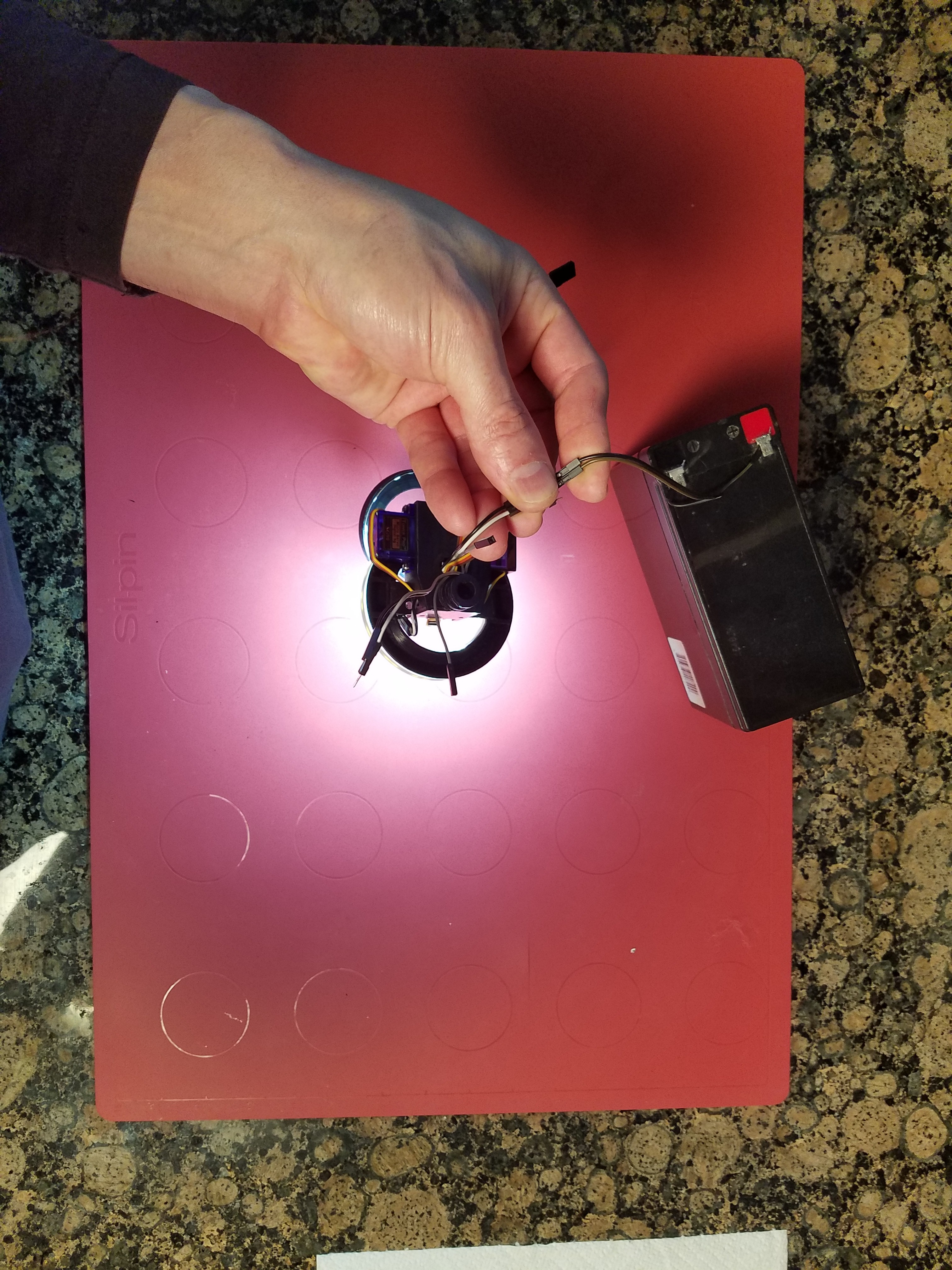
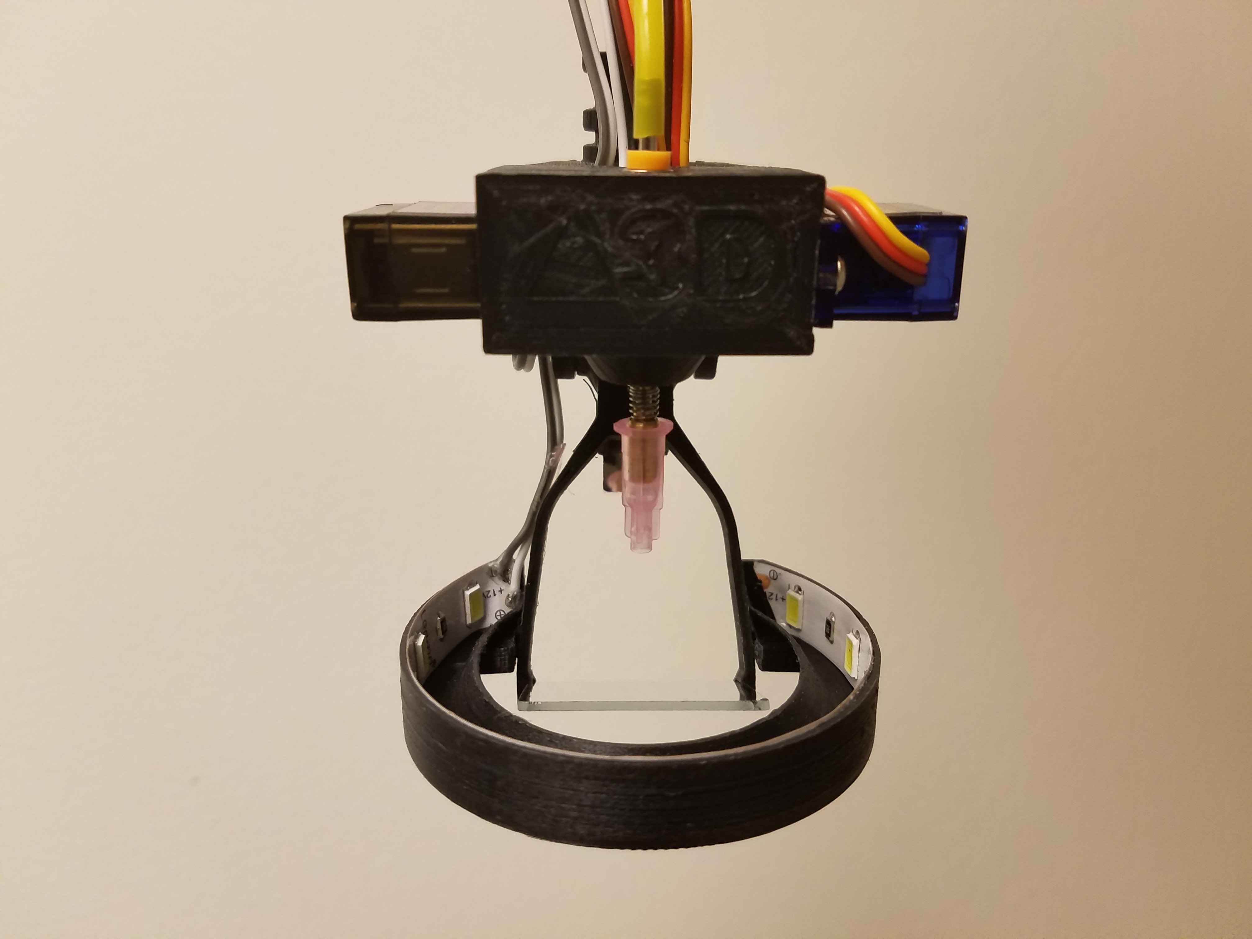
Can you C the light?
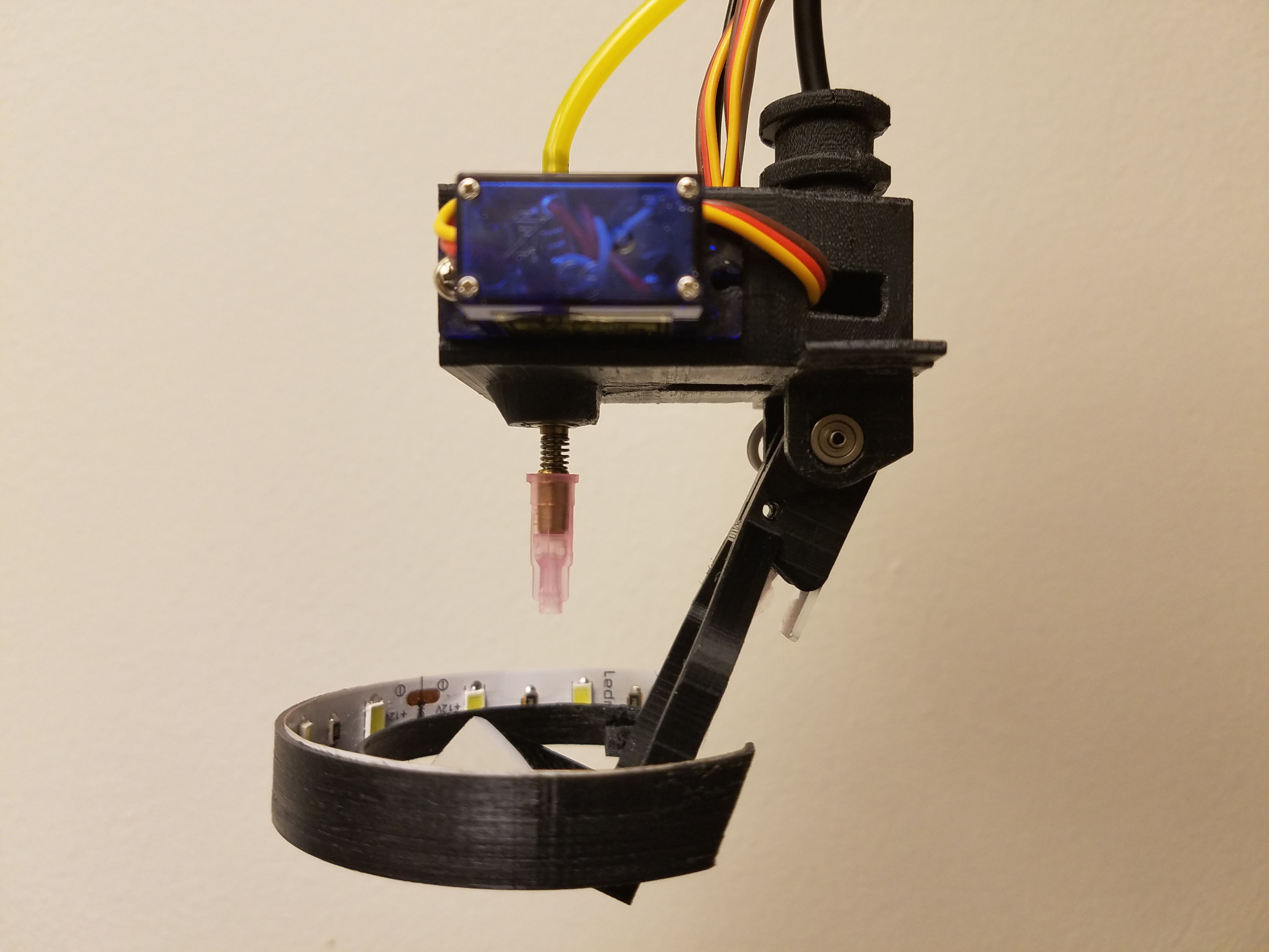
03/03/2018 at 20:34 • 0 commentsI didn't like how the down-facing strip lights were looking, so I modeled and printed a new ring light.
It printed in two pieces. The white part is a PLA box with a .2mm bottom which acts as a diffuser, and there is a black PLA bottom with a foil reflector built in. Each part weighed about 3 grams.
![]()
The warped corner here was from soldering it after sticking it in. Oops.
By turning the LED strips on their side again I was able to fit 7 segments in half the space of the 4 I had planned. This required the reflector on the bottom, which was made with some AL foil and spray glue.
I used these LED strips, the same ones I used for the part lighting. They are 5630 super bright LEDs rated at 22 lumens per LED so I should have a total flux of 462 lumens. Not all of that light is getting out, but it's still 3/4 as bright as aiming them straight down, and the diffuser makes the resulting lighting much more even.
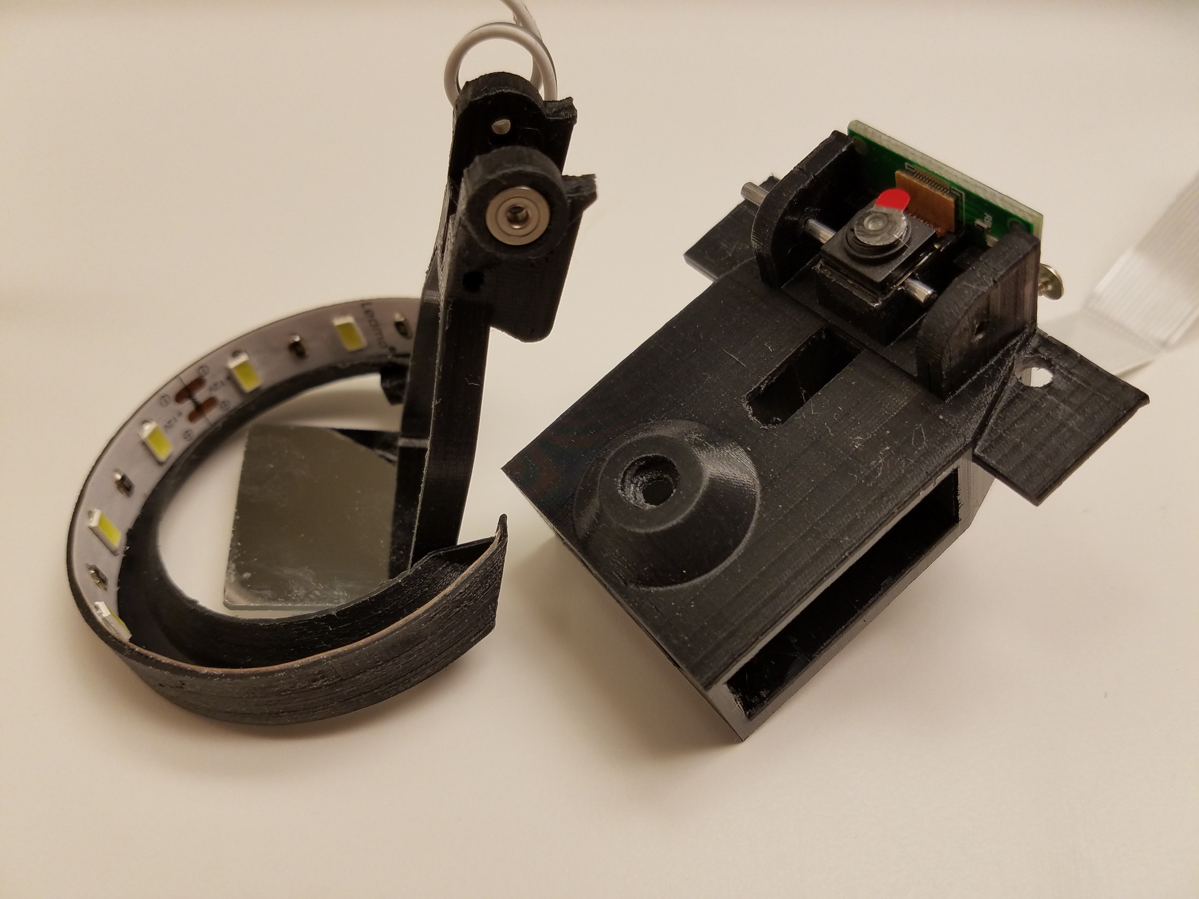
Works well.
![]()
Need to make a new mirror still, and then start on configuring OpenPnP.
-
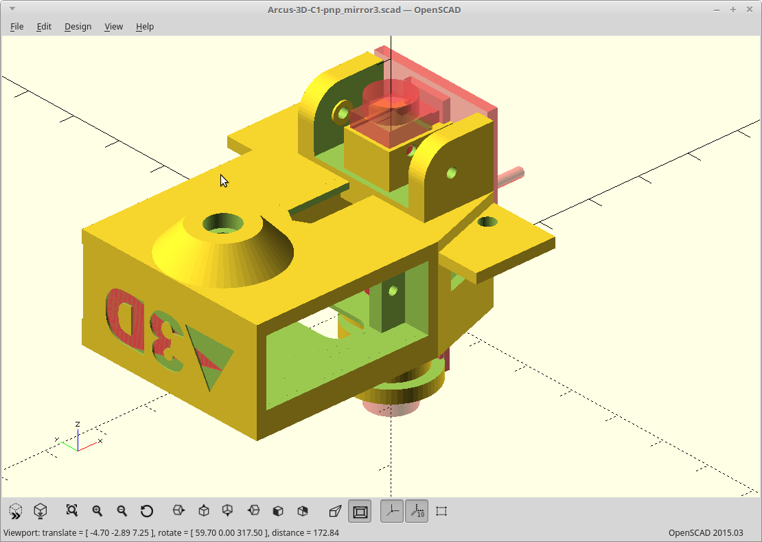
Well, that was easy.
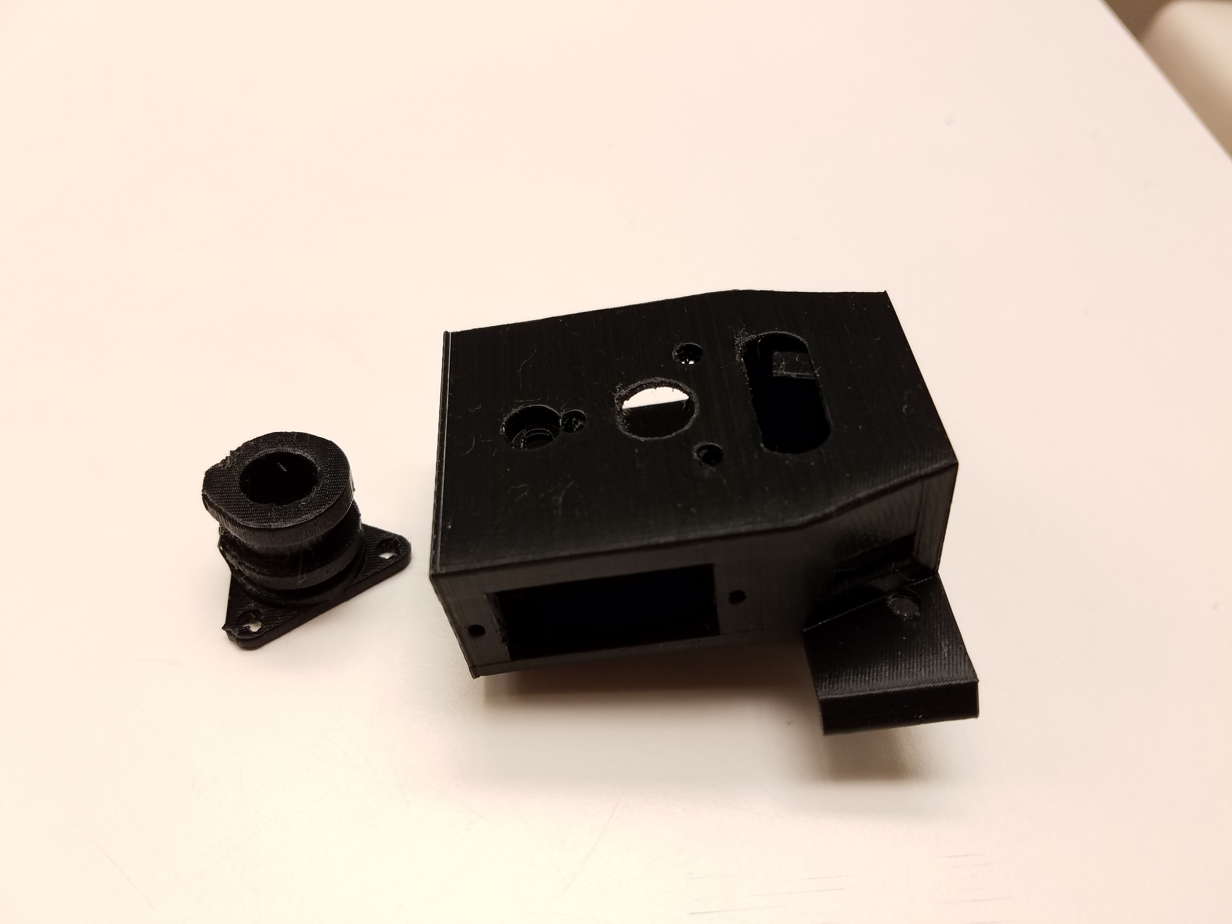
03/02/2018 at 20:00 • 0 commentsThe new Pi camera showed up. I was able to spin the lens with just my fingernails. So.... yeah.
Everything fits. The pocket for the Pi camera was perfect, cable snap clearance was perfect, cable length was perfect, screw holes were perfect, etc. It sure helps to have detailed specifications.
![]()
The bearings got moved to fit in the mirror arm and turned out great. The full length hinge pin passes just under the camera and is a lot easier to remove than the two half pins. I also built two washers into the hinge now which serves to keep the bearings under preload with zero tuning required.
Everything is silky smooth and has zero play. I'm a happy camper.
I need to make a new first mirror as I changed the optics slightly to accommodate the wider Pi camera base. It's a little bigger.
Still have to design/print the strip light baffles. Think really thin, white PLA boxes. They will snap on the black tabs of the body, or so goes the theory.
-
Mirror arm bearings.
03/01/2018 at 18:34 • 0 commentsMoved the bearings into the mirror arm.
![]()
Camera got moved up a bit and the optics adjusted, so if I decide to use a single solid shaft now for the Pi camera version, I could.
![]()
I also decided to go back to a non-adjustable mirror arm stop. I didn't like the idea of snaking a screwdriver along the camera PCB to adjust it. The stop is now printed as a vertical perimeter though so printable accuracy should be really good.
The most critical component positioning is that of the first mirror, so it gets a flat, top surface. Actually, all the optical components mount to either completely vertical or horizontal surfaces for the same reason.
-
Should I move the groove mount?
03/01/2018 at 08:10 • 0 commentsThe groove mount was where it was so the rather long (44mm) endoscope camera body would sit vertically inside it, and the usb cable from it would end up using the path where the filament/bowden tube normally would go.
Now that I have a version with no endoscope, there is really nothing keeping the groove mount where it is. I could center it on the part nozzle, or on the body mass, or whatever.
OpenPnP specifies that for ease of setup you should center your coordinate system on the fiducial camera, but it will take an offset for both the nozzle and the camera so....
Centering the mount on the part nozzle would keep any down-pressure generated from pressing the nozzle into the board/bed from creating uneven forces on the arms for a delta.
Centering the mount on the body mass would be the best for avoiding off center moments during acceleration, and would also allow more usable travel near the perimeters.
Or I could just leave it where it is.
I would have to relocate the wire holes to match and reroute the camera ribbon cable if I do move it.
Thinking about it...
-
How to destroy a Pi camera.
02/28/2018 at 19:41 • 0 commentsI've read many places how you can just turn the Pi camera lens to adjust the focus for near field. There are videos on it. Looks easy.
Got my new Pi camera and proceeded to try the easiest version using two needle nose pliers. That lens wasn't going to move without damaging it.
So I printed the little purpose built bracket which precisely fits the top of the lens so you can turn it without damage, and scraped off most of the glue. Still wasn't moving.
Scraped off all the visible glue holding the lens from turning the best I could and very carefully cleaned as much as I could from the little gap where the threads meet. Yes, there were threads. Still wasn't moving.
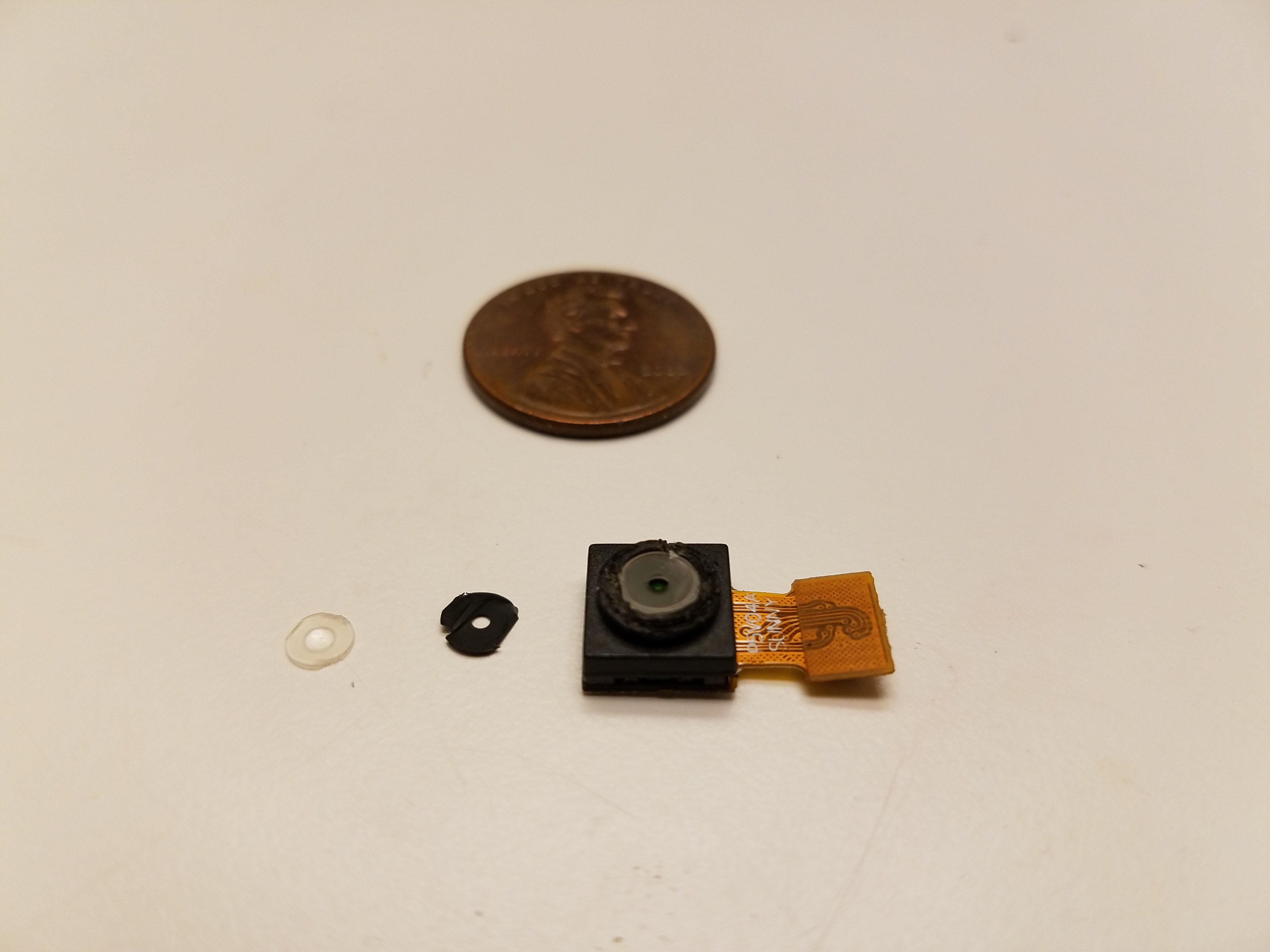
Turned harder. The top of the lens sheared right off. The top bit has joined my missing socks, but miraculously I found the lens and little black spacer inside. So in case you ever wondered what was inside a Pi camera lens, here you go. Two lenses apparently, with a tiny air-gap between them provided by a fiber black washer of sorts.
![]()
You can see impressions left in the top part of the lens from my excessive use of force in trying to budge the threaded bit. The damage on the lower lens and washer was inflicted post-breakage.
Whoever made my Pi camera copy must have used super-glue to fixate the lens, instead of the normal stuff. It's wicked all around the threads and cemented it permanently. It's not going anywhere.
I saved all the important bits still and I think I'll be able to salvage this for normal far focus, so I stopped myself from seeing if the lower lens would pop out. However, without the ability to adjust the focus, this one ceases to be useful for this application.
So I've picked a different, visually distinct, version of the 1.3 Pi camera hoping that I get a different manufacturer and ordered another one. Friday.
Other news
The head and mirror arm model have been updated to mount the Pi camera. It was relatively simple and I was able to keep the endoscope mount. There is a thin bridge below the camera here so it has a precise flat mounting spot, but you can drill that out to fit the endoscope still.
![]()
I'm now messing with the down lighting, converting the ring light to two strip lights of the same type as used in my bottom vision. One less part and the arm can sit lower against the body when retracted.
Having the top LED's of the ring light, in the visual field of the bottom looking camera if you failed to attach a nozzle, was probably a bad idea. I'll squash that one now.
-
Parting (out) is such sweet sorrow.
02/27/2018 at 23:30 • 0 commentsBefore I tear it down to work on the Pi camera version, here are some shots of the latest.
![]()
![]()
![]()
Arcus-3D-P1 - Pick and Place for 3D printers
Open source, mostly 3D printable, lightweight pick and place head for a standard groove mount