-
3D printed prototype
09/07/2015 at 11:27 • 0 commentsFinally, I got around printing the first motor prototype. The frame is here, I still need to find the coil, a 5mm shaft, screws and possibly bearings. I have some small magnets that should do it for the proof of concept.
The stator coil holders were printed in black, that gives the assembled motor a nice 2-color finish.
![]()
![]()
![]()
-
NEMA-17 standard
07/04/2015 at 10:46 • 0 commentsI think the project was a bit too ambitious at first. Allowing all the aspects of the motor to be modified gives a huge amount of freedom, but then building a tool that evaluates performance and generates 3D files for that becomes really complicated...
An intermediate step is to restrict the motor form and allow only some parameters such as motor length, coil diameter and magnet strength to be set by the user. Since the motor form is fixed I decided to adopt a standard: NEMA-17 stepper motor.
NEMA-17 is a very popular motor used on lots of 3D printers, maybe it can be used to actuate an actual 3D printer... probably not, but who knows.
![]()
![]()
The fixation holes are exactly at the same place than the NEMA-17, all parts should be 3D printable (except for magnets, coil, axis, M3 screws and bearings).
I don't know how it will perform though, or if it will melt... No math has been done yet or anything printed at this point.![]()
-
Rethinking the mechanical part
06/21/2015 at 04:06 • 2 commentsI spent some time thinking how to make the building process as easy as possible, after all the motor needs to be printed, colied, assembled, mounted and controlled. The first concept wasn't very user friendly in that sense.
![]() Fig. 1: New concept. Looks like a standard stepper motor.
Fig. 1: New concept. Looks like a standard stepper motor.![]() Fig. 2: Exploded view of all the parts.
Fig. 2: Exploded view of all the parts.![]() Fig. 3: Rotor.
Fig. 3: Rotor.This second concept is all about using off-the-shelf parts. It's controlled like a 2-phase stepper motor when the rotor has magnets on it (synchronous) and when coils are put on the rotor it works as an asynchronous motor.
This makes it easier to control, stepper controllers are really cheap these days and I happen to have some at hand so I won't have to build custom electronics.
For the rotor it's probably better to use something sturdier than a printed axle, a metal rod will do. I decided to use the tiny 635 type ball bearings on either side of the rotor as well. The motor can still be made with only printed parts though.
This is still a concept, I haven't printed anything yet because I don't have access to my printer currently.
-
Motor controller thoughts
05/09/2015 at 00:56 • 0 commentsHaving a motor is nice and all, but for brushless type motors a controller is needed to make them turn. It doesn't have to be something very fancy, an Teensy and some MOSFETs could easily do the work and then some.
Ideally no sensors would be needed as they can break, are noisy and a hassle to mount and use (compared to doing nothing).
In the case of a synchronous motor back-EMF black magic would be possible to turn on the right couple of transistors on the H-bridge (like it's done with hard-drives). The asynchronous motor doesn't need sensors (another advantage for this motor type) as the stator magnetic field has to be non-synchronous relative to the rotor anyway, but the H-bridge transistor commutation still needs to happen...
-
Stator coil winding
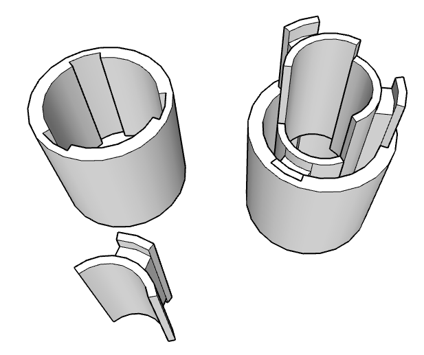
03/24/2015 at 14:31 • 0 commentsWinding the stator and rotor coils will be an annoying part in building such a motor, so this should be made easy. One possible approach is to make the poles insertable, as shown on the picture down below.
![]()
The stator pole supports are not attached to the base, they are printed separately, the stator coil is wound on them (not shown on the picture) and then the poles are inserted inside the base. On the picture 3 poles are shown, but more are possible as well.
3D Printed Parametric Motor
Custom electromechanical motor that can be printed using any 3D printer, some coil, maybe magnets and a controller.
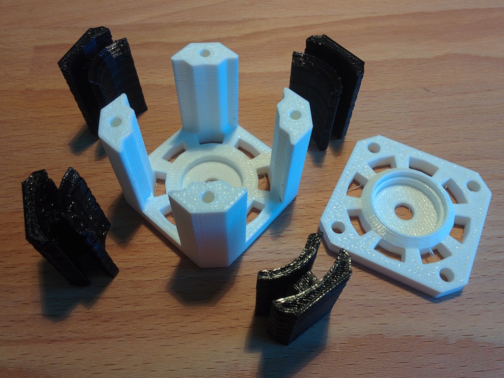

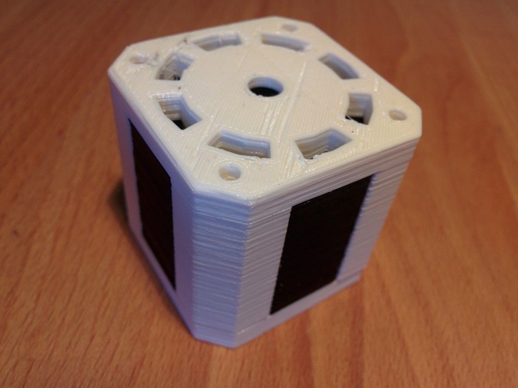
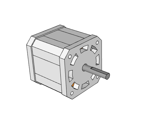
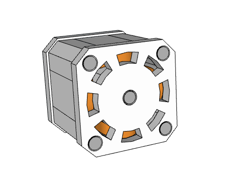
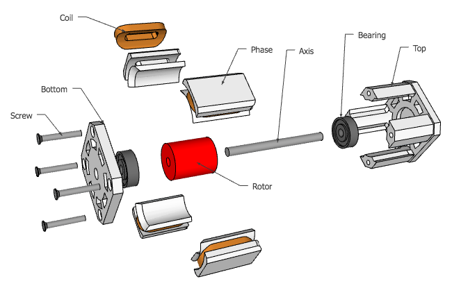
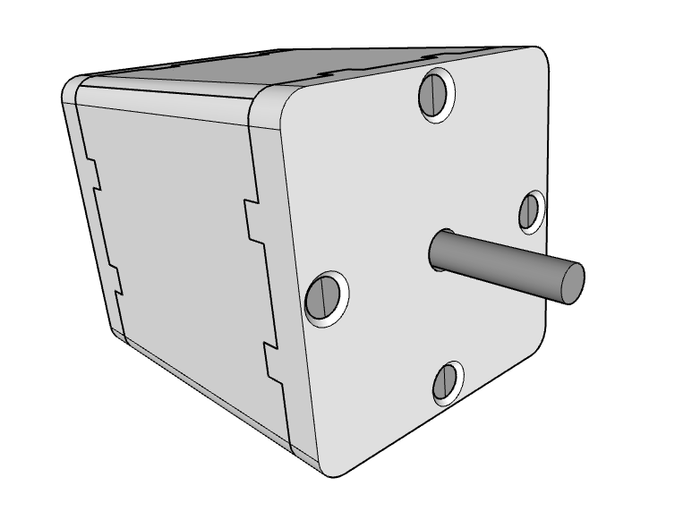 Fig. 1:
 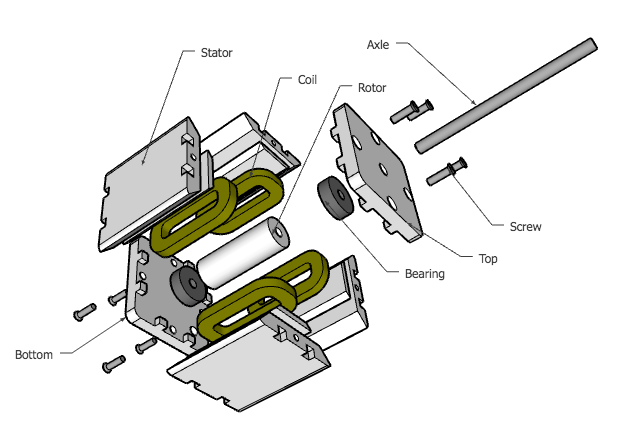 Fig. 2: Exploded view of all the parts.
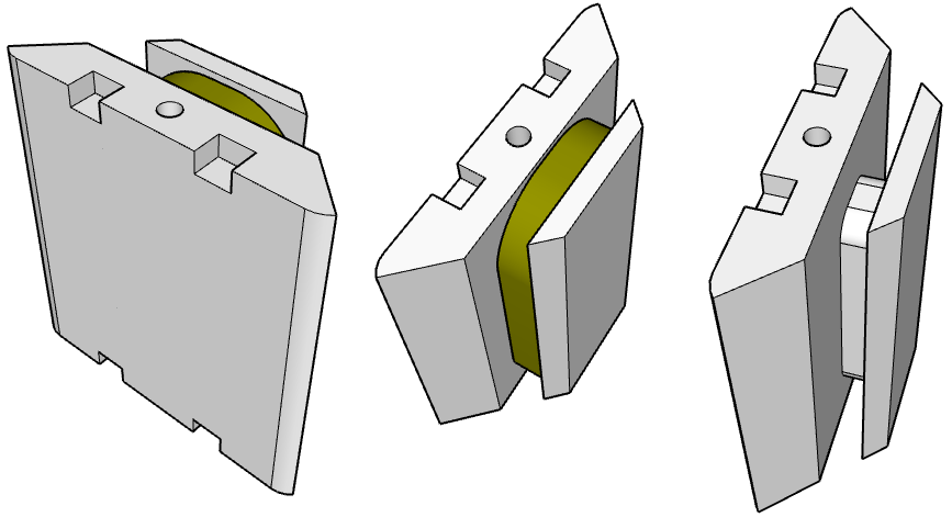 Fig. 3: Rotor.