 O. Alan Jones
-
1Step 1
Build 5 volt regulated power supply:
For the complete circuit I will be using the following components:
- 78L05 voltage regulator (TO-92)
- PIC16F628A microcontroller
- red led
- 1 - 470 ohm 1/4 watt resisitors
- 10k ohm resistor, 1/4 watt
- 0.33 uF ceramic capacitor
- 0.01 uF ceramic capacitor
- 0.1 uF ceramic capacitor
- hookup wires
- 9 volt battery
- 9 volt plastic battery holder with wires
- 6 pin male header
- 18 pin IC socket
I will use the 78L05 voltage regulator to build the 5 volt power supply.
![]()
According to the data sheet this is what the regulator portion of the circuit will look like:
![]()
-
2Step 2
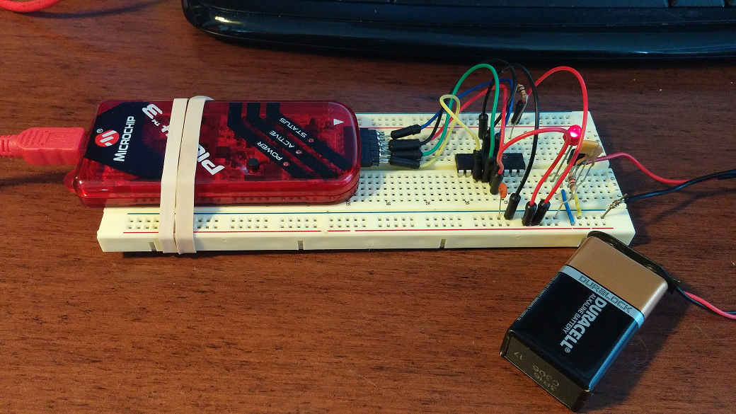
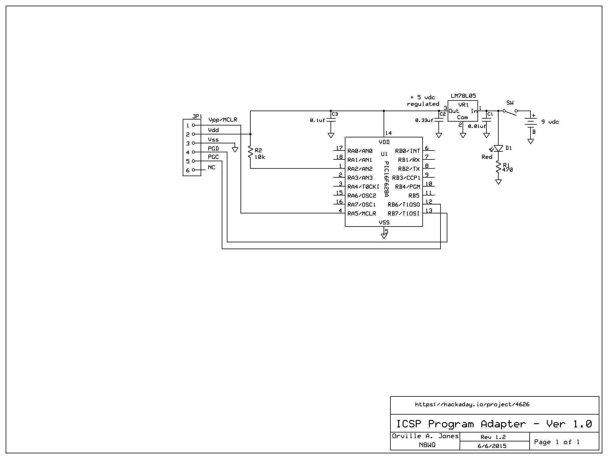
Build ICSP program adapter on breadboard:
![]()
Here is the schematic to my breadboard ICSP Program Adapter. I uploaded the correct schematic.
![]()
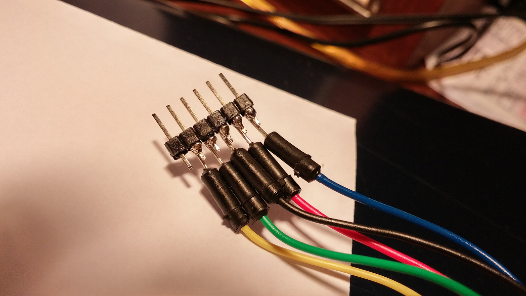
I created my own ICSP cable by very carefully soldering hook up wire to a 6 pin male header.
![]()
I chose to color code my wires like this: Blue = Vpp/MCLR, Red = Vdd, Black = Vss (GND), Green = PGD, Yellow = PGC.
Pin 6 is not connected in our circuit. So the Blue wire, pin 1, will go to the white arrow on the PICkit3.
-
3Step 3
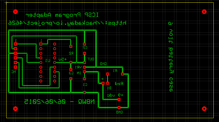
Layout and create pcb for ICSP Program Adapter:
For this part of the project I used ExpressPCB software to layout my ICSP Program Adapter. Then I used Robot Room Copper Connection to flip the pcb design so I could create a single layer pcb with the copper on the bottom.
![]()
I transferred the toner to the copper pcb using a laser printer and color paper. I then transferred the toner to the copper pcb with a laminator. Next I etched the pcb with a mixture of one part muriatic acid to two parts of hydrogen peroxide.
-
4Step 4
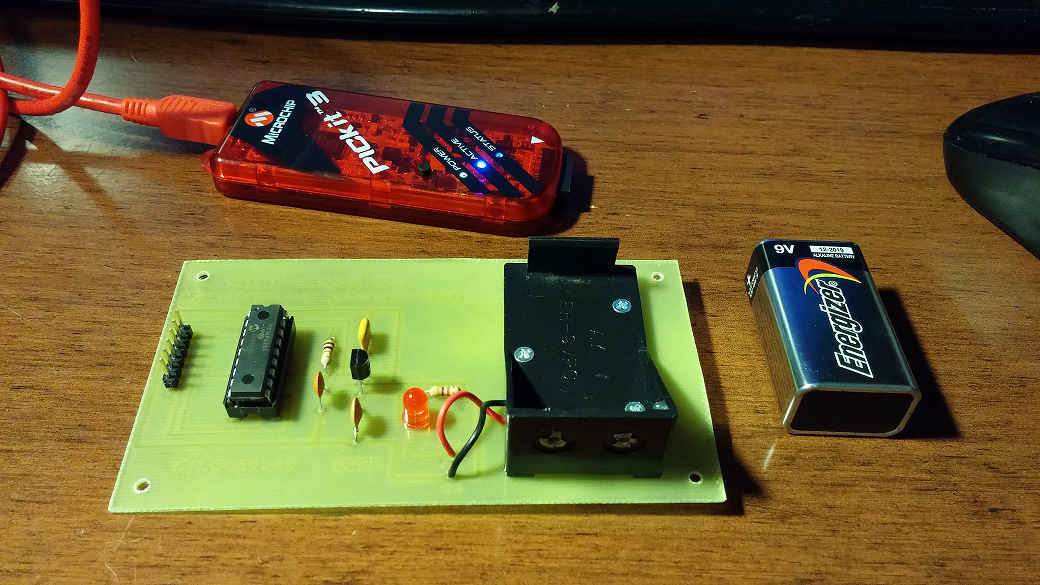
Populate board and solder components:
I just finished testing the Program Adapter out and it is working great!
![]()
My next version of this board will have the 18 pin ZIF socket installed. The red LED is used to indicate the 9 volt power supply is on. My next board will also have a switch to turn the battery on and off. It is amazing how simple the ICSP Program Adapter circuit is.
-
5Step 5
Build oscillator stage on development board:
(a work in progress...)
Note: See PIC16F627A/628A/648A Data Sheet, Table 14-2: Capacitor Selection for Crystal Oscillator.
I will be using the XT (crystal oscillator) mode. At a frequency of 4 MHz, capacitors C1 and C2 can be 15 to 30pf. I have 24pf ceramic capacitors in my parts supply so that is the value I will be using. You will note that in the components list I listed 22pf. Almost all the documentation I am reading shows 22pf caps in the oscillator circuit. When in doubt always read the data sheet! :)
BTW, I highly encourage you to buy a LCR meter (inductance/capacitance/resistance) if you can. I always measure capacitors,resistors, and inductors I am using to see how close they are to specs. It will save you some troubleshooting later!
Open Source PIC Development Board for Newbies
This project is about learning how to use PIC microcontrollers. We will take what we learn and build an application for Amateur Radio.
Discussions
Become a Hackaday.io Member
Create an account to leave a comment. Already have an account? Log In.
Yesterday morning I successfully troubleshot my homebrewed ICSP program adapter and I learned how to use the stand alone PICkit 3 Programmer software (not MPLAB).
Are you sure? yes | no
I like to get up on Saturday morning and put my ideas on paper while I drink my first cup of coffee. My mind is always the clearest in the morning--before anyone else in my household is up. This morning I am reading the data sheet for the PIC16F628A and making notes for my project.
Are you sure? yes | no