marcelclaro
-
walking...
06/07/2015 at 21:32 • 0 commentsFirst, Thanks all for the support and the blog mention.
I was out of home in the last weeks, and I will be busy for the next two weeks also. So, I had a little progress and few opportunities to answer the comments (the bad and good ones).
The hardware still running, but, since I'm out of home most of time, I did few measuments. Because of that, I think it will be important to make the portable hardware soon as possible. However, the Lightblue Blue still at customs.
Within the small data that I already have, I tried some regression algorithms, one of the best is the Self-organizing map. I will study it and try to use this algorithm in the next weeks to do some previsions and try to see if it works. As a self-leaning algorithm the previsions would become better as the time advances. Until now I used orange to do the data visualization and regressions.
I plan to do some changes in the next hardware versions. It will be portable and as I'm not totally happy with the noise level, I will try to improve it. First, I will try to put the photodiode and the ADC in the same board without cables, and with a metalic shield.
I also brought some laser diodes. While the LED has emissions with a width of 150nm, the laser diode has only 5-10nm. I brought 650, 808 and 1610nm laser diodes. With a narrow emission, I think it will be more selective to the glucose (and 1610nm is better than 1550nm in theory)
-
Data mining
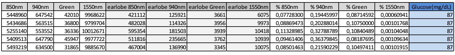
05/23/2015 at 20:01 • 0 commentsToday I start to colect the raw data with 5s integration time.
In the first columns I read the ambient+LED emission without any absorber, next with absorber (the earlobe), next the calculated transmission and finally the glucose level by a Optium Xceed glucometer.
![]()
I did 5 measurements in 5 differentes earlobe position (I always need to take of from the earlobe to measure the values without earlobe).
I plan to do it for the next days while I design a definitive and portable version of this hardware. As I win a LightBlue Bean, is a good idea to use it to get the data from my phone.
-
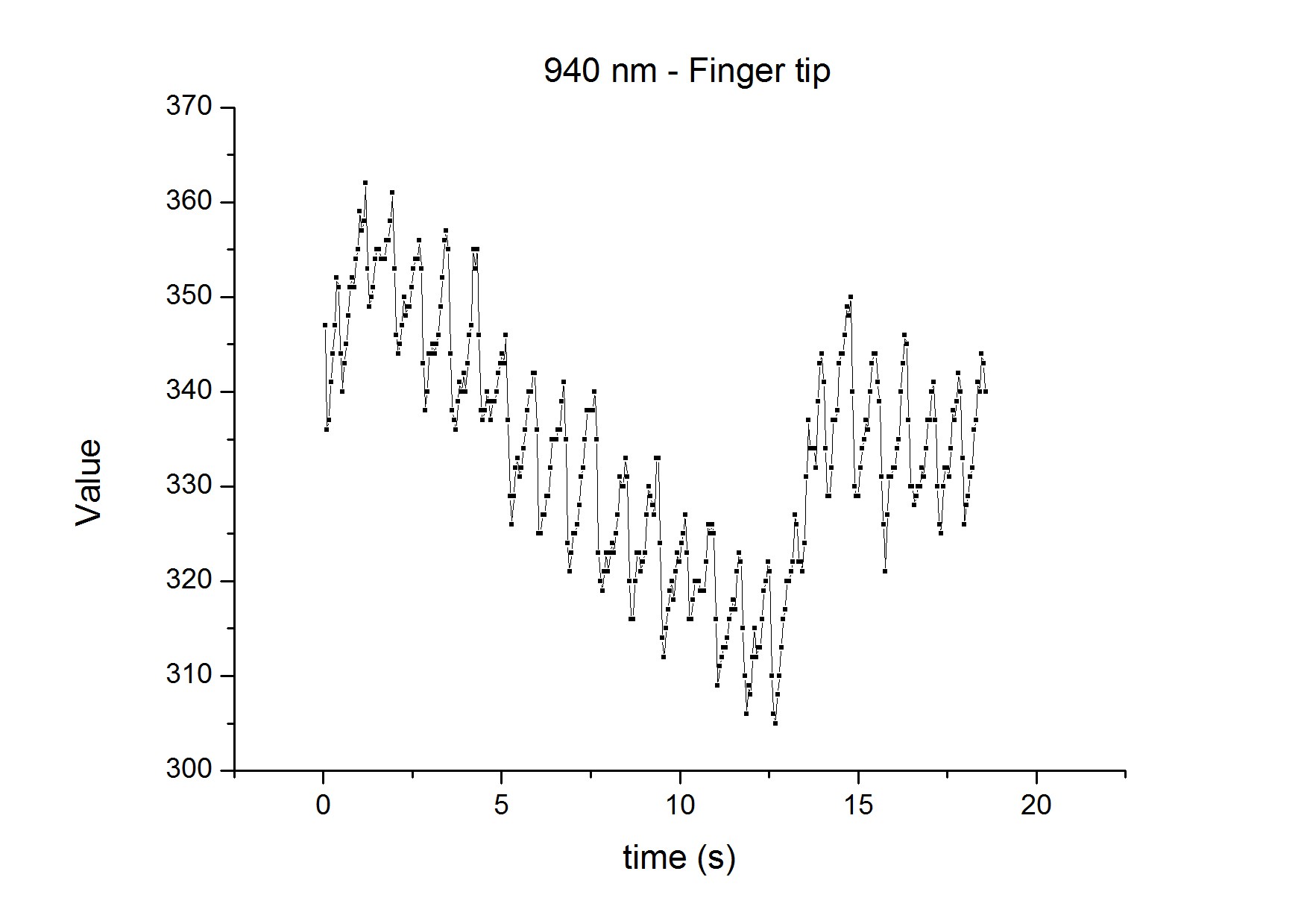
Checking pulse oscillations
05/23/2015 at 19:44 • 0 commentsHere is a check for pulse detection in 940nm when a put the Diode+LED through finger tip.
As you can see it's work fine!
![]()
-
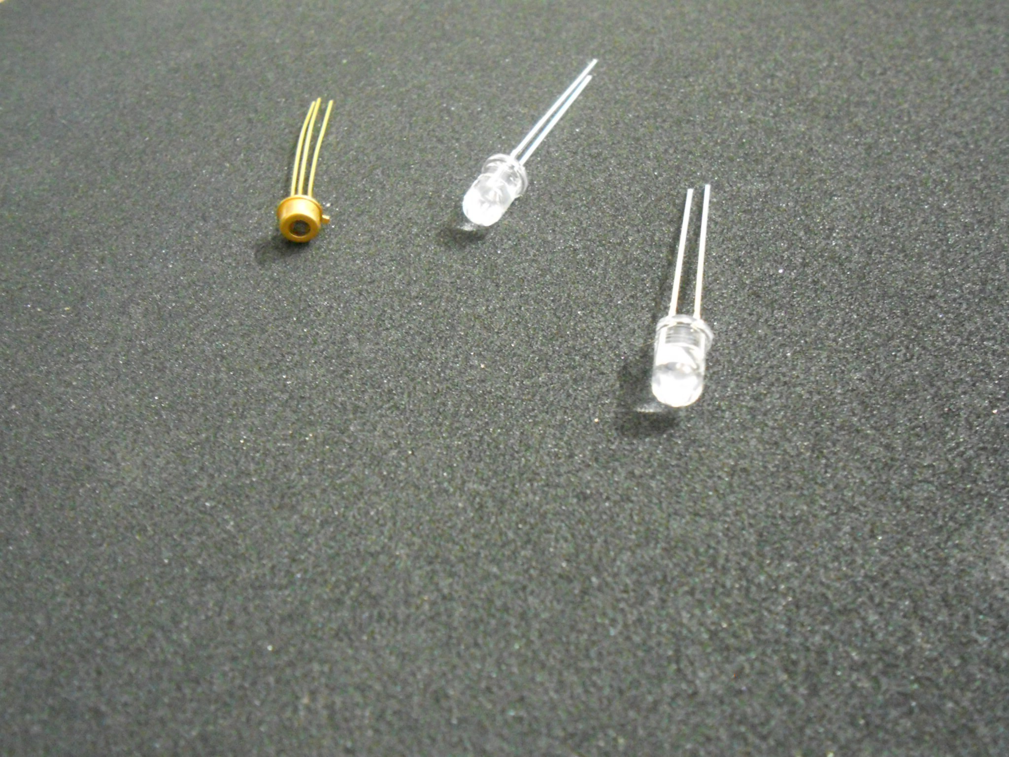
Advances
05/17/2015 at 19:25 • 0 commentsI did some test with the InGaAs photodiode and 940nm LED.
![]()
Due to large area (and capacitance) of InGaAs diode, I had some instabilities in the oscillator. I corrected part of the problem adding capacitors to voltage sources and voltage reference. However, sometimes few seconds are necessary before the circuit starts to oscillate right. The next PCB version will correct this, I think... by adding more capacitance, individual voltage regulators, etc.
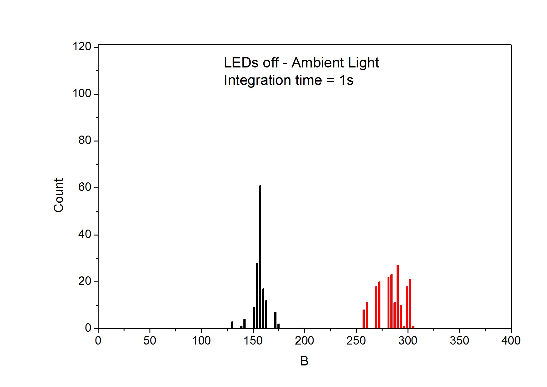
Here I show some measurements with ambient light only (The flourencent lamp have a very very low 800-1700nm emission) varying light position, facing or not facing to the lamp.
![]()
When I turn on the 940nm LED, with 50mA (~50mW) the ADC output goes to ~123000. With earlobe between LED and photodiode the output goes to ~16000. So, a earlobe absorbs 92% of light with 940nm.
The conclusions:
- The ambient/background plus dark current is very low in comparison to the work conditions.
- The circuit is very sensitive and could be better using different settings (smaller 3.3-vref, bigger integration time).
- The ADC max value is enourmous (max output = 4 bi) and, with integration time of 1 sec, I used only a small part (150k) of its maximum, so, I can use integration time of days!! I think it will be enough to get the necessary precision.
- The earlobe absorbs 92% of 940 nm light.
-
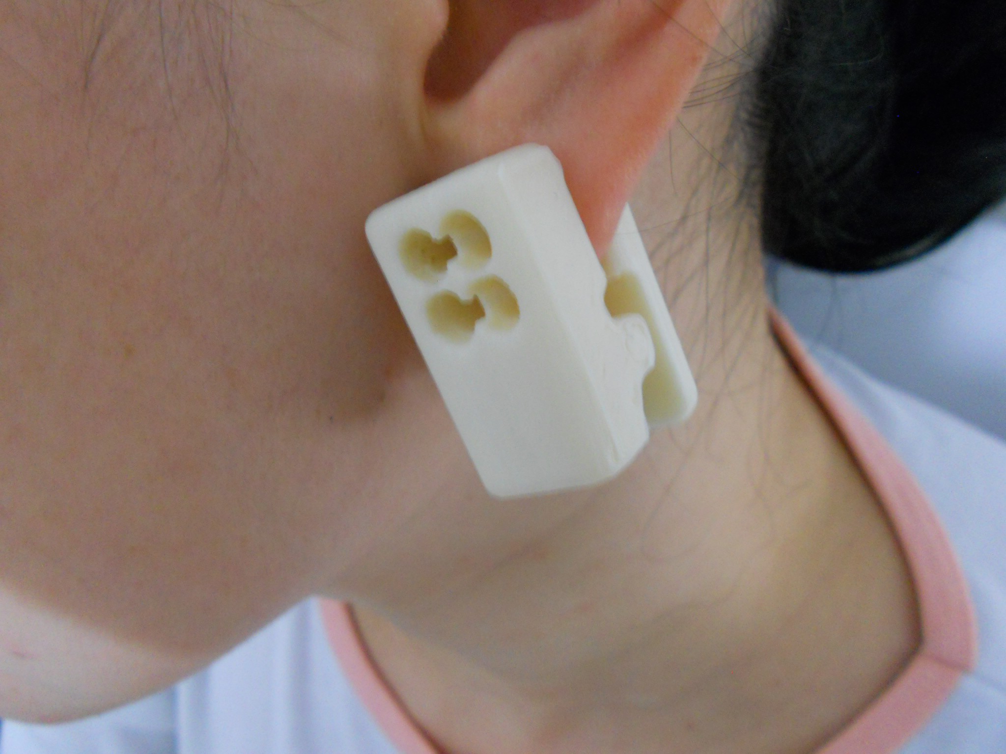
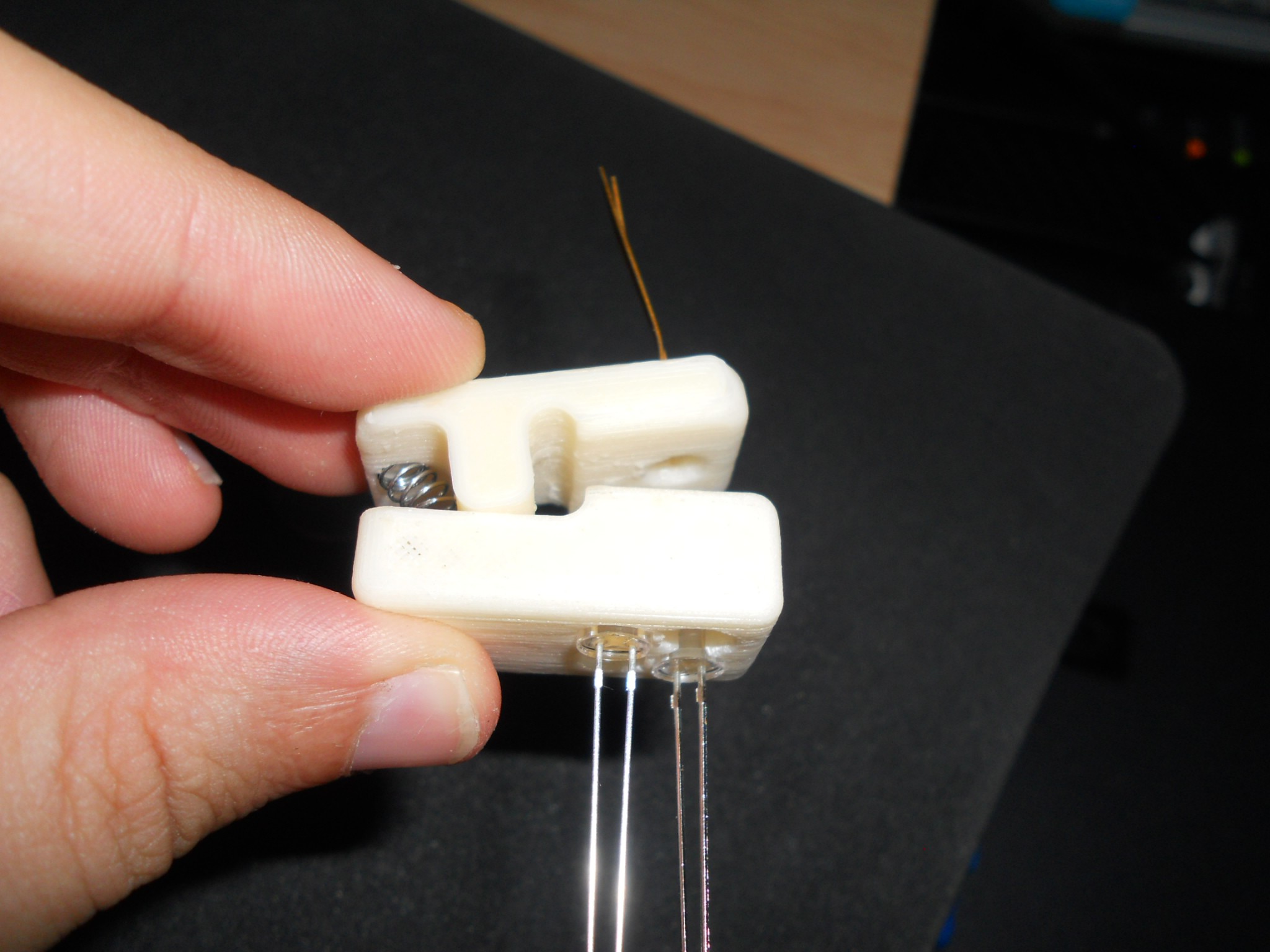
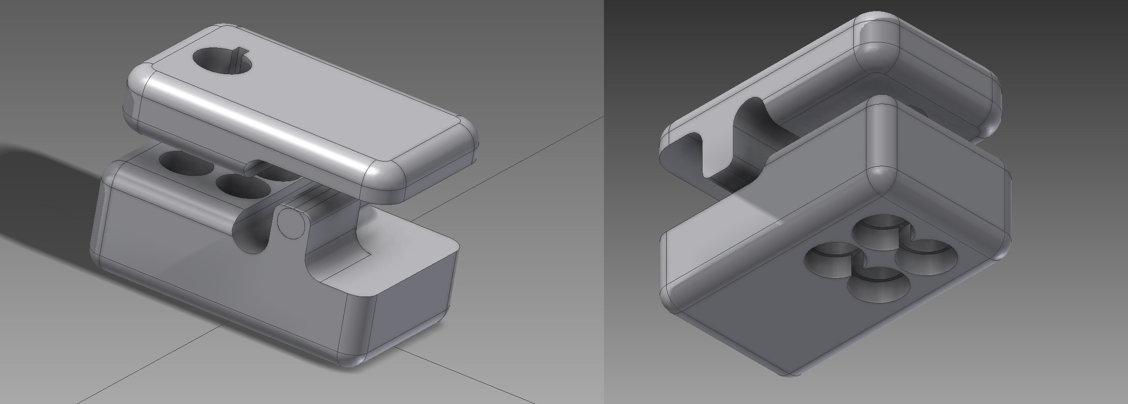
3D printed parts (2)
04/27/2015 at 02:07 • 0 commentsI finally printed the LEDs and diode support, and it worked fine.
I will solder this and try to extract some data in the next days if I can (some busy days are comming).
![]()
![]()
![]()
-
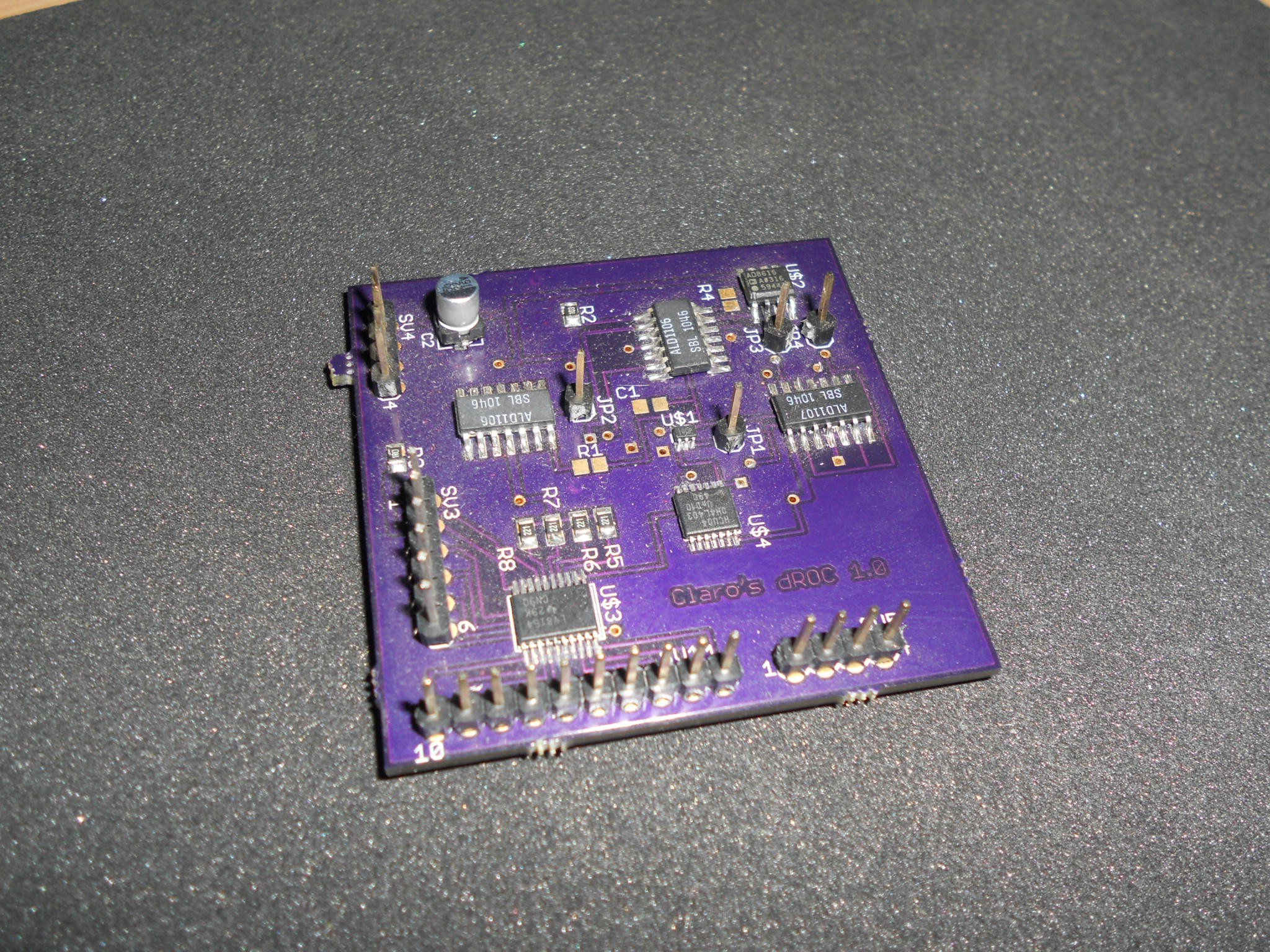
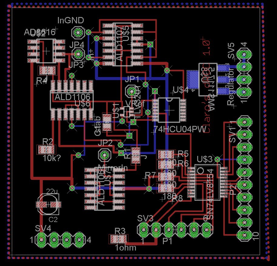
Custom ADC ready!
04/16/2015 at 02:51 • 0 commentsThe PCB from OSHPark arrived some days ago and I finished the solder. I used a conventional solder iron, so it takes some time! :)
![]()
![]()
I did some tests and the electronics works fine! I will post more details in the next few days.
But, bad luck! The x-axis stepper motor drive from the 3D printer (I'm using a printrboard) bugged few minutes before the first print, so, I need to wait a replacement from ebay. A RAMPS 1.4 board with extra Pololu.
Since the reproductibility of measurement is very important, I will wait for a proper diode and led support for the real tests
-
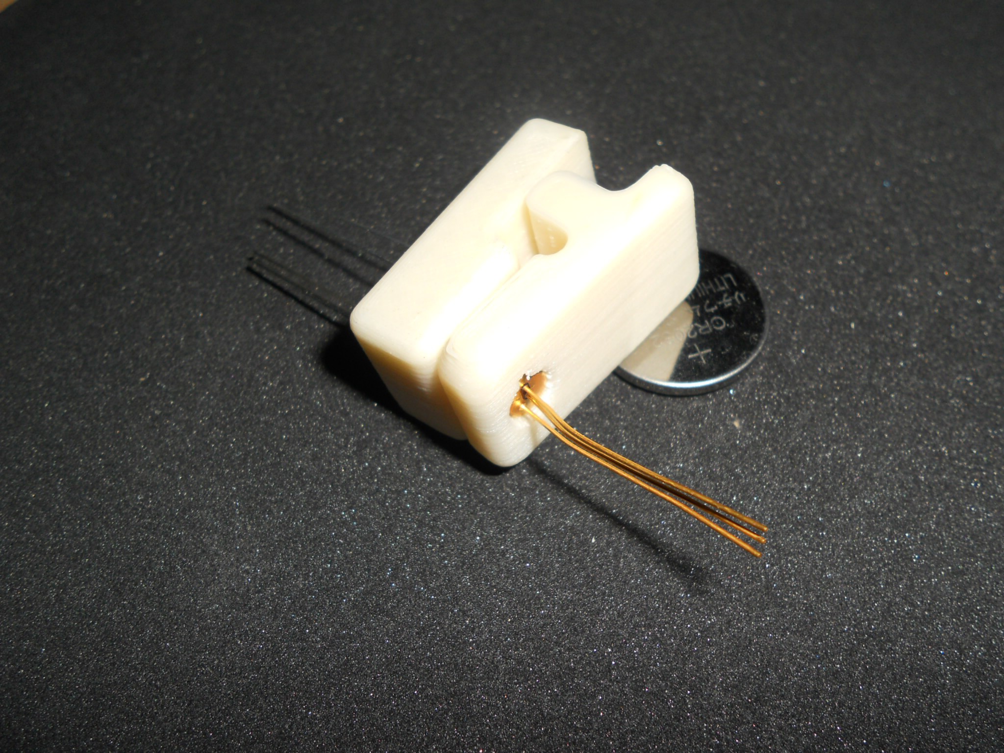
3D printed parts
04/04/2015 at 07:45 • 0 comments1st design of LEDs and diode support, a clip for earlobe or thumb:
![]()
The space was overstimed, so I'm able to put only 4 LEDs. Problaby I will choose 2 of 1550nm, 1 of 940nm and 1 of 850nm.
![]()
I'm just waiting the power source of my new Prusa to print this.
Chocometer
Chocometer is an open source near infrared sensor aiming glucose measurements without pain.