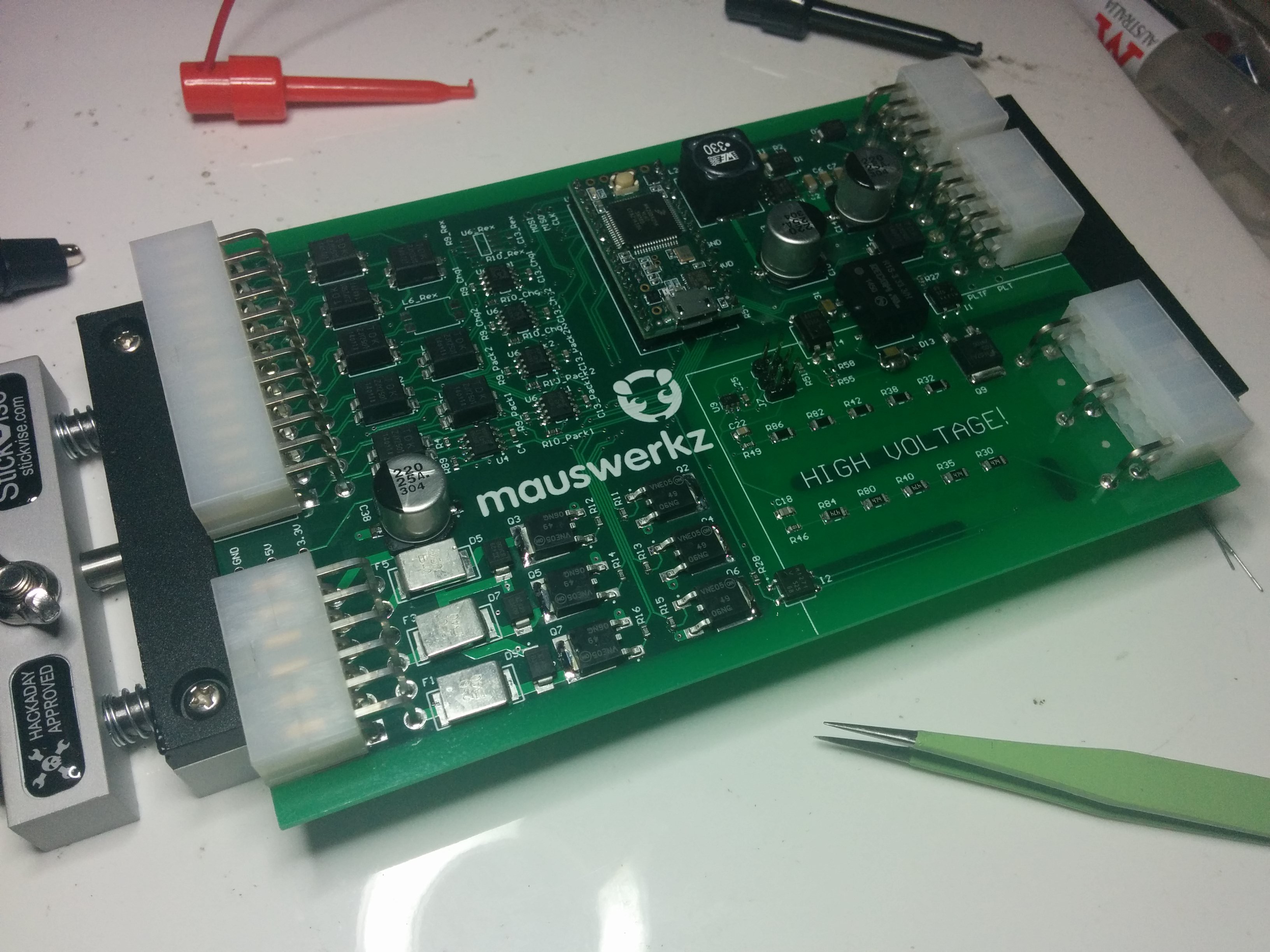
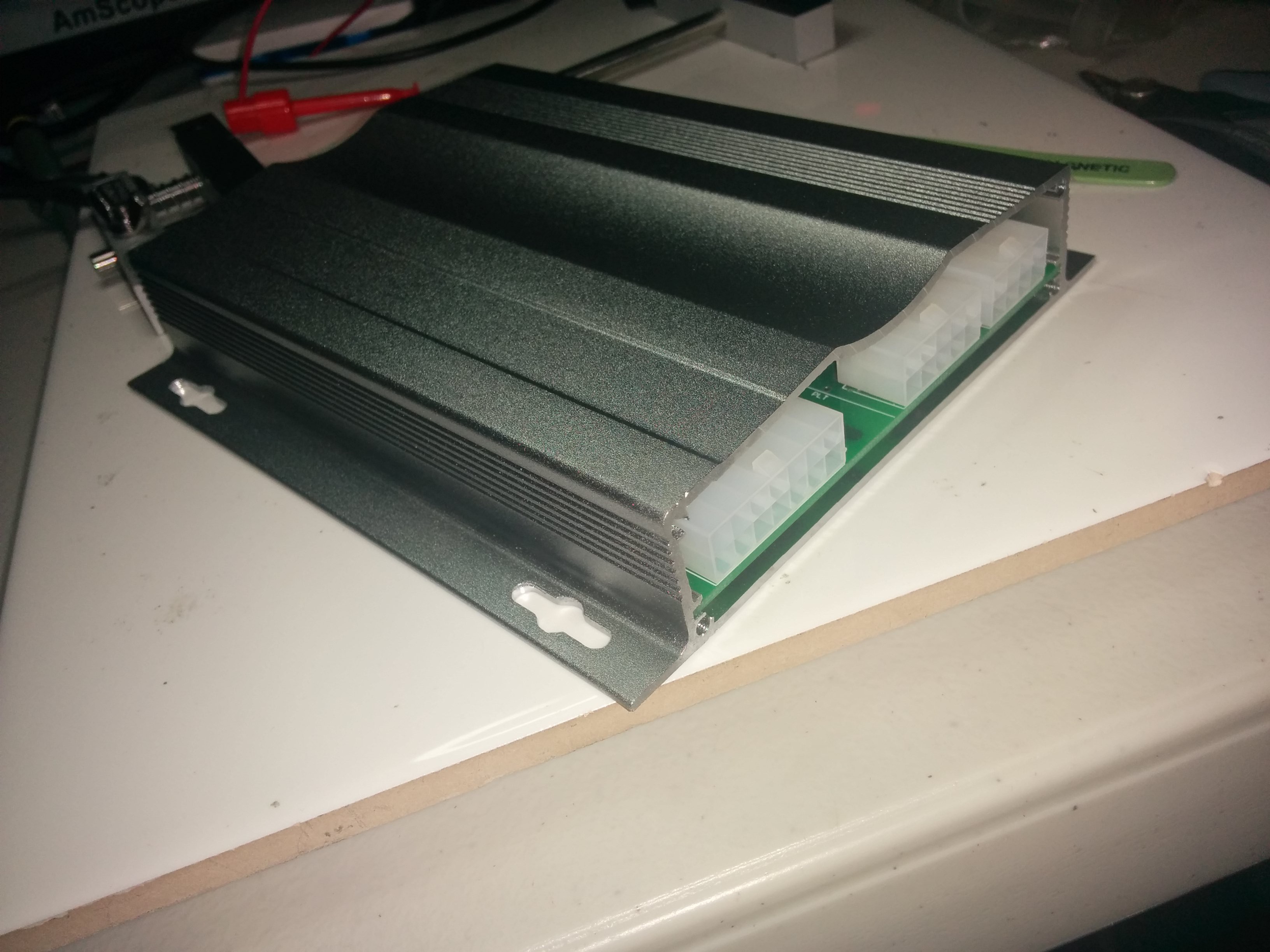
The BMS ECU is populated and coding has begun! So far, so good. It even fits in the enclosure I bought for it! If only I still had my CNC Mill (I left it in Australia), I could cut out the holes in the end covers for the connectors to pass through.
Coding this is going to be "fun". I've built most of the framework for it already. I'm using a series of "metro" timers and a state machine. The state machine will call the correct functions at set intervals depending on the state it's in (charging, driving, standby, etc). I've set up the CAN messages to be staggered to help even out CPU load. For example, I have two CAN busses that I need to send a message to at 200ms intervals. I've set the timer to call these functions every 100ms, but it alternates between each of the two busses with each call. Sending the messages is easy, it's the responses that take time. Have to receive and parse up to 96 cells voltages per bus, plus the temperatures. Should be no sweat on these time scales for the Teensy that's doing the work, but I still like to have things staggered.
Here are a few photos:


 mauswerkz
Discussions
Become a Hackaday.io Member
Create an account to leave a comment. Already have an account? Log In.