Summary
1) The ultrasonic transducer power supply boards found on eBay are, um... unsuited for hacker use.
2) Despite being careful, I managed to burn one out.
3) Apparently, no one else has been able to get these to work, either.
4) I'm a total coward when it comes to high-voltage measurements.
Hackaday Fail
For the project, I had originally planned to build and describe two types of ultrasonic experiment kits: a "simple" unit based on an eBay power supply board with a timed relay, which would be simple to purchase and assemble, and a "designed" supply with adjustable power and microprocessor control.
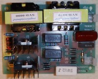
I've since played around with the ultrasonic power supply board that came with my transducer, and have concluded that these are pretty-well useless for hacker purposes. Additionally, I managed to burn one out despite being careful.
My explanation of why these boards burn out so easily is below, after some background info about tuned circuits.
(NB: Apologies for the large images - the http://hackaday.io system doesn't save the image size properly. It looks good while editing, but after posting the images go back to "full size.")
Powering a resonant circuit
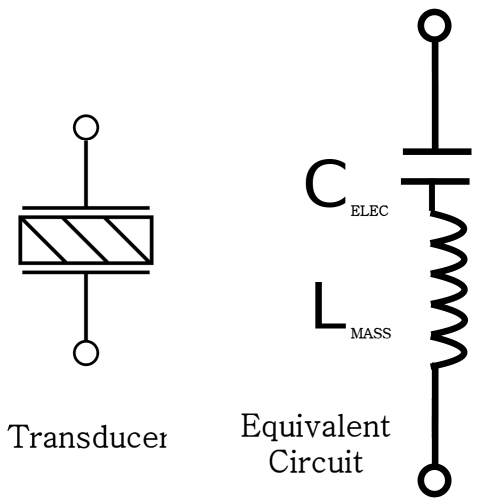
As mentioned in a previous post, an ultrasonic transducer is effectively a series resonant LC circuit: the piezo plate electrodes form a capacitor, and the resonating mass acts as an inductance.
 | 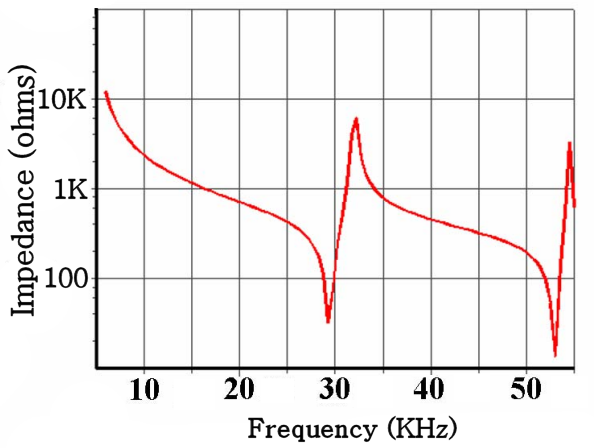 |
Since the transducer is an LC circuit, it presents different impedances to the driving circuit at different frequencies. At its resonant frequency (28 KHz), it will appear to be a 25 ohm load, and when driven off-resonance, it will look like 1000. And driving the device at an intermediate frequency will result in an impedance omewhere between the extremes.
(The high peaks in the plot are the parallel resonant modes, which should be avoided. Most of the off-resonance areas are about 1000 ohms.)
The eBay transducers are rated at 100 watts, so the next question is: "What level of drive voltage is needed to push 100 watts through the device?"
Power is voltage squared divided by the resistance, which in this case is the impedance to the AC driving voltage, so the needed voltage depends on the driving frequency:
Tuned horns and cleaning baths
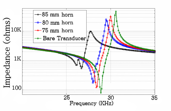
Most ultrasonic applications use a metal horn attached to the transducer to focus the energy into a small area, depending on the application. The horn vibrates at its own resonant frequency, so the resonant frequency of the complete system (transducer+horn) is a melding of the two. Typically, one makes the horn extra long and "trims" it to match the transducer resonance.
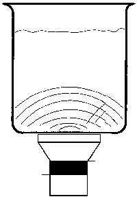
An ultrasonic cleaner connects the transducer directly to a metal bath chamber where the ultrasonic energy gets bounced around a lot.
1) The chamber is square(ish), with rounded corners
2) You don't know ahead of time how much liquid is in the chamber
3) You don't know the density of the liquid (it might not be pure water)
4) You don't know what or how many things are in the water to be cleaned.
Because of this, the cleaner bath will never be in sharp resonance as one would get with a tuned horn. The ultrasonic cleaning system should present a high impedance to the driving circuit in all cases.
The eBay ultrasonic transducer driver explained
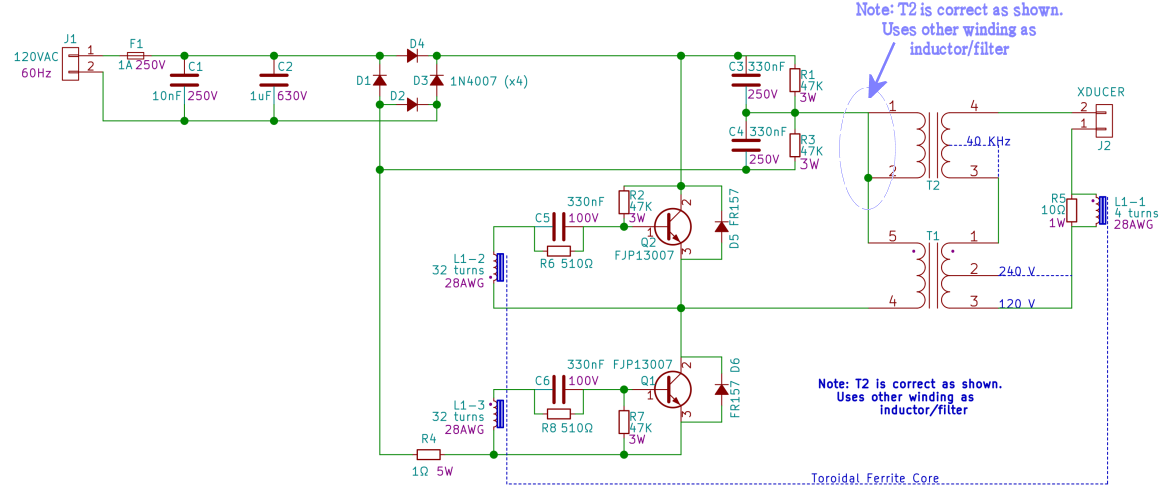
Here's the full schematic of the eBay driver board.
The 120 volt input is rectified (poorly) into 160 volts, then split into a balanced +/- 80 volts by C3/C4. One end of the T1 primary is held to the common midpoint, while Q1 and Q2 alternately switch the other end high (+80 volts) and low (-80 volts). The secondary of T1 amplifies this voltage, while T2 acts as a rude filter for the output waveform. Note that T2 is only used as an inductor - the primary is shorted and grounded to keep it from generating any voltage.
The transducer oscillations are picked up by L1-1 and delivered to Q1 and Q2 via L1-3 and L1-2. As Q1 powers up the transducer, feedback from L1 will eventually turn it off and Q2 on to power the transducer in the other direction. As Q2 powers up the transducer, feedback from L1 eventually turns *it* off and Q1 turns on again.
The output voltage at T1 is about 4x the input voltage from the rectifier/splitter (as gingerly measured using a variac). At full AC voltage, 80 volts becomes 320 volts at the output, which is about right for an off-resonance system.
I believe this is a variation of a Royer oscillator. The system will find and keep the resonant frequency of the "transducer plus system", whatever that may be.
Problems with the eBay circuit
1) It burns out easily
The biggest issue with the eBay circuit is that it has a tendency to burn out.
Referring to the calculations above, the circuit generates voltage appropriate for a fairly high impedance. A bare transducer (nothing attached) will present as a highly tuned circuit with low impedance, drawing some 6x more current than the transistors expect. The transistors burn out within a few seconds (like, three seconds).
(As an aside, this is why ultrasonic cleaner manuals warn about running with little or no fluid. For instance, the Branson ultrasonic cleaner user manual has the ominous: "Do not allow the solution to drop more than 3/8 inch below the operating level line with heat or ultrasonics on. Failure to comply may cause transducer and/or heater damage and will void your warranty.")
2) The generated waveform is crappy
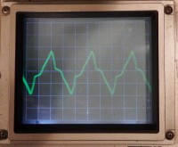
The output waveform is nowhere near a sine wave.
Looking at the circuit, note that the AC is rectified, but not smoothed. With no filter capacitors on the supply, the system is switching bouncy AC at 29 KHz through a high-frequency SMPS transformer.
This might be OK for ultrasonic cleaning as it only makes the rubble bounce around more, but it's not good for the home lab.
3) There's no good way to adjust the power
You could probably run the board from a variac while simultaneously measuring the current, but that's a lot of effort. Additionally, if the system goes out of tune for whatever reason (such as the transducer heating up) the power will drop, and if you adjust the power and the system comes *back* into tune you risk burning out your board.
It's a lot of trouble to go to, and you have to keep watching it.
Also, the variac doesn't have much resolution at 1/6 full scale, and it's not clear that the feedback circuit would even work at that low voltage.
4) The circuit is nigh impossible to measure
A scope probe pretty-much anywhere will change the circuit behavior in bad ways.
Parting thoughts
As near as I can tell, no one has posted a YouTube video demonstrating a home-built ultrasonic cleaner. (There are some posts that use motors and orbital sanders, but none that are both home-built and actually ultrasonic.)
Additionally, this link suggests that *no one* has successfully home-built an ultrasonic cleaner. This instructable is the only real home-built ultrasonic cleaner I could find, and he's using a $200 professional board (not the eBay board) *and* he burned one out in the process.
I realize that used cleaners start at around $50 on eBay, but still - affordable 100 watt ultrasonic transducers would seem to have good hacker potential. I'm surprised no one else is using them for projects.
I'm currently designing a power supply based on the 3525 PWM controller. These have a sync input which can be used to slave the device to an external clock. I think the transducer feedback can be used as this input, which would make the system self-resonant.
 Peter Walsh
Discussions
Become a Hackaday.io Member
Create an account to leave a comment. Already have an account? Log In.
Hi, im Federico and manufacture ultrasonics generators for cleaning from 6 years ago (200W-3000W), in the cleaning and the weldering are diferent techniques because in the cleaning systems have a lot of transducers in parellel and its very dificult follow the Fo, for that reason the best solution its a sweep in the frequency to exite each transducer correctly, and with this prevent the dead zones and the exesive resonance in only some transducers, can make a closed loop but with uC to generate a compensation, but a lot of time its Hard Switching, need use good IGBTs. In the weldering systems its diferent 1 Generator its only for 1 Transducers, and with a cloosed loop can follow better the Fo, Soft Switching almost time, dont need sweep of frequency because only have one. Thats its my experience.
Are you sure? yes | no
Hi peter.
I have two langevin type transducers. I am trying to create an ultrasonic levitator using this. I have tried with few driver circuits. I was successful in low power levitation. But while trying it for higher powers, none of the circuits are working. Can you suggest a driver circuit ?
Are you sure? yes | no
Peter,
I believe the original closed loop approach used on the cheap CN controller, where the output generates the frequency is very elegant but has a problem in that it is always hovering around the resonance frequency and unable to work off-resonance frequency.
Sometimes you want to slightly vary the frequency fed to a mechanically modified transducer to obtain maximum effect, in my case microcavitation.
To this end I created a version of the cheap controller where I replaced the primary winding on L1 with my own, powered by a half bridge driver that gets its input from a $0.90 PIC microcontroller. I exchanged the J13007 transistors with a couple of FETs and replaced the base resistor/capacitor combination with a resistor/diode.
The net result is that I now have a relatively simple driver circuit (compared to the solution I had earlier with the 3525, a controller and a dual digital potmeter) that powers a 60W ultrasonic transducer in a wide frequency range. The circuit is quite resistant to burning out due to transducer mismatch. And it runs very cool too.
The circuit is open loop; I dial in the output frequency using a potmeter on one of the PIC's ADC inputs. I am working on a version where the input current is measured and used in automatically selecting the right frequency.
Paul
Are you sure? yes | no
I started typing a response, and it turned into a project blog entry :-) Check it out.
You're probably right about the choke, I should have removed it from the board and tested it. Looking at the generated waveform, the system was obviously very poor quality, and I was able to get a couple of industrial ultrasonic generators from eBay for about $50, so I haven't followed up on that board.
My ultrasonic controller is mostly an open-loop control of frequency, which I now believe is the wrong approach. I've been researching closed-loop control for frequency, and I think I have an idea for a much better circuit. More stability, relieving the micro of responsibility for frequency control.
My new circuit isn't specifically for ultrasonics, but could be adapted for it. It's on my list to build out a POC circuit for ultrasonics as part of the development of my new board.
You might like the portable resonance detector I'm working on. It's what one would use to detect and tune transducers and horns.
Are you sure? yes | no
Hello Peter,
Thank you in advance for any help.
I accidentally bought a 110V 60Hz driver, in my region we have 230V 50Hz. If I use a variac to step down the 230V down to 110V would the 10Hz difference in supply frequency have any detrimental effect on the efficacy of the driver? I intend to use it as an ultrasonic cleaner.
Are you sure? yes | no
Hi Peter,
Are you still working on this project? It interests me because I more or less traveled the same road as you did, going from the standard Chinese driver to a home-build one using a 3525 controlled with a micro controller and a dual digital potmeter. All this while being much more of a digital person instead of the analog one needed for a project like that. Nice to see someone else has been there :-)
As an aside, I believe that the choke (T2) in the original design does not have its primary grounded. It does not have a primary; only 2 of the 14 (or 16) pins are connected to copper wire. If there was a primary and you would short that, the entire circuit stops oscillating. As accidentally demonstrated by myself with an extra winding on L2 to power an LED and shorting that....
Paul
Are you sure? yes | no