Peter Walsh
-
I have done it! Qapla'
08/31/2015 at 01:46 • 1 commentFinally, a solution!
I have driven electrons into resonance, and I can hear the lamentations of their women! Bwahahaha!
.) I have a solution to the problem that has been vexing me for weeks.
.) I'm confident I can make working boards (PCB layout, etc.)
.) The new driver is simpler and less expensive
.) The new driver can power transducers from 20 kHz through 40 kHz.
.) The new board will include measure and tune functionality, previously on a separate board
Statement of the problem
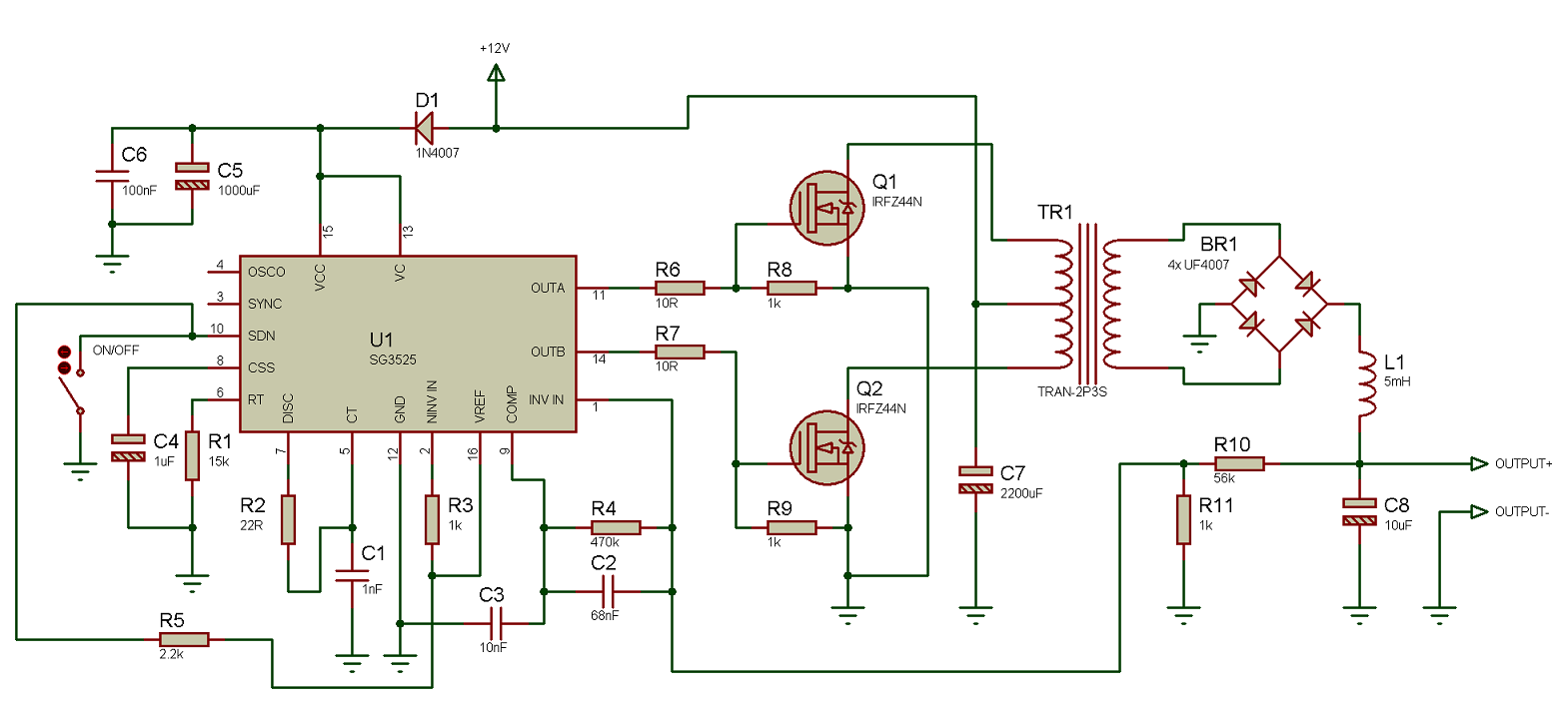
The UC3525 PWM controller uses an RC for timing. This is an analog frequency generator, and is subject to (frequency) drift from factors such as noise and temperature variations.
![]()
To compensate, the R of the RC circuit uses a digital pot controlled by a microprocessor. In theory, the micro adjusts the pot as needed to make the output frequency match the requested frequency.
This worked on paper and in prototype. The micro reliably kept the output within 1 Hz of the requested frequency with no transducer attached.
For outputs greater than 50 watts however, the noise affected the control and measurement systems, causing the frequency to drift faster than the control algorithm could keep up.
As the frequency swept around, the transducer would go into and out of resonance, which varied the power faster than the power tracking system could compensate.
So to summarize, the system couldn't maintain a stable frequency or power output.
Digital frequency FTW
The new circuit uses an AD9850 to generate extremely accurate frequencies with 32-bit resolution. This solves all of the horn tuning problems caused Arduino generated frequencies: The Arduino only makes square waves and at poor resolution, the AD9850 solves both of these problems.![]() In a previous build log I noted that the SG3525 has a SYNC input that can slave chips to an external frequency. (And apparently no one has ever used this feature.)
In a previous build log I noted that the SG3525 has a SYNC input that can slave chips to an external frequency. (And apparently no one has ever used this feature.)On a whim I routed the extremely accurate AD9850 output to the SYNC input and... it works! It's completely stable to over 150 watts.
The SYNC input is thus digital, with noise immunity per the static discipline.
![]()
It's also "set and forget", so the micro no longer needs a frequency-following system, or even a frequency *measuring* system. This greatly simplifies the software.
And as a bonus, the AD9850 goes from DC to 2MHz, which means the system should run other transducers such as the 20 kHz and 40 kHz types.
There's some devil in the details, but I feel confident I can design a board that's simple, stable, and easily controlled.
-
Hitting a Brick Wall Tango
08/27/2015 at 19:36 • 0 commentsTL;DR
.) Looking to hire someone to solve a n electronics problem
.) New driver board is partially working
.) Version 2 of some of the project pieces
.) GitHub groups open for contributors
Looking to hire a consultant
I'm having a lot of trouble designing the power-drive section of the new board, and would happily pay $100/hr for someone to just slam dunk it for me.
This *should* be straightforward: it's a common ham radio circuit, and there's lots of people with switched-mode power experience who should be able to get a prototype working in an evening.
I need to boost a 1v p-p sine wave to 12 volts at 10 amps and I'm done - the rest of the board is working, the microcontroller works, the PC software works, the horns are tuned, and the transducers sing.
I only need that 1 piece of the puzzle to complete the project. A complete description is here.
Know someone who can help?
(NB: I am not looking for advice. Please don't contact me just to say what I should do, I'm looking to hire someone to do the work.)
New board design is partially working
The new board design uses an AT9850 sine-wave generator for sub-hz resolution. This works perfectly.
This has solved all of the problems with transducer and horn tuning. I can now cut horns close to a transducer frequency, and see very clearly how well tuned it is and how to trim it for resonance. Horns can be tuned using a mill, a lathe, or a CNC mill (quite possibly a Shapeoko would work), so lots of hackers should be able to build one of these if they want.
I'm trying to integrate the tuning circuit into the power driver board as a separate output, so I don't have a board image or schematic to show. But it works.
The new circuit will have a relay (a real one, not solid state) to disconnect the transducer during the tuning process, so that cutting vibrations won't generate back EMF spikes that kill the tuning circuit.
Power drive doesn't work, need new solution
![]()
I had originally planned to convert the 1v p-p sine wave into PWM using a class-D amplifier (that part works) and switch a pair of half-bridge motor drivers in H-bridge configuration with the transformer primary in place of the motor.
This should have worked.
The BTN chips are made for inductive loads, they can handle the frequencies, they've got plenty of power (40 amps, of which I only need 10), they're made for PWM control, they have logic-level inputs, and they've got embedded current sensors. What's not to like?
The problem is they don't work.
The logic-level inputs don't behave like binary inputs - sometimes a high level will turn the device on, and sometimes it won't. No amount of fiddling or driver chips or adjusting input resistors affected the behavior. And yes, the datasheet specifically states that the inputs are logic level, with reasonable logic-level mins and maxes that *should* be triggered by a 74HC14 driver chip.
Also the outputs seem to be deceptively analog - the output levels sometimes go up to the 12-volt rail, and sometimes they don't. This is particularly evident when using a PWM signal, since some pulses are 12-volt high while others are not. It's not a speed issue: sometimes the relatively slow pulses peak at 10 volts, sometimes they peak at 12.
The manufacturer has a 24/7 help line which wasted a lot of time - I tried chat, phone, and E-mail, and each time the operator advised me to call back using a different channel. I'm still waiting on a response from the "open a ticket" answer.
Several frustrating days later and I'm giving up. These chips aren't ready for mainstream.
Project, Version 2
(Oh, I am *so* jonesing to try making ammonia with this system, but I need to finish the driver circuit to stay in the contest. I'm focused on that all the time. Even in my sleep.)
I've revised some of the project hardware.
![]()
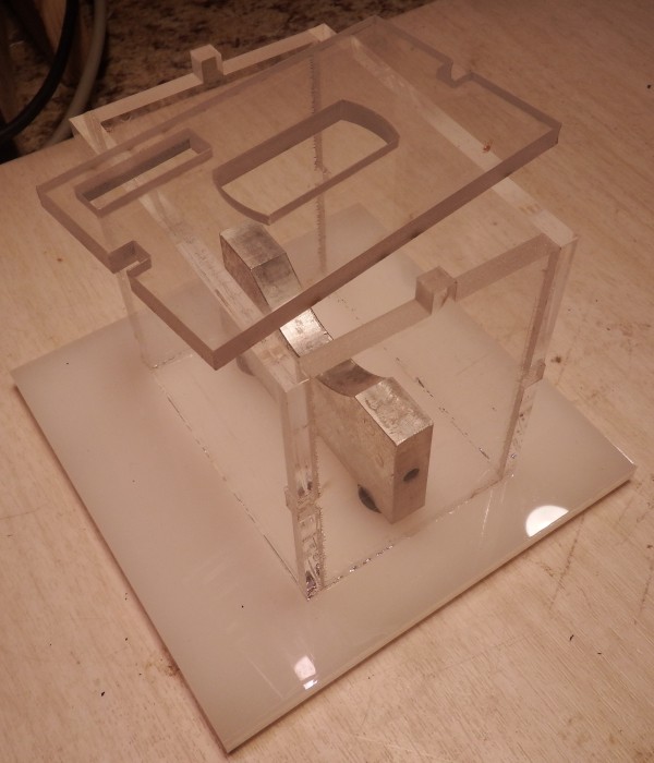
The new reaction chamber has alignment notches. If you look closely you can see glued notches in the edges of the main body, and the unglued notches in the lid keeps it from sliding around during experiments.
It's now much easier to assemble and glue.
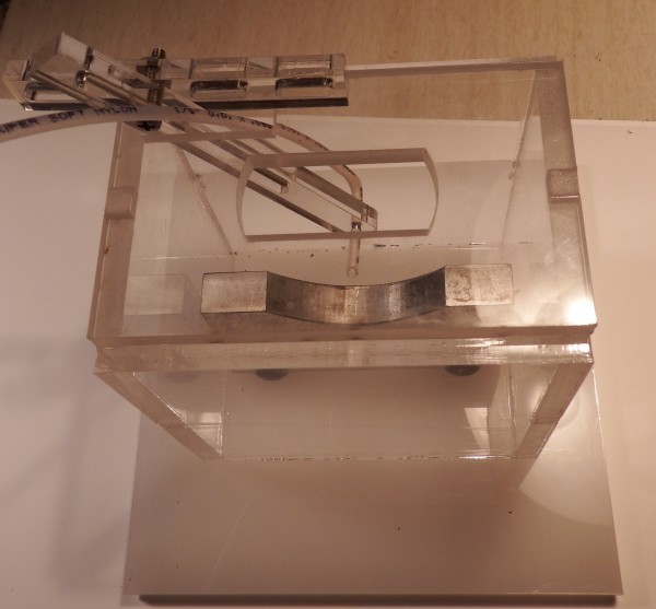
A new tube holder allows me to adjust the position of the end of the tube in 3 dimensions without getting my fingers wet.
This is a little wobbly - could probably use a version 3.
![]()
The transducer flats are bigger than a common box-end wrench, and steel wrenches have a tendency to mar the aluminum horn and steel transducer, so I cut out an aluminum wrench using a CNC. Version 1 and version 2 in the image here.
![]()
Github groups
Schematics and software are up on GitHub.
The hardware will go up soon, I just wasn't able to get to it in time for the contest deadline. Hardware consists of transducer mounting hardware, the reaction chamber, wrenches... mostly DXF files for the laser cutter and some gcode.
I also created two GitHub groups for people who want to help out: "Sonicators" for people who want to help develop the ultrasonic system, and "AmineGroup" for people who want to contribute experiments and projects using the system.
Contact me on .io or through GitHub if you want to be added to either group.
NOTE: You do NOT need to be a group member to access the files. The repositories are open source, they can be downloaded and used by anyone. The groups are for people who want to help. Group members have write-access to the repositories.
-
Secret Sauce Revealed!
08/03/2015 at 23:25 • 4 commentsWhy this might work when other attempts have failed
Several readers pointed out that others have tried to fixate Nitrogen using ultrasonics, and none succeeded.
Supeno's paper "Sonochemical Fixation of Nitrogen" reviews the previous attempts and has a good explanation of the difficulties involved. If you're interested, it's an easy read and provides good background information for this project.
Of course you don't do what others have done and expect different results. For different results, you have to do something no one has tried. Preferably with a rationale for why the differences are important, and how they might lead to success.
So here at last is the secret sauce: what I intend to do that is different from previous attempts!
Difference 1: Focused ultrasonics
Previous attempts used ultrasonics at low power density. More specifically, previous attempts made no attempt to focus the ultrasonic energy to high density.
Supeno experimented with a tuned chamber that, as far as I can tell, generates standing [planar] waves. The energy within the chamber is the transducer power divided by the base area times the Q of the tuned system.
He used roughly(*) 50 watts from a transducer 2.125" in diameter, which is 2.2 watts/cm^2, which is not a high energy density. His paper doesn't list the tuned chamber specs, but if the Q is 20 then the energy density would still be only 44 watts/cm^2.
(*) Various depending on the experiment, but in this range.
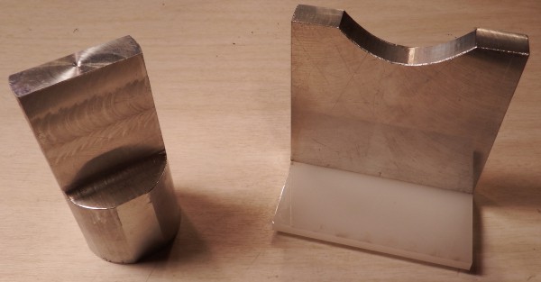
![]()
![]()
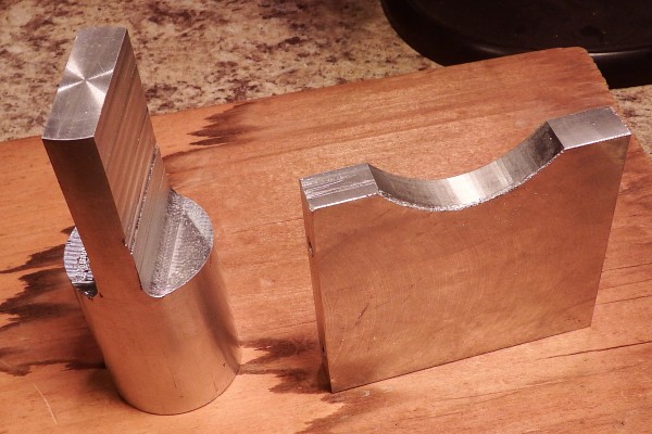
For my experiments, I've milled a rectangular end horn and a parabolic reflector anvil.
In theory, the rectangular horn should generate plane waves which will be concentrated by the parabolic reflector. This should produce enormous energy densities and pressures, which are different experimental conditions from the other attempts.
Difference 2: Directly sonicating the gas
Previous attempts used Nitrogen and Hydrogen dissolved in water. Specifically, in previous attempts Nitrogen and Hydrogen were bubbled through water using an air stone, and sonicated.
![]()
Hydrogen and Nitrogen are largely insoluble in water, so one would expect such a system to have a poor yield.
...but note that previous experiments did produce tiny amounts of ammonia. That's important!
It takes 3 moles of Hydrogen to produce 1 mole of ammonia, so dividing the Hydrogen solubility by 3 tells us that the most ammonia we can get from 100cc of water using this method is about 50 micromoles(*).
Further, the molar proportion of dissolved Nitrogen to Hydrogen is 0.8:1, which is nowhere near the ammonia ratio of 1:3. This reduces the maximum yield: with less Hydrogen available than needed, fewer activated Nitrogens will encounter Hydrogens to form ammonia.
Supeno experimented on 100cc batches and produced around 5 nanomoles of ammonia(**). Perhaps ultrasonic production of ammonia might work with a different setup.
(*) Gloss gloss, such as continually replenished gases and not accounting for sonification time.
(**) Various, depending on experiment, see paper.
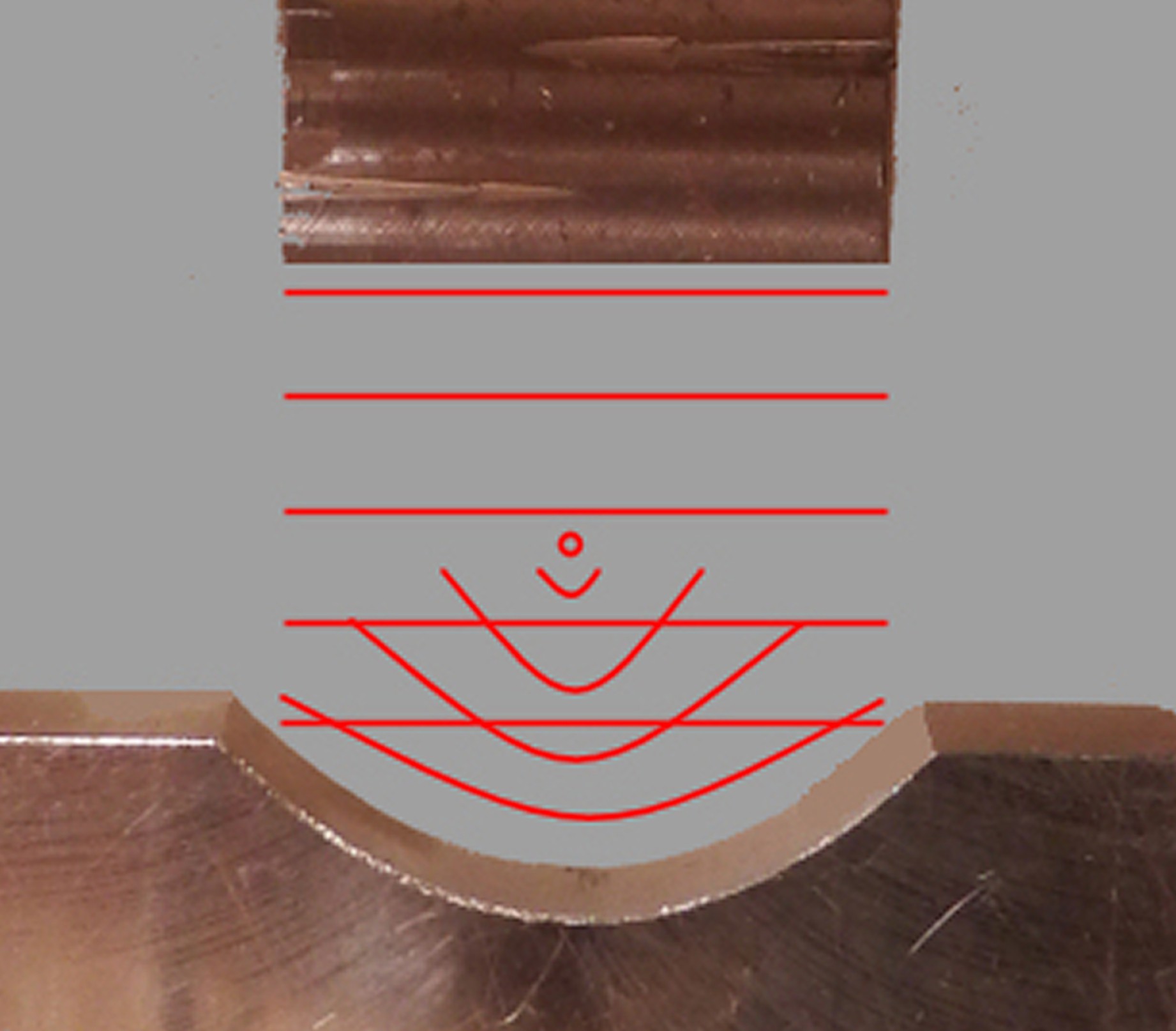
![]()
My system uses a capillary tube to hold a small bubble of gas (mixed to molar proportions) at the focal point of the parabolic reflector.
The hope is that focused ultrasound will compress the bubble to high pressures, generated ammonia will dissolve into the surrounding water, the bubble will shrink, and gas will be replaced as needed by a mass flow controller.
For now I'll manually control the mass flow via serial port, but if ammonia is generated it seems reasonable to automate this using a webcam and OpenCV.
Modification of parameters
Experimentation is a form of search, and to increase the chances of finding something you need a wide search area.
With this setup I can vary the ultrasonic power delivered to the bubble, the size of the bubble (a little), the temperature of the water, and the gas mixture (proportions, or adding a buffer gas such as Argon). I can also dissolve things in the water which might catalyze the reaction, and I can try to make other compounds such as oxides of Nitrogen.
My plan is to take measurements under various conditions, look for trends in ammonia formation (if any), and zero in on the most effective experimental regime. At that point I can estimate the efficiency and compare to the Haber process.
Video of the system in action
Here's a video of the reaction chamber showing horn and anvil. It doesn't have a capillary tubing mount (under construction), but I have an air bell for collecting gas, Hydrogen and Nitrogen generators, and a mass flow controller.
This the same effect as the 2KW cavitation mentioned in the a previously mentioned video, at a smaller scale.
The cloudy wisps extending from the bottom of the horn are flows of cavitation bubbles. I think. Power output around 50 watts, through a cylindrical horn sculpted to a 44x12 mm rectangular(ish) end.
![]()
![]()
-
Project Roadmap
08/01/2015 at 02:26 • 0 commentsWe're coming to the run-up for the Hackaday Prize judging, and Mike Szczys mentioned offhand (at Artisan's Asylum, last week) that they're planning a blowout final interim prize before the Aug 17th deadline.
This seems like a good time to do a project roadmap and retrospective. I wanted to get my regrets out of the way before the contest begins in earnest :-)
Project Future Roadmap
I'll be exploring the Haber process using various means (mostly ultrasonic) for the next couple of years. I was planning this before the contest announcement, and I'm in it for the long haul. What this means is that The Hackaday Prize isn't my primary motivation. One way or another I'll be doing this long after the contest has ended; though, probably not with weekly updates in "diary" style.
So the roadmap for the project during the contest period, and after is:
- Take the project as far as possible in the Hackaday Prize contest. The prize awards are mid November, so that's an outer limit on this phase. (Estimate: End of August to mid November, depending on how far the project gets.)
- Take some time off to decompress and cleanse my mental palate. (Estimate: 1 month.)
- Do some project house cleaning: adding README's, verifying file headers, rearranging directories... general prep work for first release. (Estimate: two weeks.)
- The ultrasonic system will go up on GitHub as a public repository. Anyone can download the schematics, source code, hardware layouts and everything else.
- The chemistry/experimental side will go somewhere else, possibly Hackaday.io.
- The GitHub account will be open to anyone who wants to join the project and otherwise help with development.
- The chemistry part will be open to anyone who wants to discuss and make suggestions on what experiments to try. It'll also be open to collaborators (ie - join the Hackaday.io side as a contributer).
Things that should be different
I've made a lot of progress in figuring out how to do things for the project, but there are some rough edges. Individual rough edges are not a problem, but they combine to make the final project a bit difficult. I've been forging ahead due to contest requirements, but I really need to revisit some design decisions and rework some of the earlier phases.
Horn Tuning Circuit
Don't use the Arduino to generate frequency
![]()
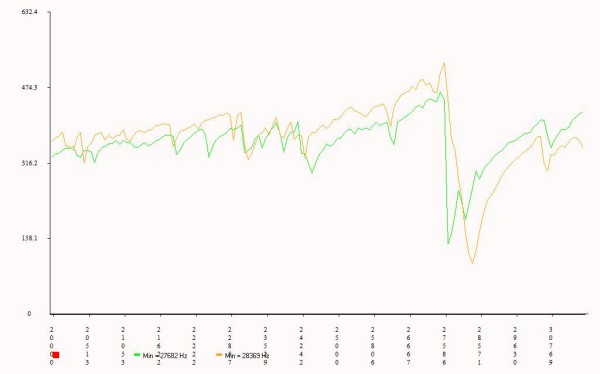
As mentioned in a previous build log, an Arduino has about 100Hz of frequency resolution at 28KHz.
This seemed reasonable at the time, but in practice I'm finding it difficult to tune the horns using that resolution. The transducer has a very thin resonance window, 25Hz or so, and you can't judge how close the horn comes to that frequency.
The image on the right shows the bare transducer response (orange) and horn response (green) during the tuning process. The 28KHz peaks "mostly" overlap, but it would be nice to see a more fine-grained resolution here.
Using a faster processor could work, but isn't the best solution.
Don't use square waves
Square waves are easy to generate, and it *seemed* like a good idea because you can turn them into sine waves by filtering. In reality, this bring a host of problems to the circuitry, and filtering never completely works. Especially at 400V and 100 watts.
New design
I've been working out a better design using AD9850 to generate pure sin waves with sub Hz resolution. It's a little more expensive, but a demo board including resonator is about $8 on eBay, which is cheaper than the bare chip from DigiKey. It's "set and forget" from the uController, reduces the board chip count, and greatly simplifies the software. The pure sin waves should be easier to filter than square waves.
I think the generated sine can be split into positive-going and negative-going parts, then fed into a class-D amplifier to run the power driver board. The class-D PWM should generate a pure sin wave out of the transformer, while keeping the FETs either completely on or completely off.
I'll be working on the new design during the contest period.
Horn Tuning
It's difficult to turn down horns on a lathe due to their length. A standard rest (follow or steady) will badly gouge the surface, so you need a "wheeled" rest, which is typically too small for a horn.
A metal cutting table saw (or radial arm saw) blade will reliably cut a horn blank, and a small CNC (one that can cut aluminum) can carve down the profile. Then the CNC can progressively face the ends while measuring the resonant frequency. This is *much* easier than chucking and unchucking the horn during the tuning process.
CNC horn cutting and tuning works well, and small CNC's are probably more hobbyist accessible anyway.
Don't connect the transducer to anything while adjusting
![]()
CNC'ing the horn with the transducer attached generates massive voltage spikes into the measurement circuitry. Simply *attaching* the horn to the transducer while connected is enough to fry the measurement components. Sxperimentally determined, hindsight is 20-20.
Isolate the transducer except while measuring
The new power supply can make the AD9850 pure sin wave available, so you won't need a separate board for tuning.
Also, a relay can keep the transducer disconnected except during measurements. Otherwise the relay will short a low-value resistor across the transducer to prevent voltage spikes.
Better mounting while tuning
The transducer mount for the tuning process could be better. The system needs to hold the transducer and horn steady enough for the CNC to face the end, but lightly enough so that the tuning process still works.
Right now I'm loosening the bracket before each measurements. If I could eliminate this step, I could completely automate the tuning process.
Step horns don't work at all
![]()
As part of the project I'm reproducing Lindsay Robert Wilson's step horn - and not having any luck. My parabolic horn tuned up exactly as expected, but the step horns... nothing. The system behaves as if the step horns aren't connected at all, and I haven't the first clue why this is.
I've got 3 step horns of various configurations, one shown here, and none of them seem to do anything.
I'm completely at a loss as to why this is.
Anyone have experience with ultrasonic horns and can give me a hint?
-
Update, July 20
07/21/2015 at 01:29 • 0 comments1) Made final board schematic
2) Software is coming along
3) Lots of features added to board/software
4) Semi automated horn tuning seems to work
5) Horn blanks can be cut with a table saw
6) Power control works, but not very well. Probably due to noise.
Added lots of features...
The Arduino controller had leftover g'zintas and g'zoutas so I added to the project:
1) Two inputs.
2) Two outputs.
3) Two LEDs.
4) A buzzer.
5) Power rails from the ATX controller brought out to screw connectors
Inputs and outputs are opto-isolated, so external equipment can be isolated from the controller. The I/O can be linked to software events in various ways. For example, a switch connected to an input can give direct control of the transducer output, an output can trigger a system when the transducer is on, and so forth.
Everything can be controlled by the serial interface, so the user can write their own logic to measure and control things. There's even a left-over I/O for future use.
Power rails from the ATX are convenient for powering user equipment: 3.3V, 5V, and 12V (and GND) are brought out to screw terminals.
(I 'kind of went overboard adding extra hardware and the software to drive it. The system can now be described as "feature rich" :-) On the plus side, I can't think of any more features the system needs.)
The software is controlled via 2(ish)-character commands over the serial port. Any serial port program (putty, hyperterm) can be used, direct user control isn't hard, and I have a perl interface library for program control.
Board schematic version 1.0
The driver is still having some problems, but it's close enough that I'm going to make boards and debug from there. The hand-wired board is getting a little tough to deal with.
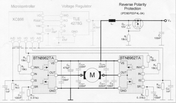
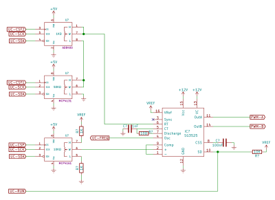
The final schematic is in 4 sheets, here's one:
![]()
The power control isn't working very well, and I think this is due to noise in the circuit from the generated output: there's 2 volts of noise on the ground rail, and I think it plays hob with the RC timing of the PWM chip.
I'm not sure what to do about this. I plan to proceed with board layout, and separate the driver and controller ground planes by a single trace that can be cut. Maybe a 100 ohm resistor between the two grounds will dampen the noise. (There are decoupling caps on all ICs.)
Noise on the 12-volt rail also affects the current measurement, and putting this through an RC integrator doesn't seem to help. Maybe a stepped filter between the current measuring chip and the transformer would fix this.
I don't have an EE background, so it'll probably take awhile to sort this out.
Any suggestions?
Cutting aluminum on a radial-arm saw
I tried a metal-cutting blade for slicing aluminum to make a new horn.
This seems to work well enough - the cut end has a shiny "pebbled" finish which looks nice artistically, but not the flat mirrored finish you get with machining. It's also very slightly angled relative to the body of the rod, so it still needs to be faced off.
Still, this is much *much* faster and more accurate than bandsaw cutting. I can cut about a horn a minute with this method, and they only need a quick 10 thou facing cut on the mill. Also, I can cut the horn to within 10mm of the desired length without having to worry about bandsaw creep.
I also got a metal blade for my table say. I'm *considering* making a jig that positions a horn blank over the saw blade and allows the user to slowly rotate the blank. Possibly using bearings.
If that works, then it should be possible to make horns on a table saw without a lathe, which would put the project in range of many more hobbyists.
![]()
![]()
Semi-automated tuning
A small CNC mill can automate much of the tuning process.
Normally, to tune the horn to length you chuck it, face off one end on the lathe, unchuck it, mount it on the transducer, and measure the frequency. This is tedious and time consuming.
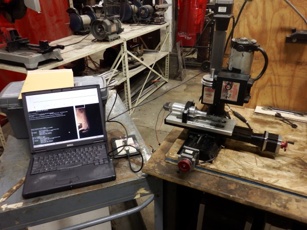
I made a mount for the little sherline mill at the space and wrote a program to go back and forth over the end with an end mill.
Now I can keep the transducer and horn as one assembly, measure the frequency, and run the program to slice off a small piece. Much, *much* easier.
One thing of note: Unhook the transducer from the computer while milling. The generated back-emf from the transducer (due to vibration) can kill your serial port. TIL
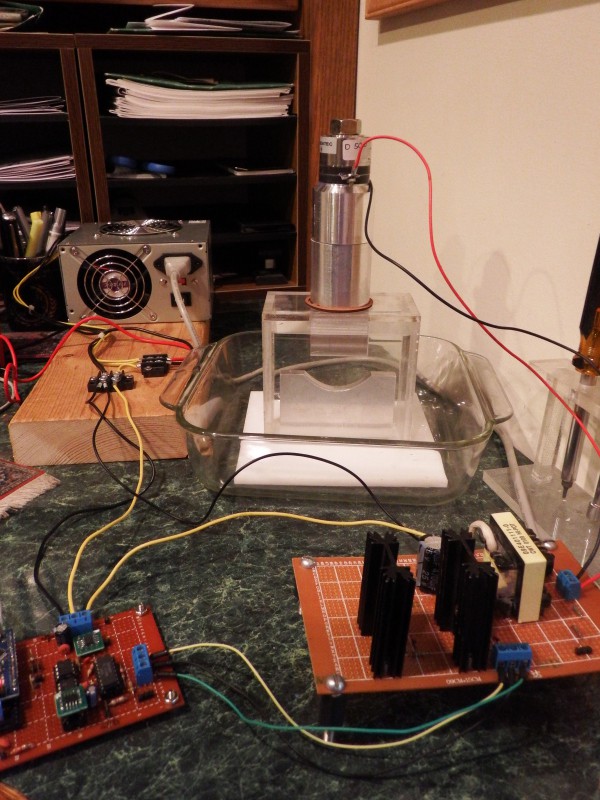
Her's a picture of the setup. The laptop controls an Arduino via serial port, and a small interface board (hanging from the transducer wires) interfaces the Arduino to the transducer.
Measure, unplug, make a pass, replug, and remeasure. It's pretty simple.
![]()
![]()
-
Final stretch begins
07/07/2015 at 21:11 • 1 commentTL;DR: First attempts at Ammonia production will begin in a couple of weeks.
I hope to have everything done and making first attempts at Ammonia production by August 17th, the Hackaday entry cutoff.
LEFT TO DO:
.) See if the power output can be tuned to a sin wave
.) Clean up/finish the power output board
.) Minor improvements to the controller board
.) Schematic capture/board layout of complete system
.) Get PCBS made for power supply
.) Final assembly of Ammonia production system
.) Make power supply plug/interface for mass flow controller
.) Make a couple of demo videos
Secret System
![]()
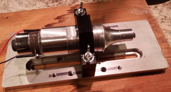
Here's a sneak peek at the the secret system.
The whole purpose of this Hackaday prize entry is based on these two pieces.
How are they used? What are they for?
All will be revealed in a couple of weeks.
Updated resonance program
![]()
The next big project step is to get a tuned horn, so I spent some time updating ResonanceFinder to make this task easier.
The new version keeps and displays the previous 10 sweeps - now it's easier to see how the response changes during the tuning process. I also added some minor improvements and organized the directory better.
(The X-axis labels are messed up. That's apparently a bug in the graph library I'm using - I'll look into it later.)
CNC mount for Transducer Horn
![]()
For proper resonance, a horn needs to be 1/2 wavelength long. Knowing the frequency of the transducer (28 KHz) and the speed of sound in Aluminum (5100 m/s) that comes out to about 91 mm of length.
In practice you always make the horn longer than needed and repeatedly shorten it while measuring the response. This usually involves many chucking and unchucking steps as you switch between lathe end-cuts and measurements.
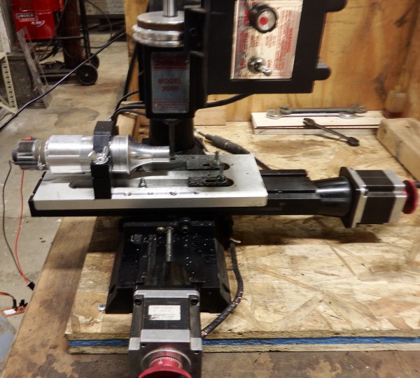
The horn has a node 1/4 of the way along its length which doesn't vibrate during the measurement process. It occurred to me that I might be able to clamp the horn at that point and measure the resonance while mounted on a CNC mill, so I made up a mounting clamp.
If this works it will greatly reduce the effort needed to tune the horns. Testing/horn tuning starts tomorrow.
Updated resonance circuit
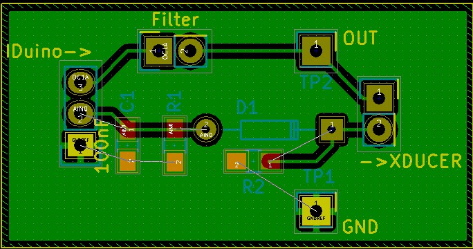
I added some convenience features to the interface circuit that sits between the Arduino and transducer, captured the schematic and made a board layout (and did some reorganization and administrivia).
The tuning circuit isn't worth having a board made, but I routed the PCB just in case someone doesn't want to hand-wire one. See below.
All files will be available on GitHub after the contest: source programs, CAD files for mounts and holders, circuit schematics and board layouts, and documentation.
(I'd make everything available now, but I'm putting off tasks that doesn't directly contribute to the prize until afterwards.)
![]()
![]()
Miscellaneous
Someone at my hackerspace makes mass flow controllers for a living... and gave me one! (Woot!)
This is/was the final piece of the system I was looking for. All that's left is putting things together and getting them to work.
Thanks Dave! You're awesome!
-
Software, and hand-soldered prototype
06/24/2015 at 04:12 • 0 commentsNew board, 9000 lines of software, resistive load, drill-press frame.
I managed to pick up a bug which slowed me down a little this week. Just wrote software and did a few minor tasks.
Someone at my space works for Linear Technologies (!), and knows LTSpice (!), and is an electronics designer, and has agreed to help me simulate the driver board and adjust it for clean output (!!!). When he comes back from vacation, in about 2 weeks. Woot!
Sorry for the haphazard placement of images and text. I'm finding that it is nigh impossible to predict what the Hackaday.io system will show after something is published. It's not WYSIWYG - things change after posting.
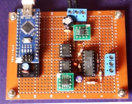
![]()
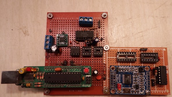
I made a "soldered" version of the control board. I'm hoping everything fits in a 4"x4" area, so that an ATX PSU case can be the project enclosure. Note: socketed Nano can be removed and used for other projects. I think I'll make that a part of the board design.
Remaining tasks:
a) Tune the driver board for clean output
b) Finish schematic capture of version 1 design
c) Board layout
d) Get some boards made
![]()
I had some leftover I/Os on the Arduino Nano, so I decided to add some features:
a) Two digital inputs, which can be linked to the transducer by user commands: on/off control, triggered on-time, ESTOP, and so on.
b) Two digital outputs, which can be controlled by user command or linked to system functions (ie - "on" when transducer is on)
c) Two LED outputs which show system state
d) I'm thinking of adding a sonalert, so the system can beep when the xducer turns on.
e) The extra I/Os will be optoisolated, for robustness.
Other than these features, I can't think of anything else the system needs.
I've got 1200 lines of executable code (semicolon count) in 9000 source lines across 48 source files, all of which seems to work.
Remaining tasks (software):
a) Measure current usage and calculate power
b) Implement power tracking system
c) Code to implement the extra features mentioned above.
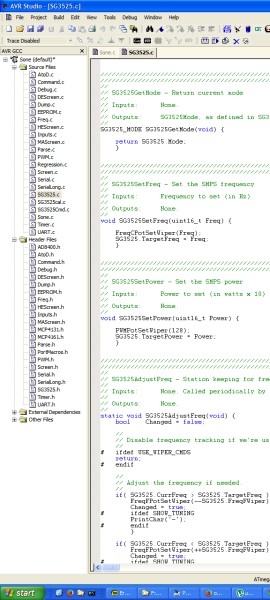
A friend gave me an old drill press frame, without the drill.![]()
I'm working up a new demo of the system in action - plastic welding or liquid mixing.
Here's the 50-watt transducer mounted.
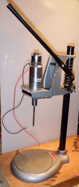
I found a 25Ω 50W power resistor in some equipment that was being thrown away at the space. This will make a good resistive load substitute for the transducers. I can attach this to the driver board and see which noise is coming from the driver circuit versus back-EMF from the transducer equivalent circuit.![]()
Here it is, mounted on some standoffs for heat dissipation.
-
Controlling analog systems with digital pots
06/15/2015 at 22:02 • 0 commentsQuick Summary
1) Arduinos can only generate 28kHz signals to a resolution of 120 Hz. That's not enough for this project.
2) Using digital pots to control analog systems is totally feasible.
3) A simple control algorithm can get a resolution of ±2Hz.
3) An algorithm based on control theory might be even more accurate.
Arduino generated signals have poor resolution
This project uses PWM signals in the ultrasonic range, around 28kHz. Since the transducer gets warm in operation, the resonant frequency changes which causes variations in the delivered power. For a consistent power output (and to prevent burning out the transducer) the system needs to adapt to these changes and make appropriate adjustments.
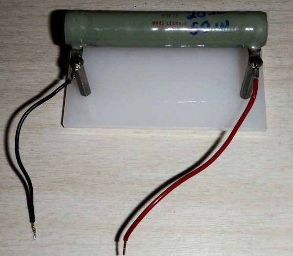
An Arduino can generate a repeating signal by connecting the CPU clock to an internal counter: every N CPU clocks the output changes state, making a square wave on the selected pin.
![]()
For Arduinos running at 16 MHz, this won't have enough frequency resolution. Taking 32kHz as the upper bound the output-compare counts 512 system clocks per cycle, and you have to change the output pin twice in each cycle so the output compare needs to count to 256 for each pin change.
![]()
A table of counts and generated frequencies shows that this method doesn't have a lot of frequency resolution. Going from one count to the next changes the output by about 120 Hz, or 1%.
That's not a lot of resolution.
![]()
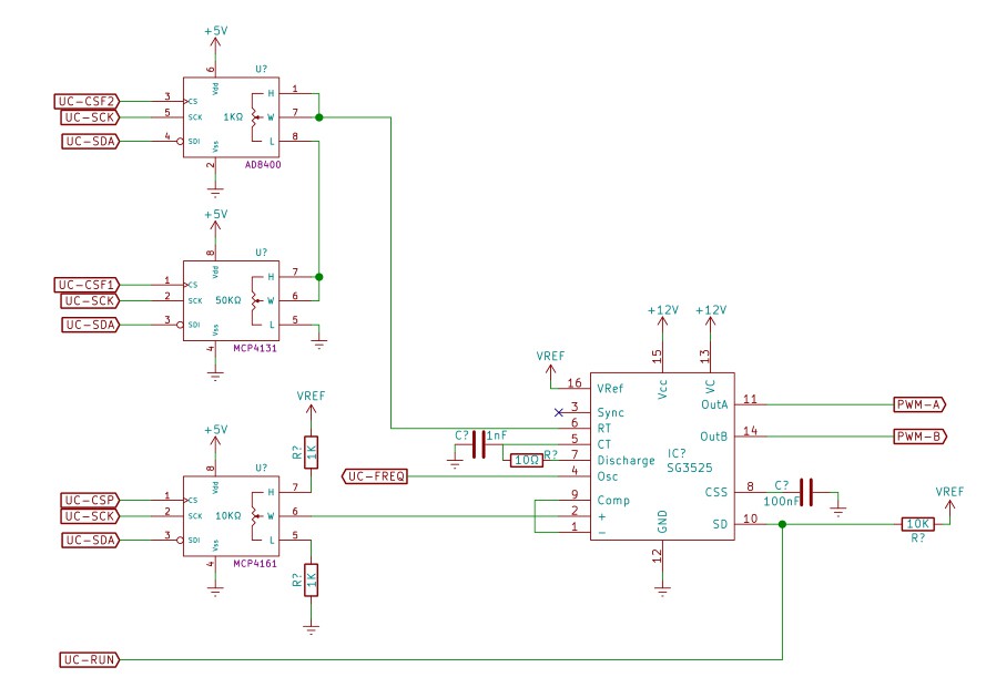
So for the transducer project I decided to try controlling an analog signal generator using digital pots. The UC3525 is essentially an RC oscillator with a pulse width generator, both of which can be controlled by a fixed resistance.
A digital pot typically has 128 or 256 positions, and is "set and forget" from the microcontroller. This frees the micro for other tasks such as power monitoring and user input, and also simplifies the control software.
![]()
Having 256 steps is still not enough resolution for the frequency range needed (I want to sweep from 20kHz to 32 kHz), but the range can be extended using two pots in series: a coarse setting of 50kΩ in series with a 1KΩ fine setting gives effectively 3Hz resolution on the frequency setting.
ResultsI was surprised at how well this actually works.
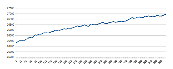
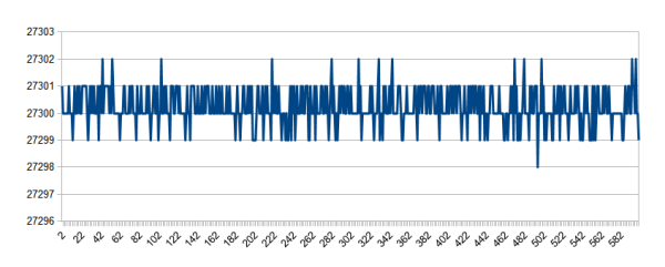
The first image below shows the free-running (ie - no feedback) system for the first 10 minutes at startup. The frequency drifts higher over time, presumably due to components warming up. After warm-up the system shows slight variations over time, as seen in the second image. Considering that an Arduino-generated output will have a resolution of 120 Hz, the 150Hz variation over 10 minutes seems reasonable.
![Frequency drift at startup]()
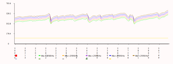
![]() The previous images had no feedback control from the micro. With the controller measuring the output and adjusting the pots the variation in frequency becomes much less. In a 10-minute stretch of output the 1-second counts show a remarkable accuracy. The microcontroller adjusts the resistors 25 times each second, so the frequency will be high or low in any specific time slice, but the overall accuracy (total pulses per second) is quite accurate.
The previous images had no feedback control from the micro. With the controller measuring the output and adjusting the pots the variation in frequency becomes much less. In a 10-minute stretch of output the 1-second counts show a remarkable accuracy. The microcontroller adjusts the resistors 25 times each second, so the frequency will be high or low in any specific time slice, but the overall accuracy (total pulses per second) is quite accurate.![]()
Setting the system to bump the frequency by 1 Hz shows a similar accuracy.
![]()
The feedback/control algorithm is a simple bang-bang control that increments or decrements the fine control pot as the measured frequency is below or above the setpoint.
A proper PID control system would probably have even more accuracy.
So in summary, microprocessor control of analog systems using digital potentiometers seems to work. It's a viable technique that could be used to control many types of analog systems.
-
Using the UC3525 pulse width modulator
06/08/2015 at 18:55 • 0 commentsFor my project I'm building a high voltage ultrasonic power supply (400V, 28kHz) based on the UC3525 pulse width modulation chip.
There's very little information on the net that explains how to use these chips, so for this week's update I thought I'd write a quick summary.
Where to get 3525 chips
Pulse width modulators are common. They're made by TI (UC3525), ON Semiconductor (SG3525), Fairchild (KA3525), and several others. They're available from DigiKey, Mouser, and from eBay in small quantities for about a buck each.
The datasheet for these chips contains almost no application information. Some have a small section detailing how the "Shutdown" pin can be used to skip a pulse when needed, but others don't even have that.
The internet isn't much help either. Tahmid's blog has a pin-by-pin functional description with a demonstration circuit, and the SG153x App Note describes a related chip, but with important differences.
If you don't understand something here, take a look at Tahmid's blog for a counterpoint explanation.
Also, Open Impulse sells an SG3525 experimentor's board for $3.24 which includes potentiometer controlled PWM and frequency.
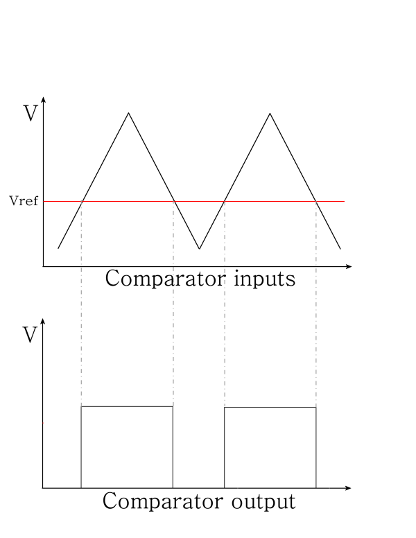
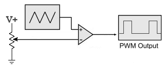
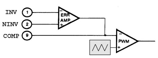
Generating PWM signals
A PWM signal is generated by comparing a triangle wave to a reference level. The output will be high when the triangle is higher than the reference and low everywhere else. Adjusting the reference adjusts the pulse width.
![]()
![]()
The UC3525 chip is basically a triangle wave generator and comparator, with some extras thrown in for convenience. Any properly-scaled voltage proportional to output error can be used as a reference voltage to the comparator. A larger error results in a higher reference voltage, which clips the triangle wave higher, which makes the output pulses narrower, which generates less output, which in turn generates a lower error voltage.
For example, a 12V power supply might have an error voltage proportional to the difference between 12 volts and the actual output. The voltage will shorten or lengthen the PWM times, forcing the output to exactly 12 volts.
The circuit doesn't have to be a power supply, it only needs a feedback voltage proportional to the error. To run a DC motor at a specific speed, simply feed back a voltage proportional to the difference between the requested speed and the actual speed: negative feedback will force the motor to the right speed.
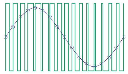
So for another example, you can make a class-D amplifier using an audio signal as Vref:
![]()
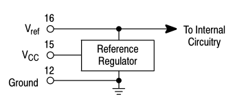
Precision voltage source
![]()
The UC3525 supplies a precision 5.1V reference which can be compared to the error signal, or as a 5V supply for external logic (up to 20mA).
So to make a regulated power supply, simply divide the output down using 1% resistors and compare it to the voltage reference and you're done. For other circuits, simply generate 5.1V on correct output, with higher voltages for "too much" output.
An example from Tahmid's blog:
![]()
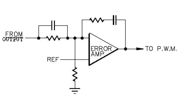
Error Amplifier
The UC3525 implements an extra op-amp on the VRef input of the comparator and brings the connections out to the user. This makes it easy to convert error signals - the positive input can level shift, while the inverting input and feedback can amplify the error to bring it into range.
![]()
You can also use the op-amp to slow down the feedback. In the circuit below, the PWM error adjustment is delayed by the RC constant of the amplifier feedback. This can eliminate ringing and spurious oscillations that you might get from instantaneous feedback.
![]()
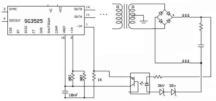
If your output has a lot of inertia (big filter capacitors, motor speed, or similar), you can run the PWM in ON/OFF mode with an optoisolator. The control circuit is then isolated from the output.
In the example below, when the output is higher than 68 volts the optoisolator turns on, comparing the full Vref against Vref/2 and the PWM turns off. For a lower output voltage, the optoisolator is turned off and 0 volts is compared against Vref/2, turning the PWM completely on.
![]()
Triangle wave oscillator
So a natural question to ask is: how does one generate a triangle wave?
You start with a constant current source. Then you connect the constant current source to a constant capacitance and the voltage rises linearly as a function of time.
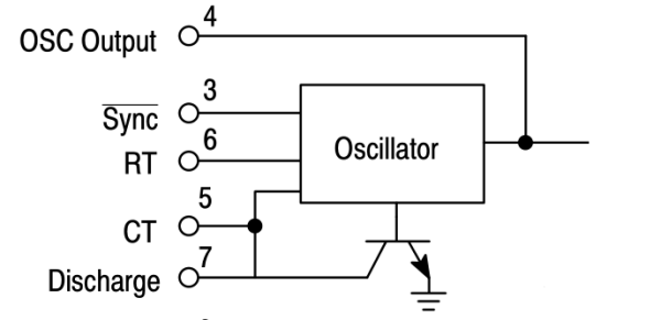
The UC3525 provides a constant current source and a flip-flop mechanism that alternately charges and discharges a capacitor which the user supplies. The user also supplies an external resistor which sets the amount of current.
The upshot is that the user sets the oscillation frequency by supplying an R and C to the oscillator section according to the following formula:
Note: the UC3525 has two outputs each modulating half-cycles of the output frequency. This means that the triangle oscillator runs at *twice* the output frequency (one output for each half cycle). If you want a 50Hz output, configure the oscillator to run at 100Hz.
The discharge resistor, Rd is discussed later.
The oscillator has a pulse output that can be used to measure the generated frequency, and an input for synchronizing multiple devices.![]()
To synchronize two devices, set the "master" device to oscillate at the desired frequency, set slave to oscillate a little slower (for example: 90% of the master speed), and connect the "OSC Output" of the master to the slave "nSync" input.
Clock pulses on a slave nSync prematurely cycle the oscillator flip-flop - causing the peaks and troughs to synchronize with the master.
As far as I can tell, no one has ever used this feature. If you don't need to synchronize multiple units, just leave the nSync and OscOut pins unconnected.
Programmable Dead time
![]()
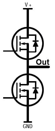
A "totem pole" output can have problem with synchronous control pulses.
The power transistors don't turn off instantly when their controlling pulse goes low, so if the falling and rising edges of the control pulses are close enough, there's a brief time when both transistors are conducting.
This is called "shoot through", and in effect the transistors briefly short the power supply to ground, often with disastrous results. Usually this ends up burning out your vary-expensive output transistors.
Conceptually, the gate has a small capacitance and the driver has an internal resistance, so switching the transistor takes an RC constant to complete. Other factors also come into play, such as the lead and trace inductance.
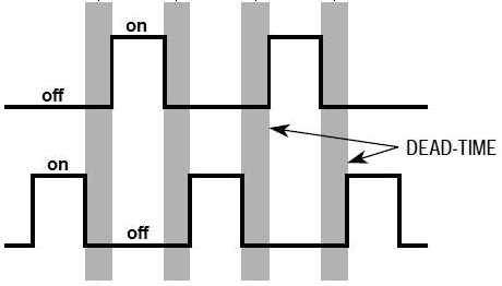
The solution is to have "dead time" where both pulses are off during the transitions, giving the active transistor time to turn off before the inactive one turns on.
![]()
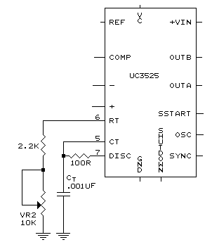
The Rd in the UC3525 oscillator section allows the user to set a dead time.
The rise time of the oscillator is determined by Rt, but the fall time is determined by the sum of Rt and Rd. The extra conductance causes the capacitor to discharge faster than it rises, prematurely ending the pulse a little before the opposite pulse begins. The end result is that there is a short time when both pulses are "off" at the same time.
If you don't need dead time, short the "Discharge" pin directly to Ct, making Rd effectively zero.
Here's a variable frequency example with 8 uS dead time. See the datasheet to determine dead time per component values.
![]()
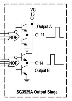
Output drivers
![]()
The UC3525 output is itself a totem-pole: each output can source or sink about half an amp of current (varies with vendor - see datasheet).
The output voltage comes from a supply separate from the internal chip logic, so you can interface the PWM sections with low-voltage logic while switching a much higher voltage. For example, high power FETs usually require between 8 and 20 volts for proper switching. You can operate the UC3525 logic from a high voltage input, 35 volts for example, while switching a lower voltage more appropriate for the FETs.
If you don't have need for separate voltage levels, just connect Vc and Vcc together. The UC3525 logic operates anywhere from 8 to 35 volts.
Soft start and low voltage
The UC3525 has a couple of other features which are straightforward to use.
A capacitor connected to the "soft start" input will delay startup during powerup. This prevents the device from generating spurious output before other sections of the circuit come on line. It can give a microcontroller a chance to boot, capacitors a chance to charge, and other control electronics time to start.
There's also a low-voltage detection that takes the outputs offline when the power is removed - you don't have to worry about the output going haywire as the control circuitry powers down.
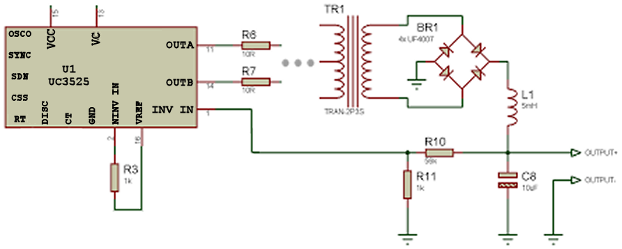
Putting it all together
![]()
With all these features there's a lot going on in this one chip, but it's mostly passives programming the individual sections. Once you understand the individual sections, using the UC3525 in a circuit is straightforward.
Here's an example of a completed project from the links posted above, and the one on which I based my design. It's pretty simple, and can be breadboarded in an afternoon.
Once you have the basic circuit running, modifying it for your project is straightforward.
-
Status for June 02
06/03/2015 at 01:28 • 0 commentsCurrent status:
1) Software development of the controller board is coming along
2) Measuring frequency and pulse width on an Arduino at 30kHz is a hard problem
3) ...but I think I have it sorted with some additional hardware. Adds a dime to the build cost.
4) I've built a gas collection system
5) I can generate (and collect) Hydrogen and Nitrogen as needed for the project.
6) I'll soon start building the cavitation system
I was busy with personal obligations, so abbreviated report this week.
The driver and controller board are working well enough that morphing them into a mature hacker-friendly project is straightforward, and this can happen over June and July at a more leisurely pace. Further updates will probably say "nothing of interesting going on", except for the occasional demo.
Time for some chemistry!
I built Nitrogen and Hydrogen generators, as well as a gas collection system. My plan is to generate 1.5L of Hydrogen and 0.5L of Nitrogen, giving 2L of the correct ratio of gases for experimentation. Two litres (at a time) should be plenty for near-term experiments.
Here's a video of the system generating Nitrogen:
Improve the Haber process
See if ultrasonic cavitation can be used to fixate atmospheric Nitrogen less expensively than the Haber process.
 In a
In a