 x-labz
-
1Step 1
Order the components
Order the components listed in the BOM (bill of materials)
Additionally you will need some more components for the programming adapter:
Mouser ID 538-78864-1001 649-54202-G3003LF ![]()
-
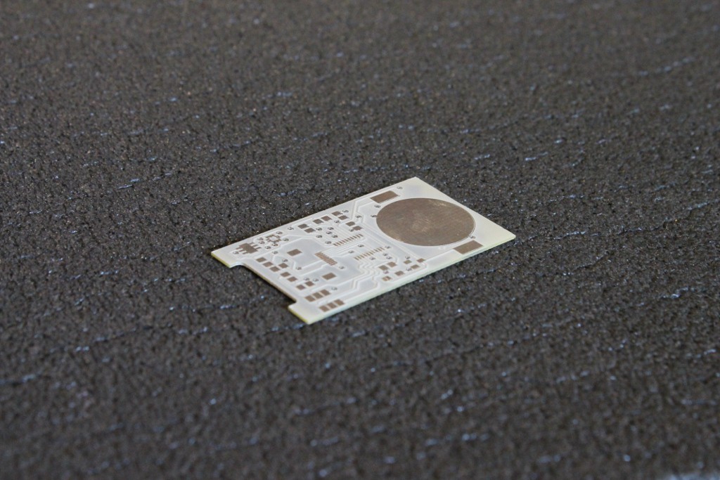
2Step 2
PCB
Order the PCB for the main circuit and for the programming adapter; don’t forget, that they should be 0.5 mm thick! Otherwise it will not fit in the case.
![]()
Programming adapter
-
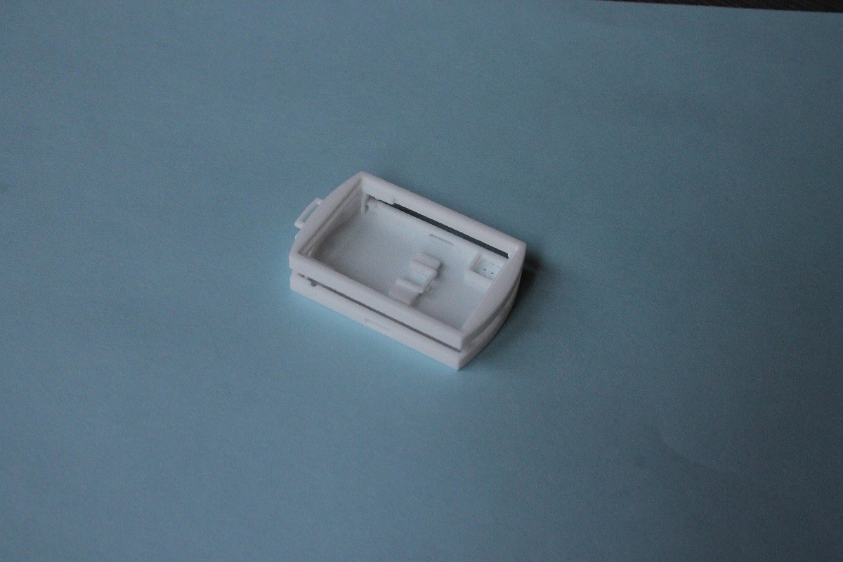
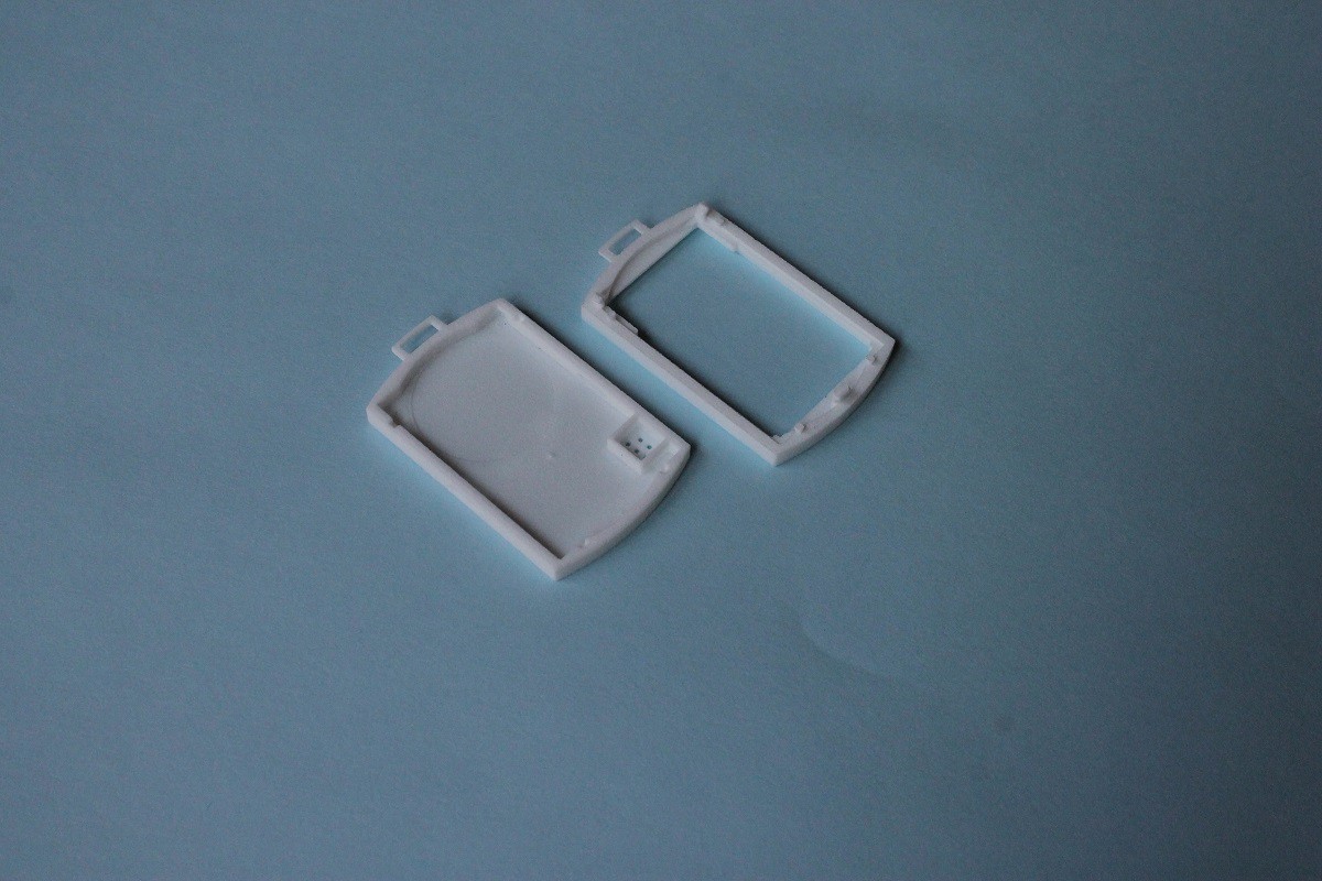
3Step 3
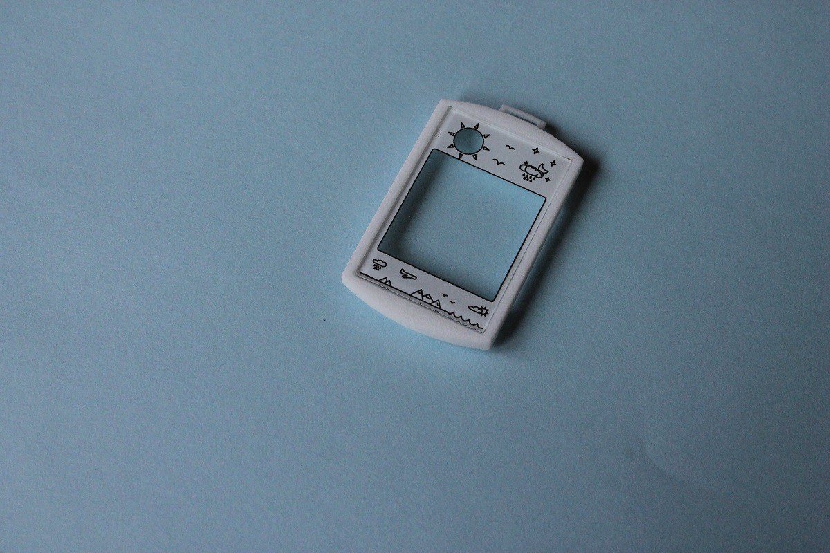
CASE
Get the case and the programing adapter clip 3D printed. For the best result use SLS technology, e.g. “Strong and flexible” nylon material at shapeways.com
![]()
The parts of the case are connected with thin plastic strings, separate them using a sharp knife or scalpel.
![]()
3D printed programming adapter clip
-
4Step 4
-
5Step 5
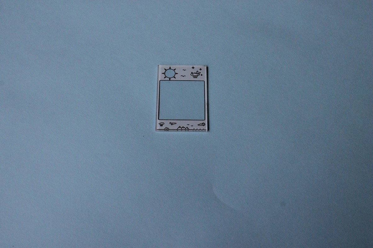
Print mask & graphics
The mask and graphics should be printed on the plexi cover. Use an appropriate printer, e.g. UV cured ink in special printer designed to print on solid objects.
The graphics layer should be printed first, then the cover mask layer.
![]()
-
6Step 6
Assembling cover
Carefully glue the plexi cover in the upper side of the case. Use some kind of non aggressive glue.
![]()
According to experiments, superglue and mosaic glue will burn the ink on the plexi cover, so don't use these.
-
7Step 7
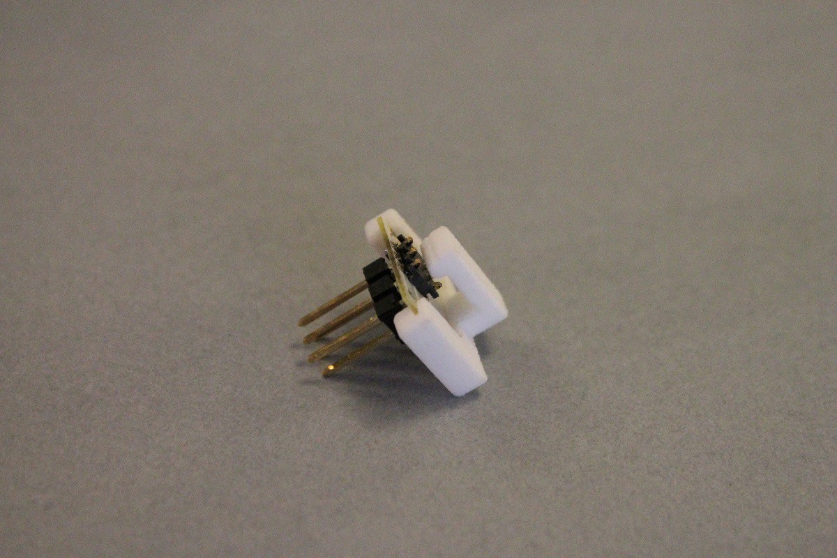
Programming adapter
Solder the programming adapter components to the programming adapter PCB.
Insert the adapter PCB into the 3D printed clip.
![]()
-
8Step 8
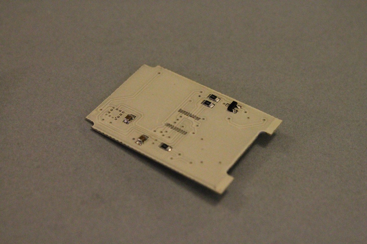
Soldering the components I.
Solder the following components:
- passive components, resistors, capacitors (C1,C2,C3,C4,C5,R4,R5,R6)
- Diode (D1)
- MOSFET (Q1)
- Battery holder
Install a CR2016 battery, test that the 3V voltage appears on the test point. (C1+)
![]()
-
9Step 9
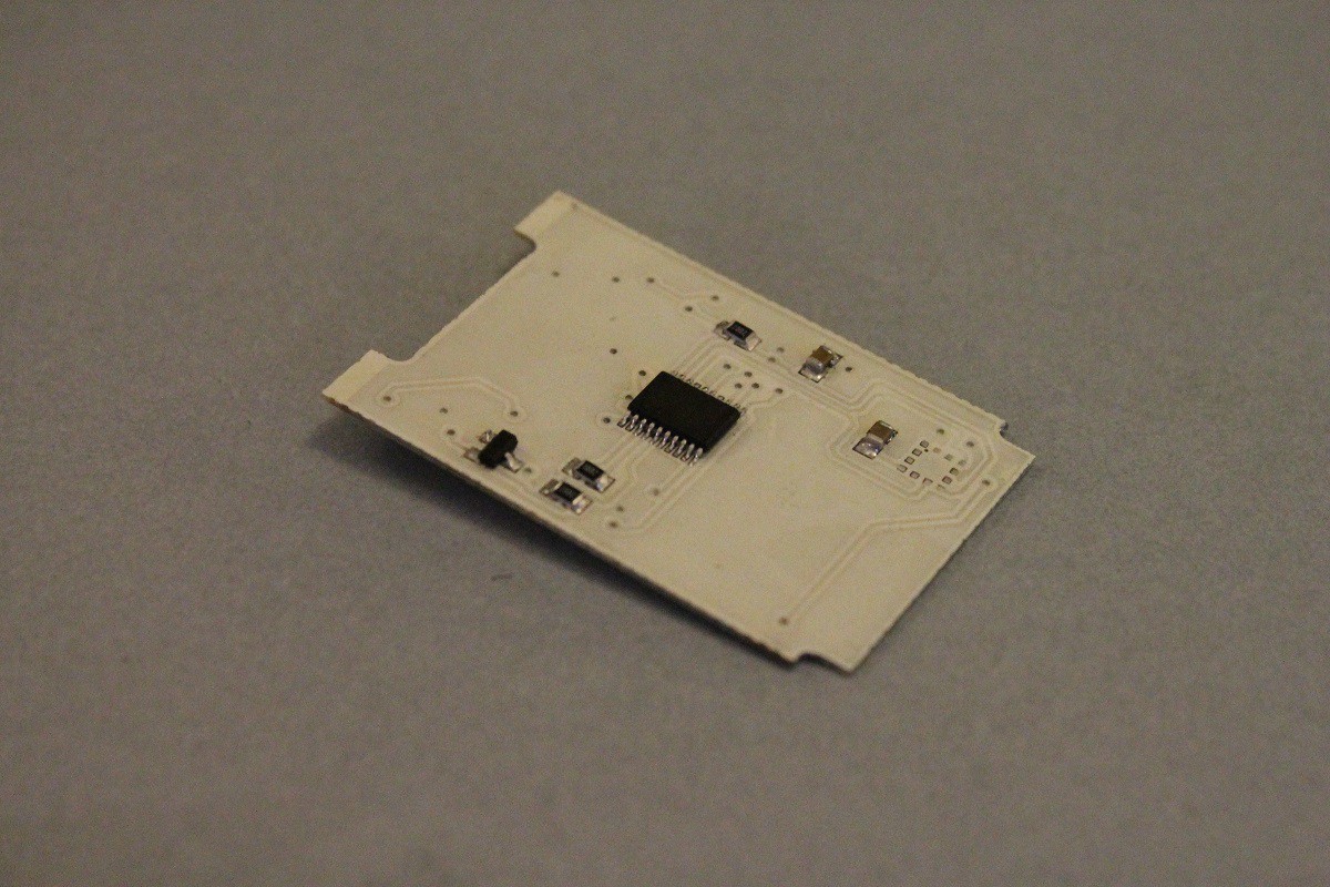
Soldering the components II.
Remove the battery.
Solder the following components:
- FPC connector (FPC10)
- AVR MCU (U3)
Install the battery, check there is no short circuit, the 3V should be measured on the test point. (C1+)
![]()
-
10Step 10
Programming the MCU
Connect the custom programming clip, then connect the ATMEL ICE ISP programmer. Be sure that the polarities are connected correctly.
Install the battery.
Download the firmware using Atmel Studio.
You can check the ~60 Hz square wave signal on the test point. (AVR leg 4)

Discussions
Become a Hackaday.io Member
Create an account to leave a comment. Already have an account? Log In.