 x-labz
-
11Step 11
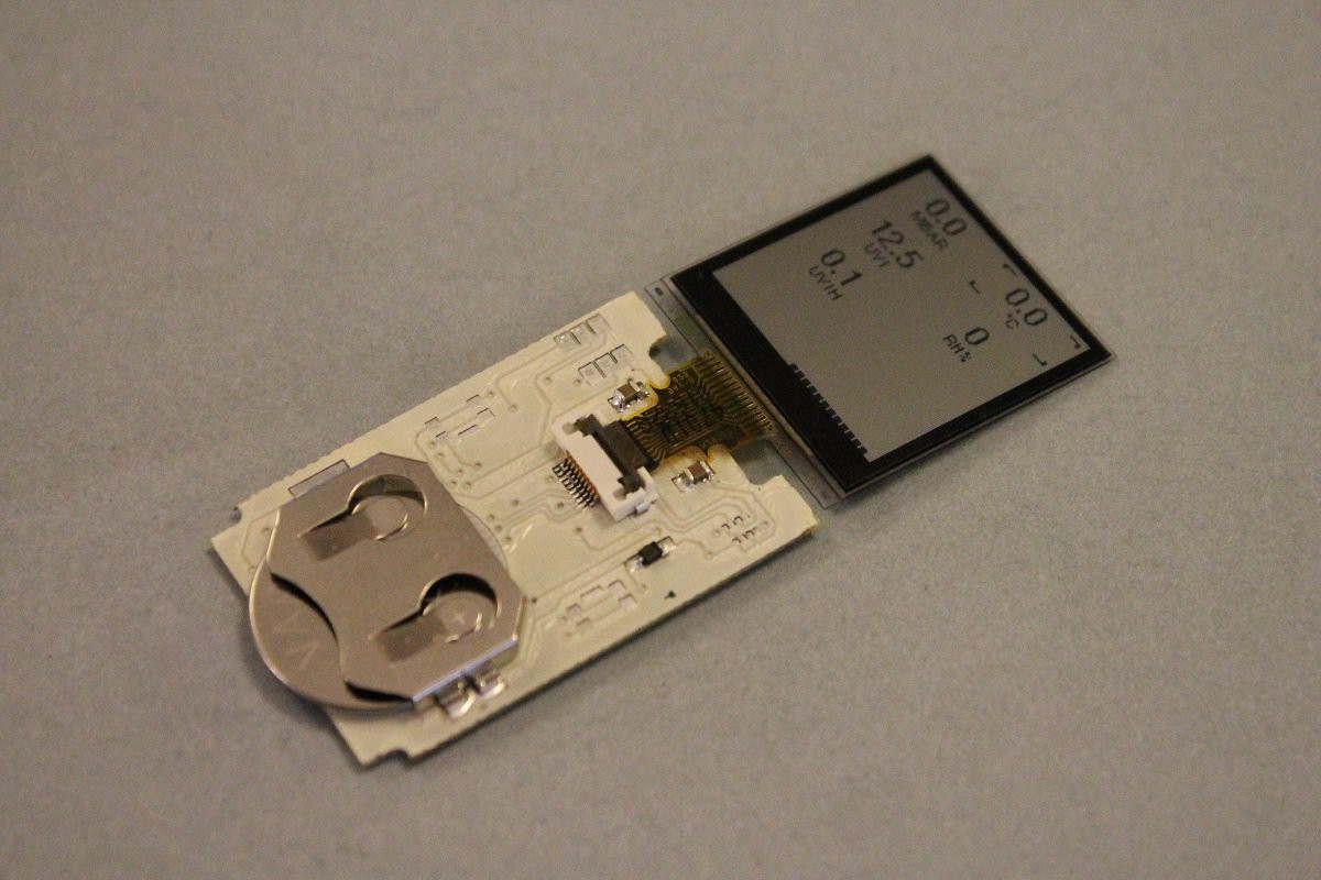
Connect the LCD
Remove the battery.
Connect the LCD display in the FPC connector
Install the battery; the LCD should display readable numbers.
![]()
-
12Step 12
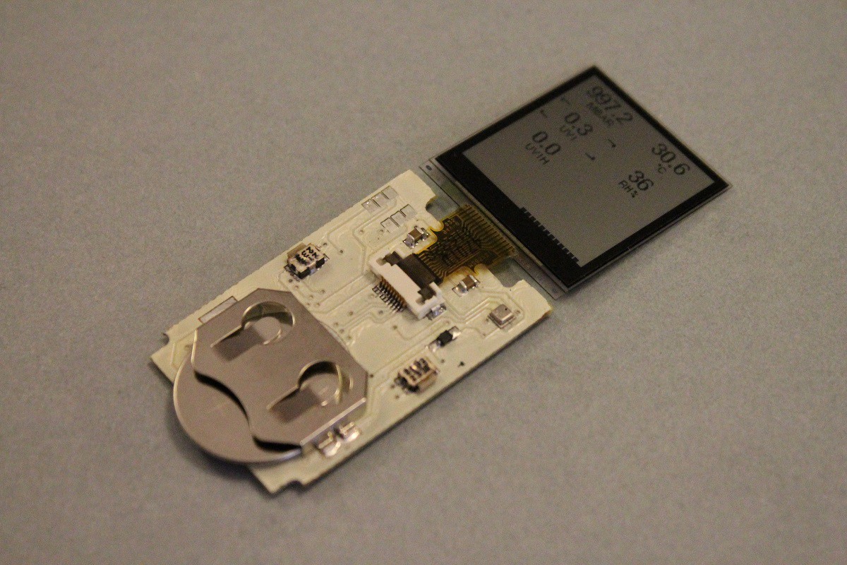
Solder the sensors
Remove the battery.
Solder the rest of components. The sensors should be soldered with reflow technology.
Install the battery, the LCD should display reasonable values. Check the operation of the tactile switches.
![]()
-
13Step 13
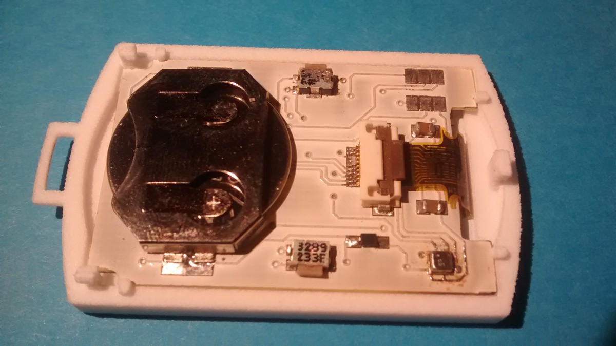
Final assembly I.
Install the LCD, and the main board in the upper side of the case; the LCD should fit in it’s place. The PCB will be kept in place by the small grips.
![]()
-
14Step 14
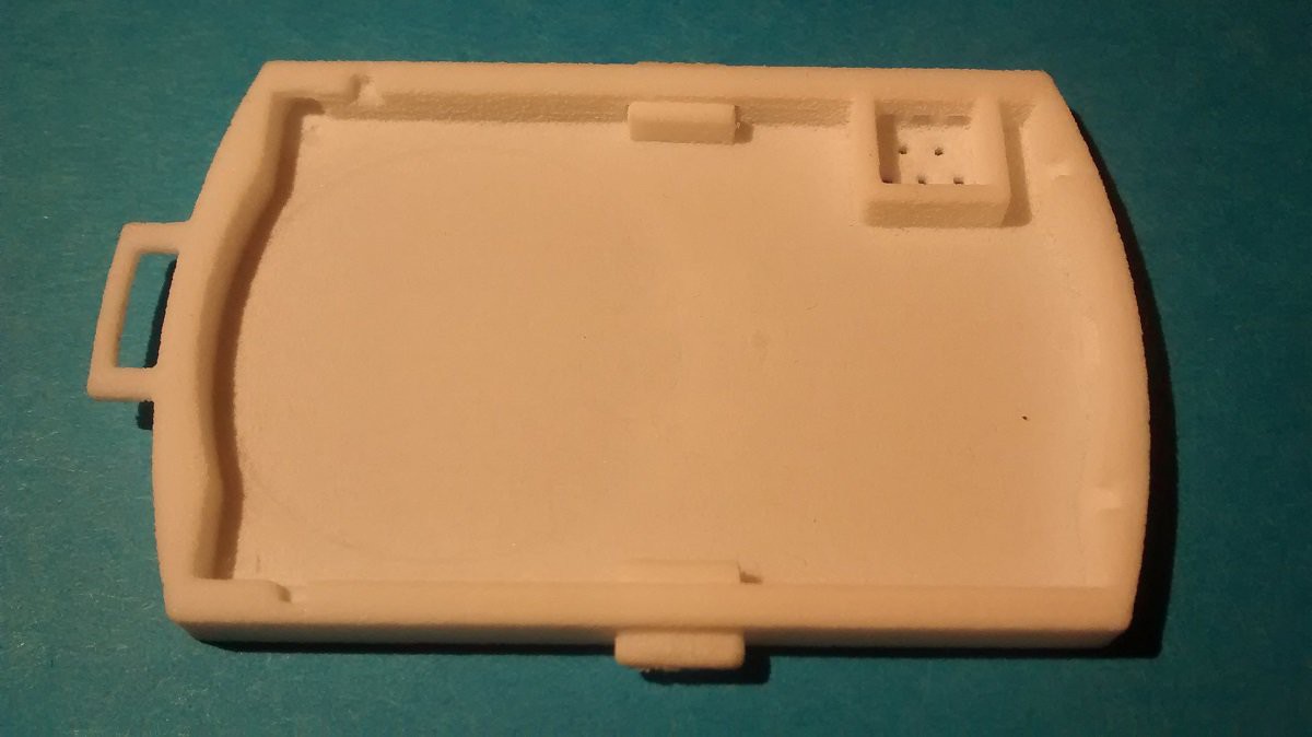
Final assembly II.
Install the buttons into the bottom side of the case. Carefully push the top and bottom parts together, paying attention to the position of the buttons.
![]()
-
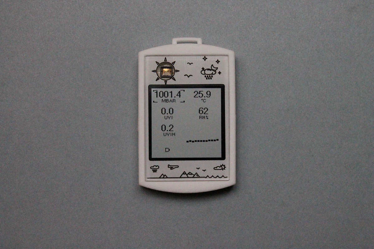
15Step 15
The Result
![]()
Discussions
Become a Hackaday.io Member
Create an account to leave a comment. Already have an account? Log In.