lion mclionhead
-
Anything but Matlab
02/10/2018 at 07:23 • 0 comments![]()
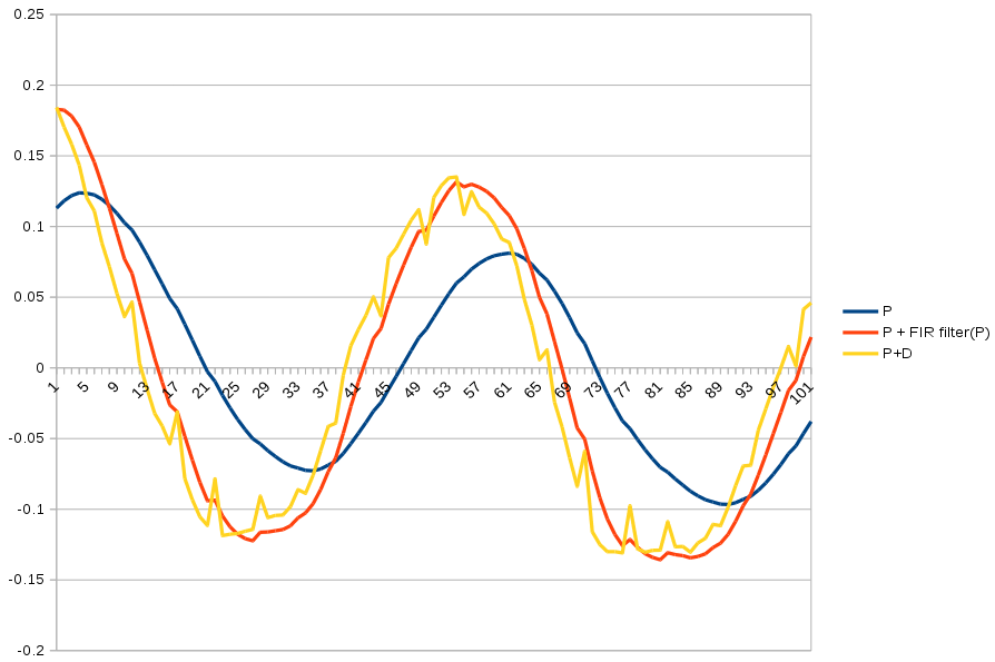
A student lion could derive FIR filters directly from laplace notation of AC circuits. Nowadays, all lions can do is look it up on kiwipedia. Using actual driving data recorded on the Odroid, the highpass filter was a more delayed & smoother version of the D feedback. The highpass filter needs the D scaler & a bandwidth from 0-1.
The highpass filter is:
y = bandwidth * (prev_y + input[i] - input[i - 1])
prev_y = y
The D in the original PD feedback fights all the frequencies of the input.
output = P * input[i] + D * (input[i] - input[i - 1])
If the (input[i] - input[i - 1]) is replaced by the highpass filter, the D now fights only high frequencies of the input.
output = P * input[i] + D * y
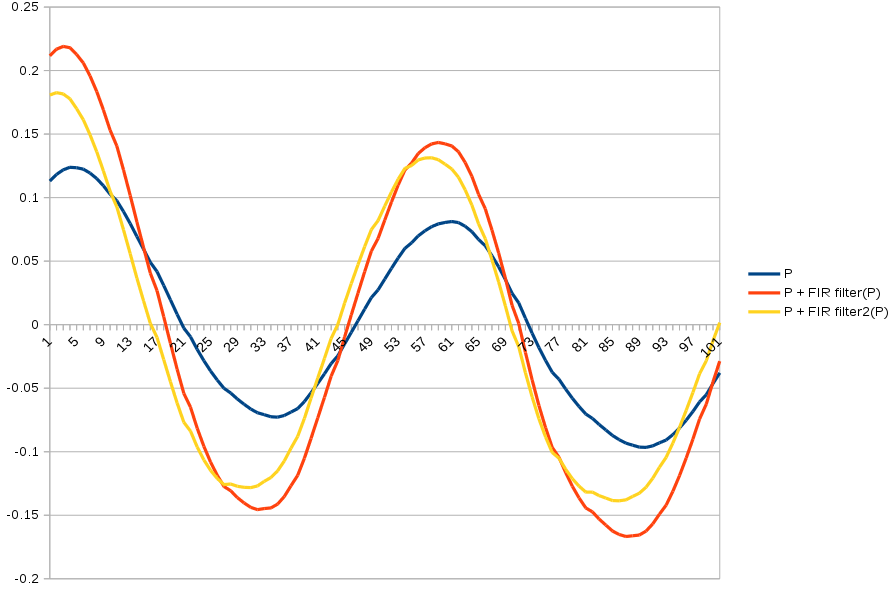
You get a sharper cutoff by stacking multiple highpass filters.
y = bandwidth * (prev_y + input[i] - input[i - 1])
y2 = bandwidth * (prev_y2 + y - prev_y)
prev_y = y
prev_y2 = y2
![]()
FIR filter2 varies much more greatly by bandwidth & gets farther ahead than the single order filter.
Kiwipedia has a complicated formula for calculating bandwidth, so lions just graph it until it looks good. It has to be 0.9 to 1.
-
Driving straight again
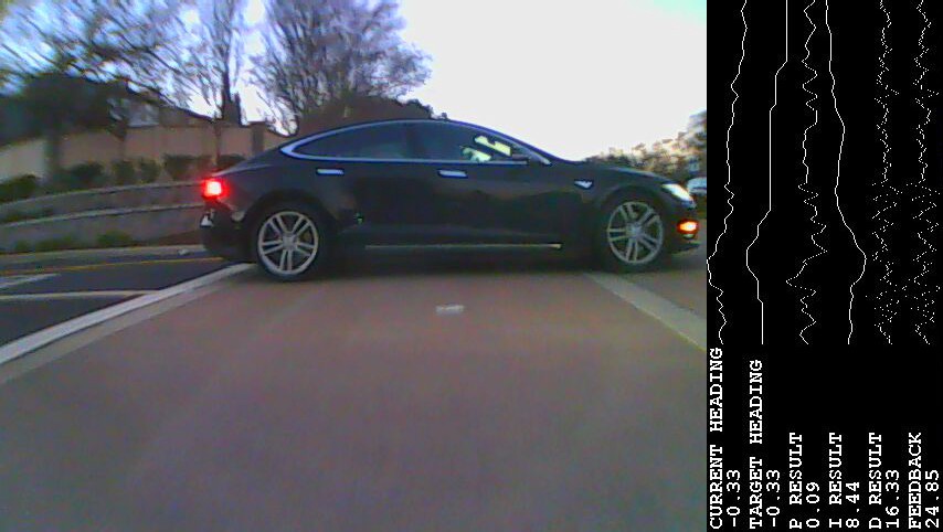
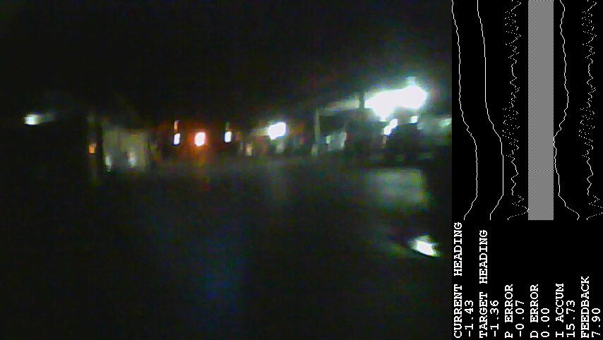
02/09/2018 at 03:56 • 0 commentsWith the D feedback debugged, it drove straight again for the 1st time since the CG was lowered. It also managed mostly straight driving with the mast & shirt, at 10mph, a particular challenge but critical for videos. Note how the D feedback lags the P feedback. It immediately counteracts the P feedback, once the servo starts taking effectiveness.
Feedback limits were worthless, as usual. The Odroid managed to not crash, today. Cleaned the battery contacts. Unfortunately, the battery died after only 7 miles. It faked straight driving by oscillating faster than before & spent most of the drive pushing the front wheels sideways. It's very expensive testing, since the tires are $40 per set.
![]()
![]()
![]()
Lots of junk heaps on Calif* roads.
-
Feedback notes
02/08/2018 at 07:24 • 0 commentsMy very 1st control problem was a magnetic levitator. Remembered from those days that in order for the magnetic levitator to be stable, they needed to highpass filter the hall effect sensor. In those days, they did it with purely analog circuits. Highpass filtering the sensor was how they overcame laggy actuators. It would be an interesting project to make different FIR filters & observe the effect on every feedback loop in the apartment, but a more promising solution appeared.
Manely, D feedback was never being computed. The bug started on Dec 7 2014 when the truck 1st started moving with an analog gyro. It was later switched to a digital gyro, but the source code still read an analog gyro reading of 0. Such is the importance of logging telemetry. It took a while to figure out the easiest way was an Odroid overlaying data points on video.
-
More steering tests
02/07/2018 at 08:48 • 0 commentsIt's a bit frustrating, since cheap commercial products have had heading hold forever. The problem is the vehicle was heavily modified for cargo. Without cargo, it's quite worthless.
The shock absorbers were removed. The suspension was lowered. More of the front wheels contacted the road & the steering rods push more indirectly. This made the steering rods less effective at pushing the wheels. Video has shown increased lag between servo & wheel is the single biggest reason for the oscillation.
In the stock configuration, a simple PID controller did the job as good as any commercial heading hold product. It only oscillated when carrying the heaviest, unsecured payload, so probably not a lack of programming ability.
Another run in which the Odroid repeatedly crashed & failed to record any useful data made some ideas start to gel. Try limiting P & D feedback while letting I feedback grow indefinitely. A more drastic idea is adding P error to a copy of itself which has been delayed by a certain fraction of the oscillation period. This is like applying a comb filter to the error.
Unfortunately, the customary mathematical descriptions of algorithms that detune oscillations from control loops are a bit beyond lion brain power. It seems the method involves highpass or lowpass filtering the error or some parts of the feedback, but the frequencies (poles?) control loops operate at can be confusing to someone used to filtering AC electrical waves.
-
Debugging steering with video
02/06/2018 at 06:46 • 0 commentsAs flimsy as it looks, the Odroid once again performed flawlessly, recording 96 minutes of video with data logging, as the vehicle bashed around & flipped over.
The mane thing it revealed was the sensor was working & the servo was getting the right feedback. There was no delay between the video & sensor. The video might have lagged the sensor because of the way the telemetry was buffered. The video showed the vehicle wasn't responding to feedback. In some cases, the vehicle responded by turning the opposite direction of the feedback. It tended to respond less over time, until on the final oscillation, it either didn't respond or it responded by going the opposite direction.
There were no anomalies with the I feedback. I accum & feedback are in the same units. What the PID controller deemed to be center is the I accum. All the cases showed I accum converging on +20. When feedback goes above I accum, it should turn left. When it goes below I accum, it should turn right. There's no obvious correlation between I accum & oscillation, only the P error & oscillation.
-
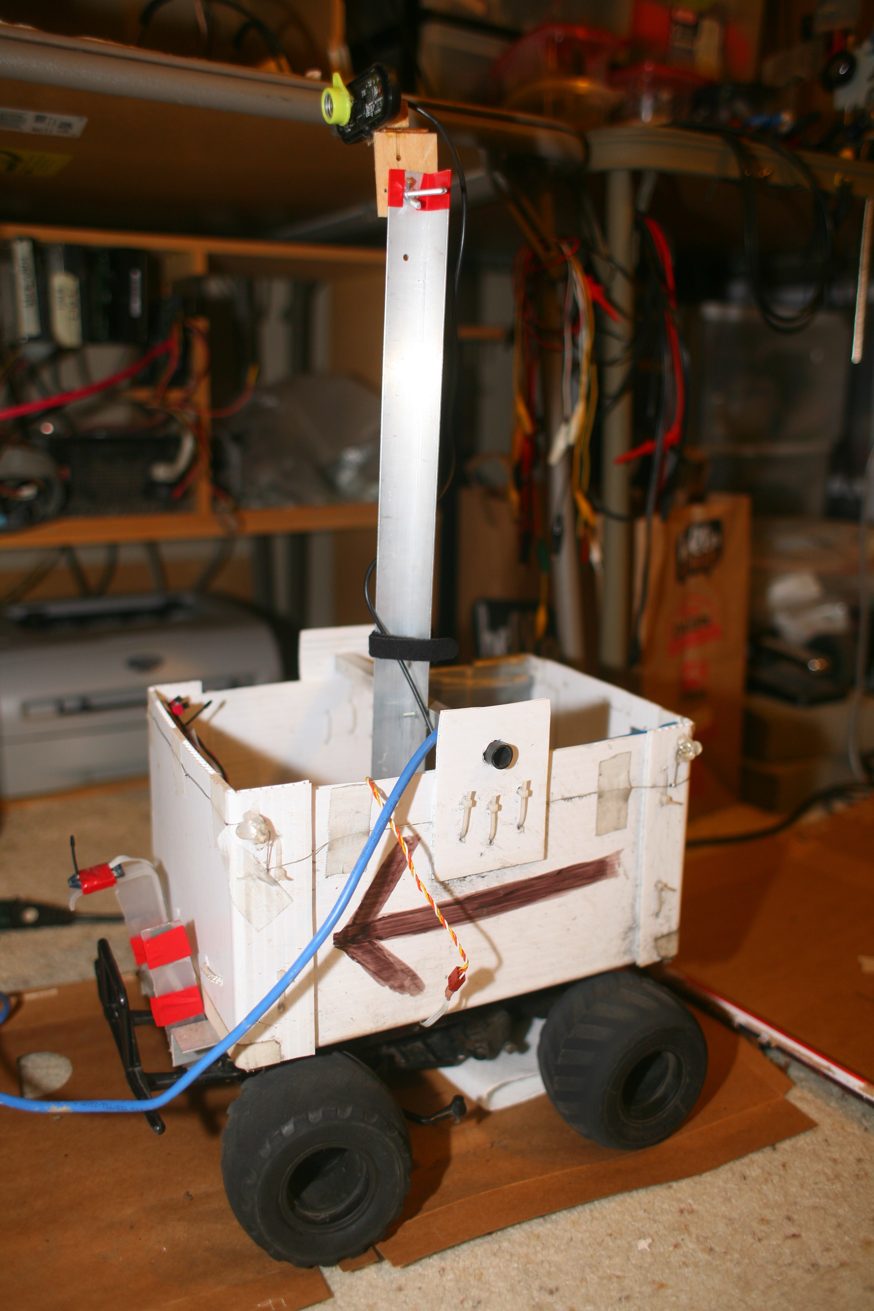
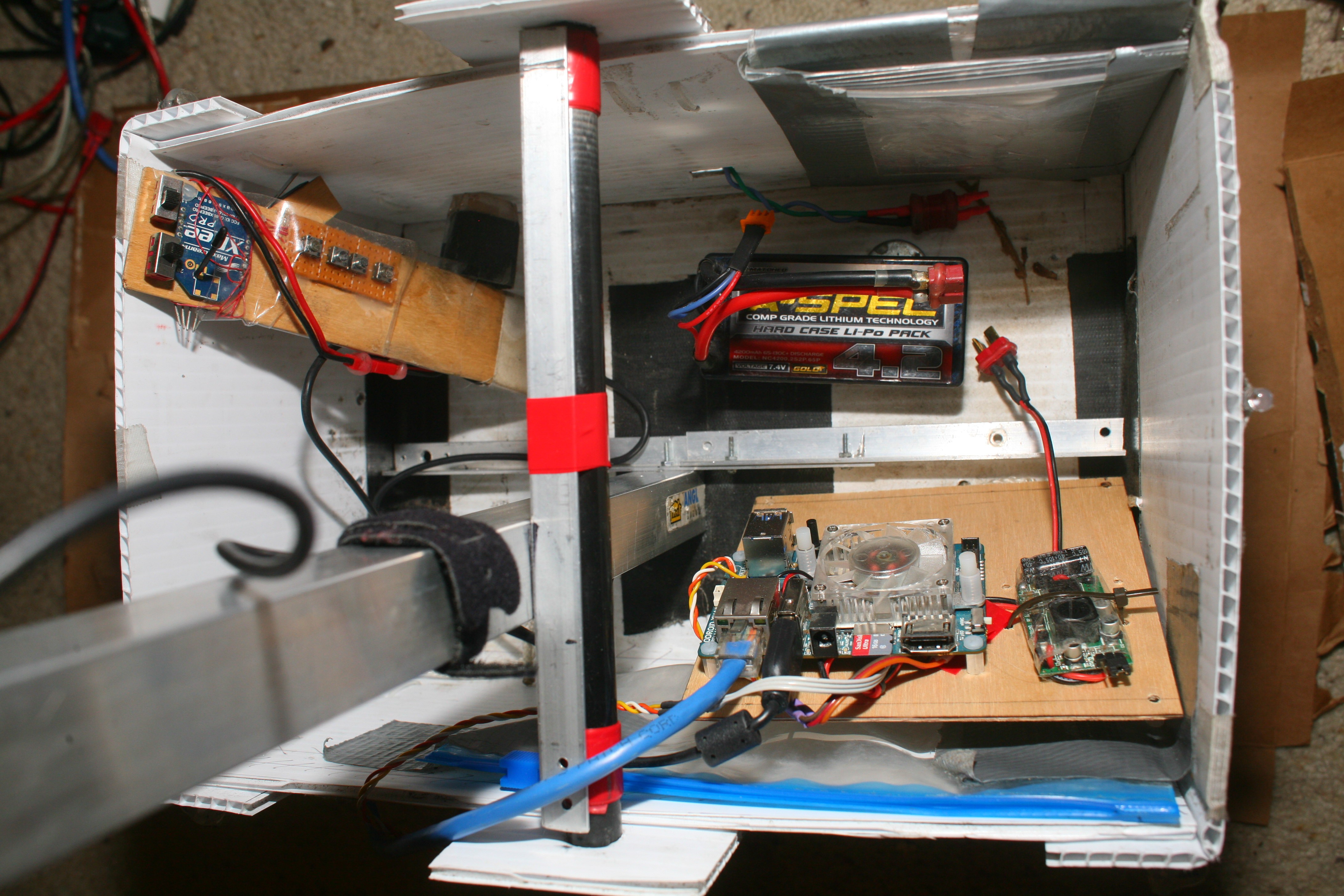
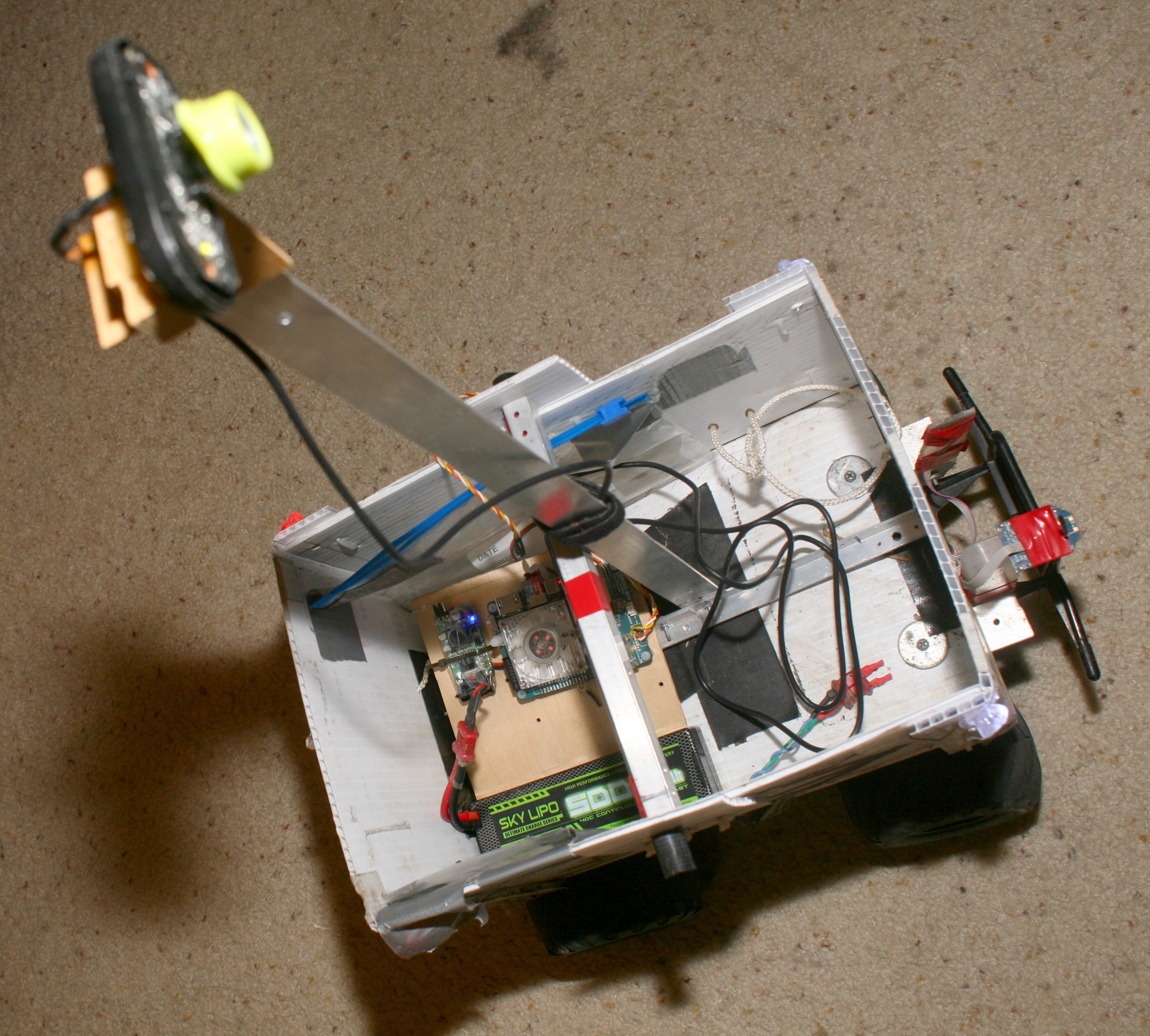
The Odroid is back
02/05/2018 at 08:06 • 0 comments![]()
![]()
Steering has been an immense problem. The best way to debug it has converged on overlaying as many data points as possible on a video stream. Getting just a minimal amount of video aided debugging information turns out to be an immense amount of work. 2 days of much debugging yielded something that seems to be reliable enough to handle the needs of recording telemetry in the field.
Ultimate running aid
Eliminate everything from running but the running part.