-
The SynthaSense Suit, Mark 2
05/13/2016 at 16:38 • 0 commentsI've been working on evaluating platforms for the Mark 2 version of the SynthaSense Suit. Yup, it now has a name. I have these requirements.
- It needs to be 32 bit
- The design of the system needs to be open sourced.
- It has to have an RTOS
- It needs to have a neural network
- It needs to be wifi and bluetooth LE capable
- It needs to be mesh capable
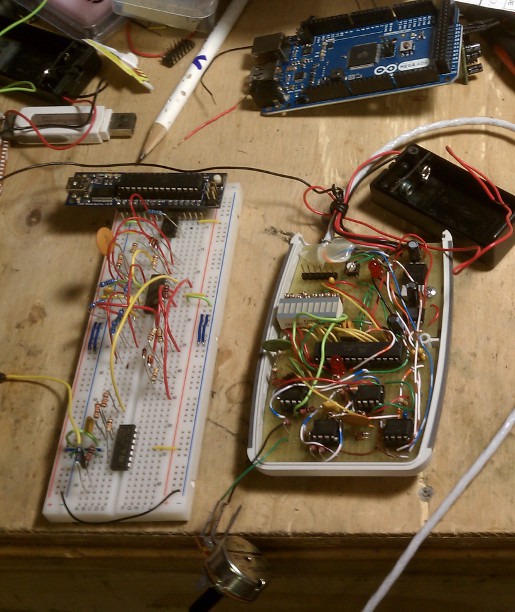
Now, initially, I was going to build a completely custom system incorporating a microcontroller, and an artificial intelligence chip. I was very, VERY surprised to find out that the Arduino101 already incorporates a 128 node neural network into its design! And it already has an RTOS running on it. And even better yet, the board design is open sourced! With EagleCAD files! Holy crap! This saves me a ton of work. So, the next step is to get rid of the blinking LED's, and to incorporate the Arduino101 design with the analog designs into a custom board to start prototyping the Mark 2 of the sensor suite.
-
Moving the Synthetic Spine Muscle Suit Forward
04/18/2016 at 19:55 • 2 commentsI haven't been on site as often as I've been intensively getting a startup up and running, which happens to be a combination app/hardware startup. That said, I'm still messing around with the biosuit sensor device. Several things I want to add this time around is an angle sensor to create a correlation between limb angle and the SEMG signal, and I've moved on to pure atmel controller programming. I've had enough with the Arduino, and it's been high time to take the training wheels off. Which is good, because I can move right into ARM controller programming for my stuff.
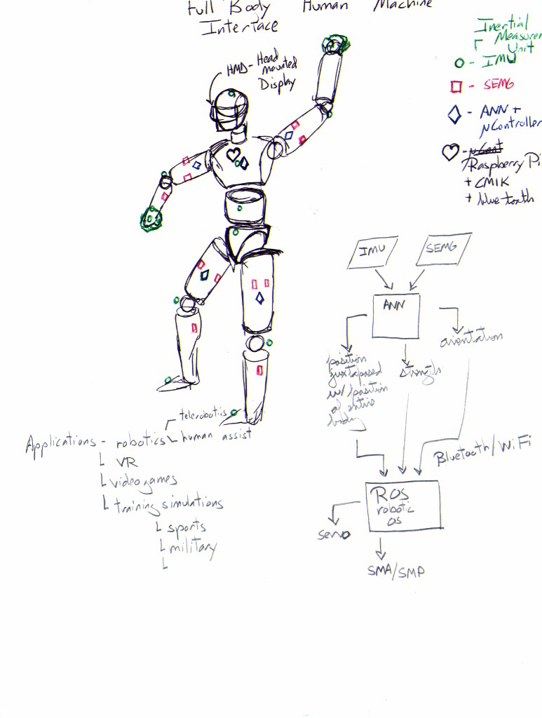
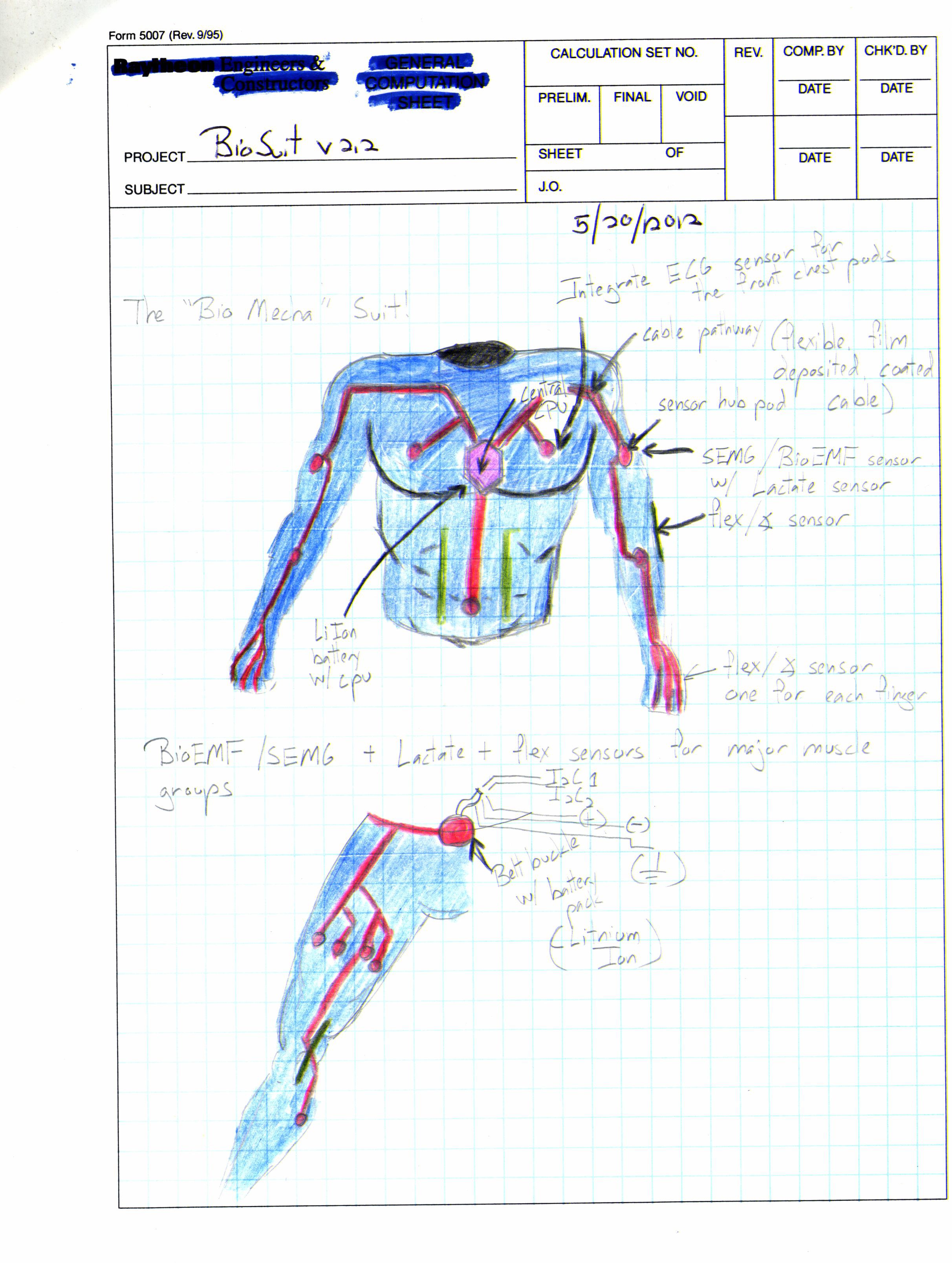
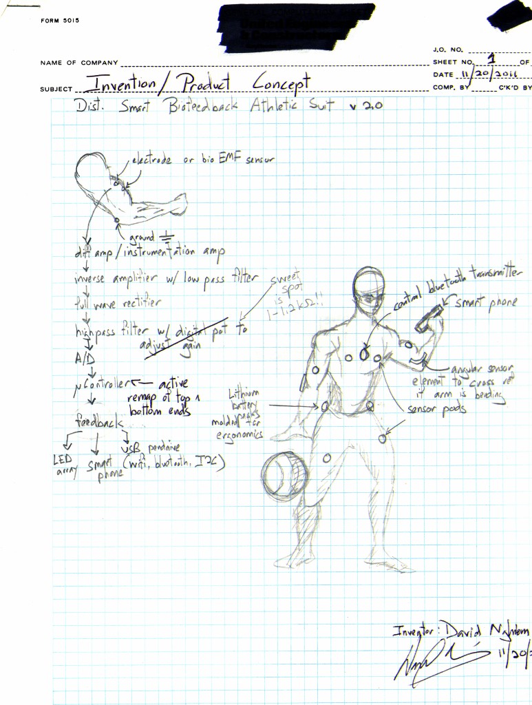
I am continuing my original vision for the suit as per my Grand Vision.
![]()
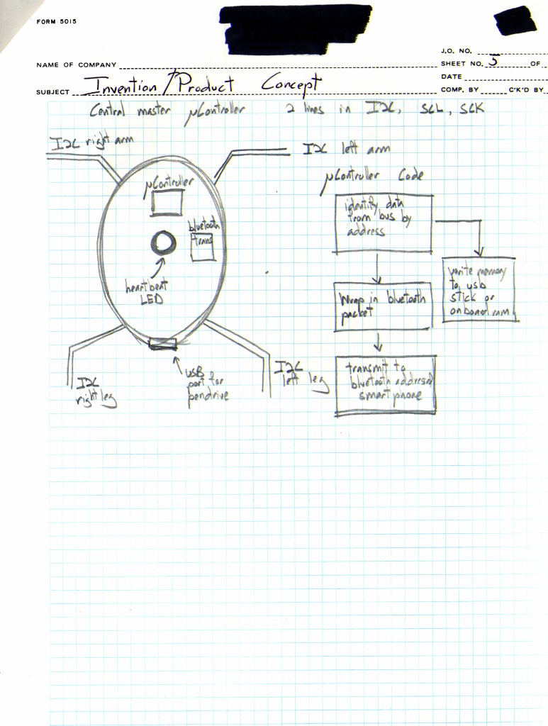
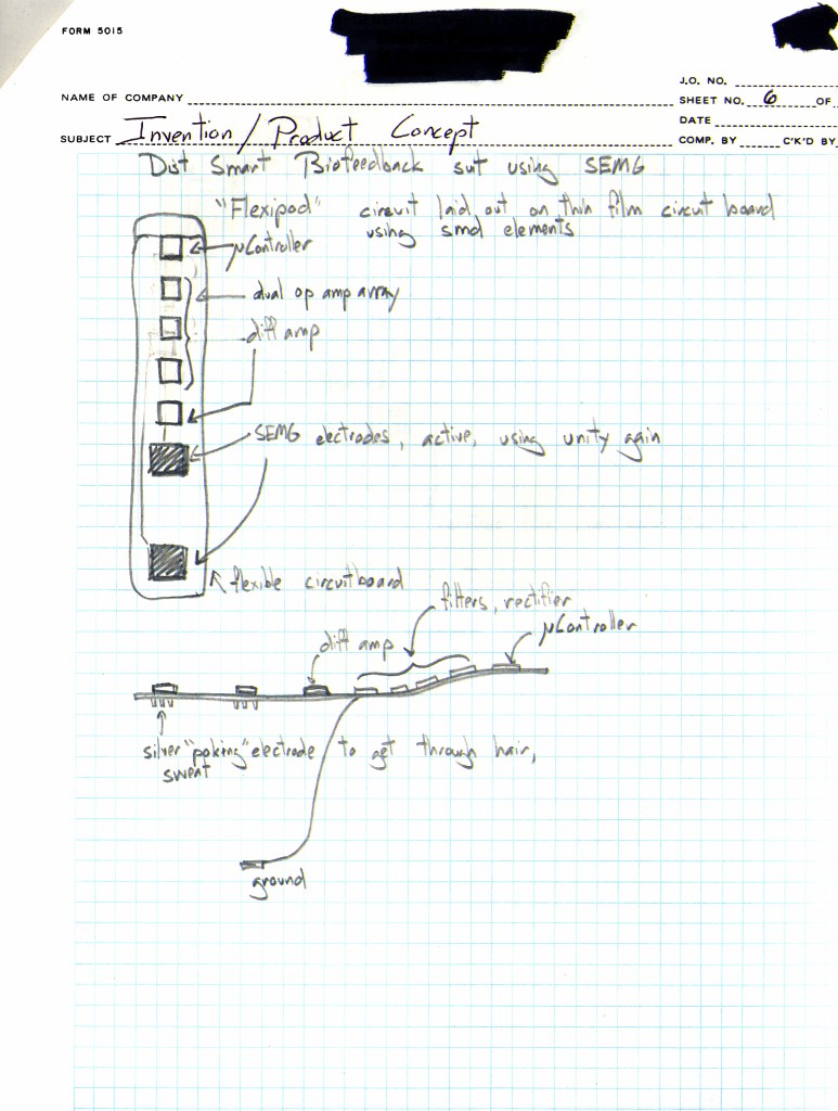
This time around, I'm going to be building this set of augmented reality goggles, and integrating it with the suit. For the suit, I'm adding in a bunch of different sensors in addition to SEMG. Like angle sensing and an IMU.
http://www.thingiverse.com/thing:721498
The original concept was to create a more suitable human/machine interface. I've never been a fan of smartphones, or interacting with a computer with very nonintuitive external devices. Not to mention, I'm karate/dancer/kinetic motion person, so for me, human body movement should be the natural way to interact with technology. Building a full on smart sensing suit comes a lot closer to that ideal.
-
Algorithms, Code, and Cases
04/20/2015 at 21:15 • 0 commentsThis week we address algorithms, code, and appearance. Or cases.
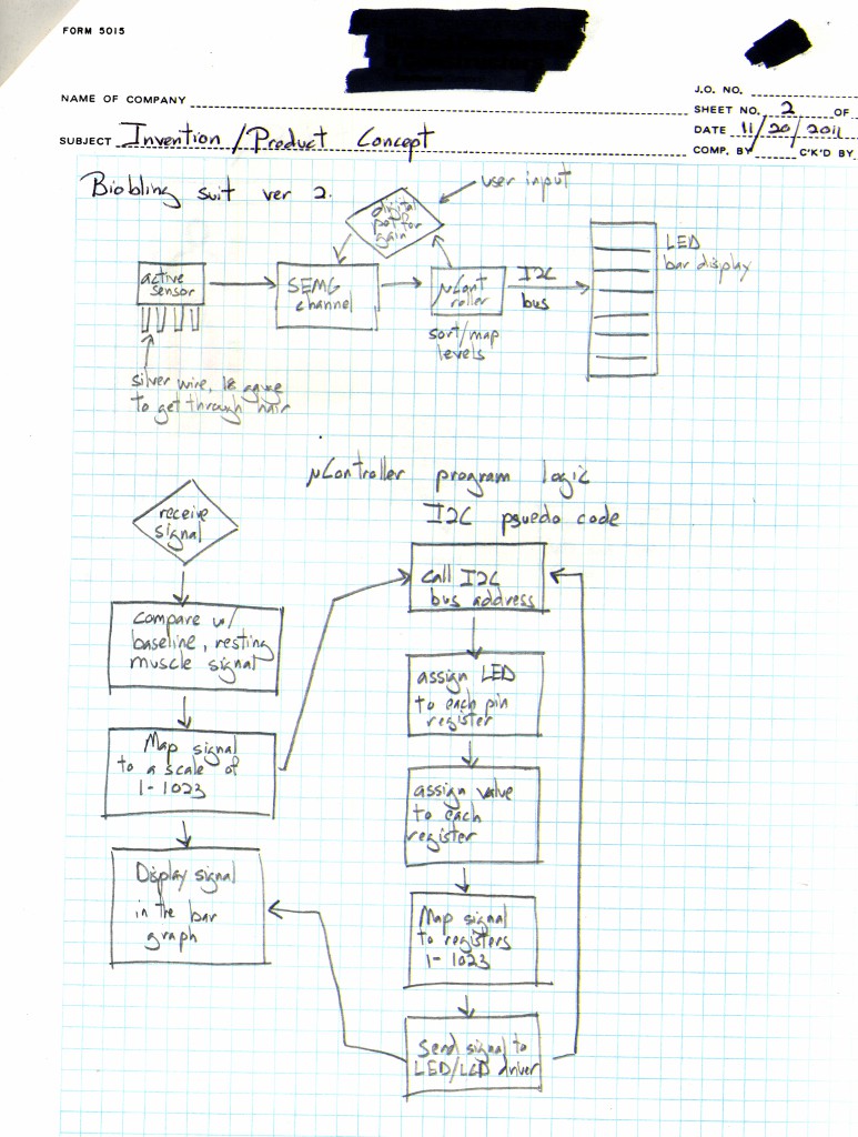
Let's start with code. For a device like this, where we're not interested in doing any kind of medical work - plus we don't want nor need to deal with the FDA - and it's just involved in controlling digital outputs for lights, artificial muscles, servos, etc, you don't need a lot of accuracy. The Arduino's 10 bit ADC is sufficient for most project needs when it comes to that. That greatly simplifies our processing. The basic functional requirement is to read in the SEMG signal, map the signal out to the PWM ports of the TLC5940NT in ascending order, and allow for software interrupts using soft IRQ's for button push instances so that when the button is pushed, the MCP42XX digital pot either lowers the resistance or increases the resistance to increase or decrease the gain so we don't oversaturate the final output signal.
The Atmega328P we're using is the low powered one, which works at 3.3V. Obviously if our signal overshoots 3.3V, we won't get a useful reading, so having the gain adjustable on the fly is necessary.
Right now, as it is, the program is a hack, due to the preliminary board being manufactured proof of concept. So, a lot of the dedicated serial channels that the Arduino uses isn't standardized across the board. Instead of the I2C port, which is the Analog 4 and 5 ports, we have it occupied by the switches for the MCP42XX, which is the SPI digital Pot. For the SPI, which typically is PWM 11, 12, and 13, we have that taken up by the TLC5940NT.
That's a real mess.
Anyway, here is the flowchart program for the circuitry.![]()
And here's the code. Starting with the main function in the Arduino.
#include <PinChangeInt.h>
#include <DigiPot.h>
#include <Tlc5940.h>

#define Int_Pin1 A1  // assign Analog1 to be the Interrupt Pin 1, Up Pin
#define Int_Pin2 A2  // assign Analog2 to be the Interrupt Pin 2, Down Pin

#define analogPin A0  // select Pin 0 for analog input

volatile int state = LOW;
volatile int state2 = LOW;

int StateUp;  // the button up state
int StateDn;  // the button down state
int PressUpNum;  // the number of button presses for the up button
int PressDnNum;  // the number of button presses for the down button

int valueUp;  // The previous value of the Up button
int valueDn;  // The previous value of the Down button

int slider = 5;  //setup variables for the digital pot 0
int val;

DigiPot mcp4251(5, 6, 7);  // Start instance mcp4251
/* Format: DigiPot <instance>(CS, SCK, SDI) */

uint8_t latest_interrupted_pin;
uint8_t interrupt_count[2]={0};  // Setup two interrupt pins

void setup() {
  StateUp = digitalRead(Int_Pin1);  // Read in the initial state
  StateDn = digitalRead(Int_Pin2);  // of the Interrupt Pins

  PCintPort::attachInterrupt(Int_Pin1, digipot_slider, CHANGE);  // Call the Interrupt
  PCintPort::attachInterrupt(Int_Pin2, digipot_slider, CHANGE);  // Call the Interrupt

  mcp4251.clear(0);  // Clear the pot 0
  mcp4251.clear(1);  // Clear the pot 1

  Tlc.init();
  Tlc.clear();
  //Serial.begin(9600);

}
void loop() {

  muscle_semg_read();
  //Serial.println(slider);
}
void digipot_slider() { valueUp = digitalRead(Int_Pin1); // read in the current state // of the button up pin valueDn = digitalRead(Int_Pin2); // read in the current state /* Start of the Decision Tree for Up and Down Buttons */ if (valueUp != StateUp) { // if the value changed if (valueUp == HIGH) { // and if the button is on if (0 < slider < 10) { // PressUpNum++; // Add one to the number of presses slider++; // Serial.println(PressUpNum); // Serial.println(slider); } } } StateUp = valueUp; // make the buttState current if (valueDn != StateDn) { // if the value changed if (valueDn == HIGH) { // and the button returned (pull up) if (0 < slider < 10) { // PressDnNum++; slider--; // Serial.println(PressDnNum); // Serial.println(slider); } } } StateDn = valueDn; // make the buttState current if (slider < 0) { slider = 0; } else if (slider > 9) { slider = 9; } val = map(slider, 0, 9, 0, 255); mcp4251.write(0, val); }void muscle_semg_read() { int sensorReading = analogRead(analogPin); // read in the Analog pin data //Tlc.clear(); for (int channels = 0; channels < 11; channels += 1) { } // run through channels 0-9 for a total of 10 channels and clear them int channels = map(sensorReading, 0, 1024, 0, 11); // loop over the LED array for (int TlcLED = 0; TlcLED < 11; TlcLED++) { // turn the channel on if (TlcLED < channels) { Tlc.set(TlcLED, 3000); // set the luminosity at max value //Tlc.update(); //send the data to the TLC5940NT } // turn off all pins higher than the channels level else { Tlc.set(TlcLED, 0); //Tlc.update(); // sedn the data to the TLC5940NT } Tlc.update(); //delay(50); } //Tlc.update(); //Serial.println(sensorReading); }
CasesHere's the thing about mixing circuitry with clothing. Or at least, circuit boards, with clothing.
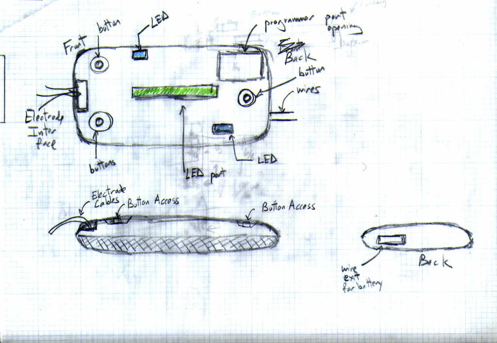
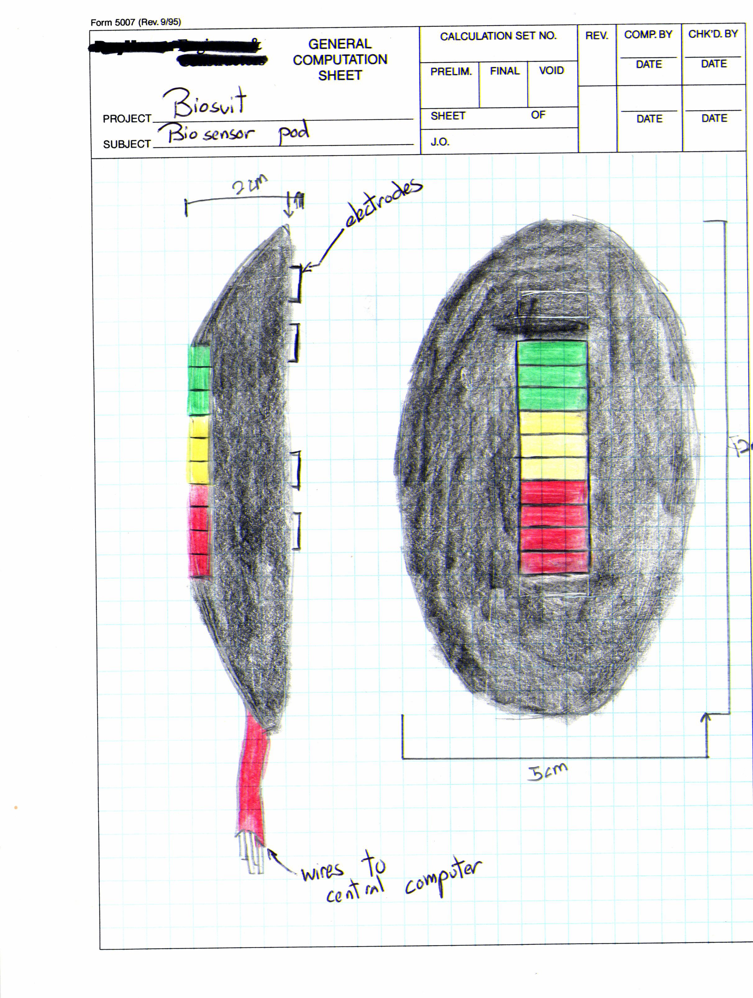
It's uncomfortable. I've gone running with all kinds of crap strapped to my body. And that $#it is just plain uncomfortable! About the only thing I can really stand using is a watch. So, while the form factor of the board is far nicer, it's still a circuit board. Which meant that I had to come up with a piece of packaging to make this somewhat presentable. What I came up with was this.
![]()
![]()
![]()
The "pod" is designed to be small, and easy to velcro on to any garment. The back of it is hot glued to a velcro strip (the hook part), while the garment has the velcro furry part. It leaves button access to adjust the gain, and access ports for the programmer to access, and for the electrode wires.
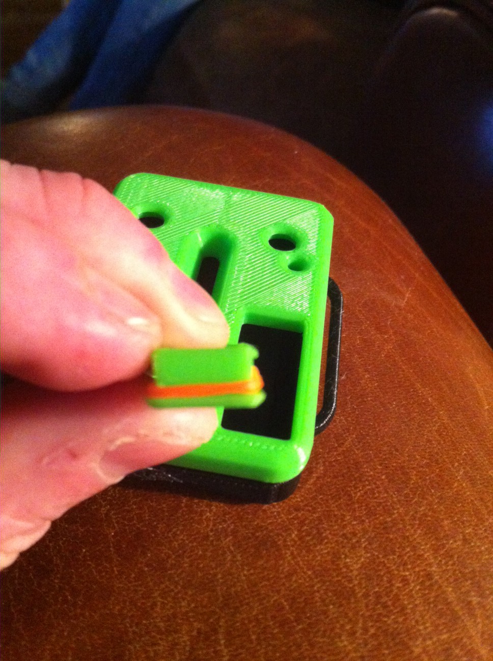
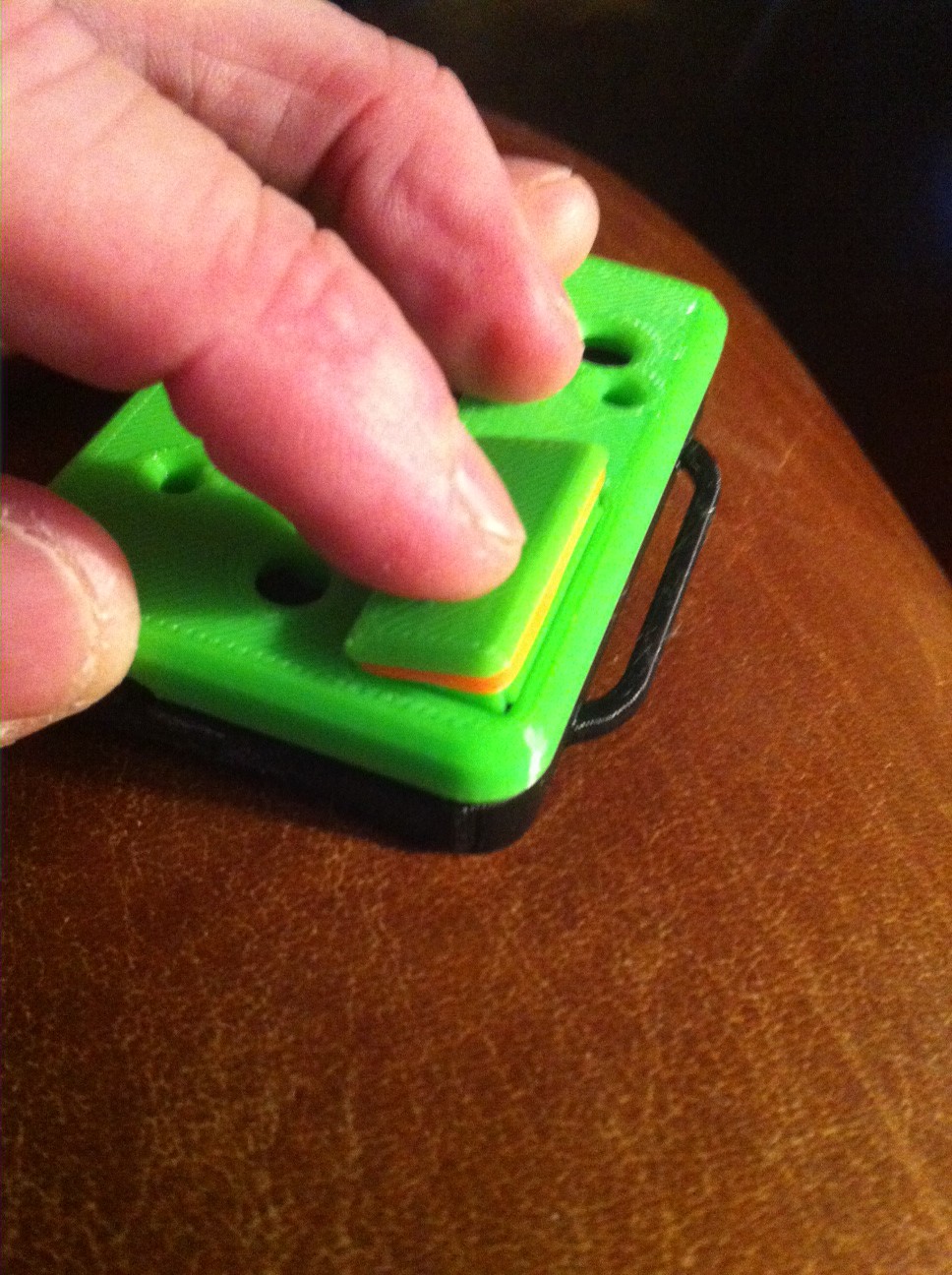
A friend of mine had it 3D printed. And this was the result.![]()
![]()
We soldered on the wires and attached a set of disposable electrode pads, and I hot glued a velcro backer to the pod so I can attach it to any of my bicycle clothes. Because when you're creating a wearable, obviously it's gotta go on someone wearing tight pants/shirts. Yeah...
Anyway, here's the end result.Coming up next, The School of Hardware Startup Hard Knocks Lesson 2, and the Amazingly reconfigurable SEMG sensor pod!
-
Honey, I shrunk the SEMG Pod, and Artificial Muscle Madness
04/08/2015 at 16:31 • 0 commentsAh, weight. It's the perennial First World problem, in an overly politically correct society. And it's the part of the circuit that we want to vastly reduce and size down.
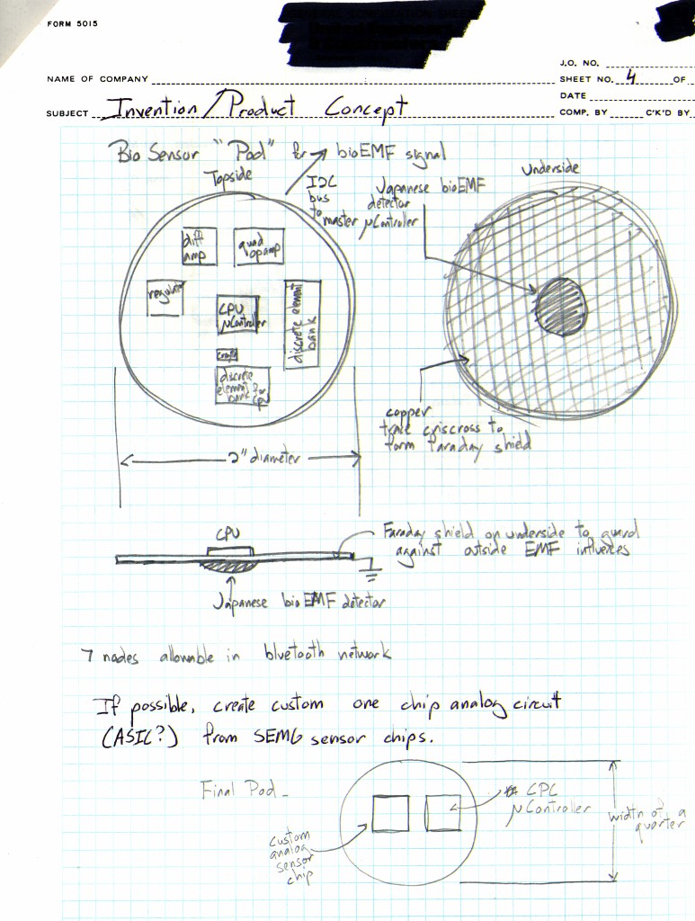
After we refined the circuitry, it was time to lay out the board and manufacture the PCB. We got to this point because as I attempted to make another basement, wire jumpered, ghetto board, my left over solder slag caused shorts and fried chips. I talked to Al, and he said to not even bother, since the proof of concept was solid, and I extensively tested my other hand made board. It was time to make something cleaner, smaller, and better.
I'm a total dunce when it comes to PCB board design and software, like Altium Designer or EagleCAD, which is what Aleks had access to. However, for circuit schematics, I used gEDA, which is an excellent piece of software for anyone who isn't rolling in cash to do their circuit schematic.
Artificial Muscle ControlIt's about this time that I really started thinking through the applications for my concept, and the first concept that came to my mind, was in robotics. Which brings me back to my ancient 1990's thesis, A Smart Suit for Microgravity Environments
Digital control of artificial muscles is a tricky problem. The problem with the current solutions out on the market today for artificial muscles, at least the kinds that make me think of an artificial muscle, is that they're not really digitally controllable. That's Shape Memory Alloys, IE. Nitinol wire, or shape memory polymers. Every Shape Memory substance requires heat or heat production for it to do the bending and contorting that makes it a muscle. And the problem with heat is the lag time for the material to absorb enough heat to result in a hysteresis, where the crystal structure, or whatever structure starts to rearrange itself into a different geometric form, resulting in a contracting element.
And because the hysteresis is heat dependent, and depends on the overall amorphous shape of the SMA/SMP, you don't get good control over the element. Now contrast that with biological muscles.
The Digital Nature of Biological Muscles
![]()
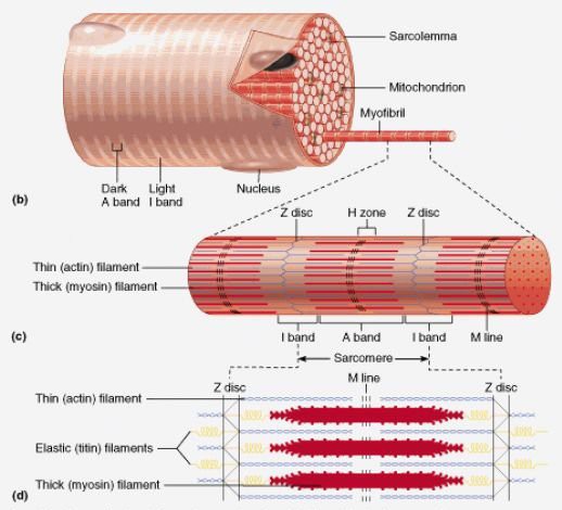
Biological muscles are formed of muscle fibers that ratchet against each other, with a myosin and actin element. Think car jack hoists. Much like a ratchet, they work in discrete steps with each other. You know what the crazy thing is about biological muscles? They're far better structurally for something resembling digital control.
![]()
That's because muscle fibers have a discrete nature. They use calcium ions, which have a defined energetic value, to initiate the muscle innervation. Basically, the entire muscle fiber is in a potential state, except it's covered with a sheet of tropomyosin. Each calcium ion tugs a bit of that sheet away, exposing binding sites on myosin. The actin filament instantly latches onto those myosin sites, creating a muscle ratcheting effect, aka the contraction.
![]()
You can read more about how the muscle works here.
Each calcium ion, and each actin/myosin unit makes a defined, structural, energetically activated biomechanical unit. Say that 6 times fast. Anyway, that makes it a clear analog to digital.
On top of that, not all of your muscle fibers activate at once when you innervate them. The only time you really see your muscles innervate almost at once is when you induce a massive shock to the muscle. That's why you hear stories of people who accidentally touched a massive circuit, get knocked out and find themselves 15 feet away. It wasn't a massive spark or explosion that knocked them back there. It was the shock that triggered their muscles to contract violently all at once. Now, if the contraction caused them to rigidly hold the electrical source, most likely they'd be dead. If the contraction caused them to leap back and let go of the source, more likely they'll still be alive. And when they woke up, that is, if they weren't dead, they felt really really sore. I know I did when I got hit!
Working with Artificial Muscles
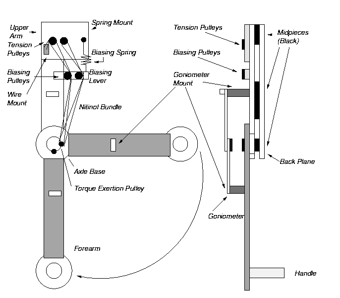
Now, when I did my thesis, this was the rigid structure I built to apply my artificial muscles on. The artificial muscle in question, is an artificial bicep.![]()
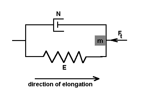
You'll notice that my arm's muscle is built according to the Hill Muscle model.
![]()
The nitinol, due to its super-elasticity, formed the contracting and spring elements. But it still needed a compressible element., which is the role of the biasing spring and lever.
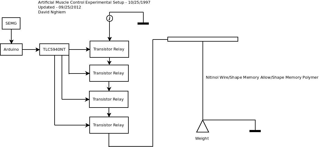
Today, this would be my artificial muscle control setup, using any kind of SMA/SMP and my SEMG pod as the controller.
![]()
The TLC5940NT, which I'm using to drive the LED's, allows for a step like output that I can use as a pseudo digital control, with say, an array of transistors to relays for amps.So, yes, I'm on a hunt for a better artificial muscle to control. And don't talk to me about servos. I also don't like, in fact, I completely DETEST using servos on the human body. They're clunky, inefficient, and inelegant. Unless you can make a compelling case.
So, theoretically, while the sensor pod can be used for digital control, as shown here, for the lack of a digitally controlled artificial muscle, it won't work as well. Still, this is the end result of what I want to see with my work. And a lot of times, the technology isn't always up to par with the vision, though I hope to have that changed soon. Side note, in case you're wondering, yes, I did all of these sketches. I used to draw comic books growing up, and I still do sci fi/comic book/manga art for fun.
![]()
Back to shrinking the SEMG Pod
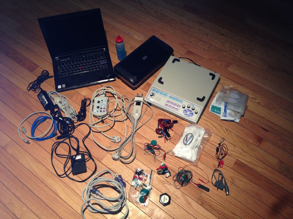
Back in late 2012, Aleks and I cleaned up and condensed the circuit. We wanted to take the functionality of your typical SEMG data collection device, like this clunky and awkward piece of lab equipment .
![]()
And shrink it into something that would fit this concept.
![]()
![]()
And this is what came out.
![]()
You can see the circuit design progression here.![]()
Gorgeous, isn't it? Aleks is a true artist. But hardware and circuits is only a small part of the picture.
Code is where the magic sauce is, and code is what I brew. What's funny about this is if you stick me in front of a computer and tell me to code for the computer or the web or some dumbass app, my eyes will glaze over. But stick me in front of a coke machine, and I am all over that $#!t. Coming up next week, I'll show you some of the basic code for the device, and I'll tell you about the School of Hardware Startup Hard Knocks Lesson 2!
Cuz nothing teaches you better than Real Life kicking the crap out of you! -
A Lesson in SEMG and Analog Physiological Sensing Electronics.
04/02/2015 at 16:02 • 1 commentSo now we get into the meat of the tech. The good stuff. The Biomedical Engineering coke. It's where the silicon meets the carbon road, where synthetic "life" meets organic "life."
The blending of biology and physics was what got me into biomedical engineering in the first place. Meshing organic with inorganic has this perverse pull for me. Yes, I was the one who found the Borg queen in Star Trek Voyager, the Matrix human batteries, and anime cyborgs sexy as hell, especially with all the attachments put on em. Do I have a sick fetish? Maybe. Is it Visionary? Absolutely.![]()
I started down this path when I was 5 years old, and licked a nine volt battery. That buzz was what got me going. When I was ten, I dissected disposable cameras, and gave myself severe shocks from the flash capacitor as an experiment, and for fun. I also got hit by lightning when I was in college, but that's a story for another day. Since day one, I've had this strange predeliction for electricity and the body, and attaching hardware to my body, for good or bad, is very natural for me.
Naturally I gravitated to muscles and electronics. So what better thing to work with than SEMG? Let's sing the Body Electric.
And now for a lesson in Surface Electromyography, or SEMG for short.![]()
An SEMG signal is an electrical wave that cascades down your muscle. That wave is generated when something called a Motor Unit Action Potential, MUAP, which is a combination of muscle neurons (Motor Neuron) and muscle fibers, starts with a discharge of a set of neuron potentials.
Those potentials are formed from the separation of sodium and potassium - which are positive ions - and chloride ions - which are negative ions - inside of the neural cell synapse, which is that long, tenuous line in the neural cell circuit. At the end point of the neural cell, where the neural electrical discharge ends, it releases neurotransmitters into the muscle cells, which in turn releases cascades of calcium ions, and that triggers the muscle fibers to contract. Now you know why salt, bananas, milk and leafy greens are important for your diet.
That discharge wave cascades down your muscle, creating what's called a Motor Unit Action Potential Train, which is a long line of MUAP's discharging to the end of the muscle. That end, is where the muscle is attached to ligaments or tendons, which in turn are attached to skeletal bone. And that's why you need a ground near bone to complete the circuit.
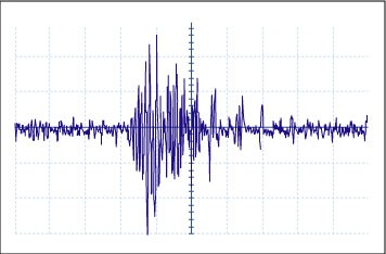
The full electrical discharge is both motor neural cells discharging, and muscle potentials discharging, ending with one giant, cascade of voltages coming out from your muscles. Which gets really messy, and complicated looking. Like this.![]()
What the electrode is measuring is the muscle discharge from the calcium ions. Lost somewhere in that signal are the motor neuron cells, but those aren't that important to look at for our purposes.To read electrical signals from muscles, we start with a differential amplifier, aka a diff amp. You need the diff amp because it subtracts the voltage values measured between the two electrodes.
All the diff amp does is it measures a point in the wave, versus another point in the wave, while the ground provides a base reference. When it subtracts those values, you have a voltage value from the muscle, and that's the signal you're working with.
Now, some SEMG circuits use a single electrode, and a ground. Others, like the one we're using, use the belly of the muscle, the ending of the muscle (right where it attaches to tendons), and the ground. You can also get crazier with triple, quad electrodes to get as much signal value as possible.
This improves the resolution of the signal, because of the number of contact points on the skin. But it also gets a lot more uncomfortable. There's a lot of metal shafing on your skin all in a concentrated point.
Good instrumentation diff amps meet these minimum parameters.- Low internal noise (<0.5 mV)
- High input impedance (>100 MΩ)
- Flat bandwidth and sharp high and low frequency cutoffs (>18dB/octave).
- High common mode rejection ratio (CMRR > 107 dB)
- Common mode input range (CMR > ±200 mV)
- Static electricity shock protection (>2000 V)
- Gain stability > ±1%
All of these are important, especially common mode rejection ratio, but the one I consider most important, is high input impedance. You need a high input impedance because you want minimal loading to avoid distorting the signal. Remember, the human body is an AC machine... except for a segment of your brain, which produces more DC.One of the problems - among many - with SEMG is sweat. Sweat is filled with salts (Sodium ions, +, and Chloride ions, - ), and salt is what makes water conductive. Now, if you have an electrode (the skin contact) with high impedance, and an amplifier with low impedance, you could get a voltage divider formed between your sweat and the electrodes. Which means loss of signal.
I want this to work with any kind of skin in any condition. Not a lab environment where you get to clean the skin with alcohol swabs and scrape it to create better contact. I work under presumptions that the ex Soviet Union worked under, that the conditions are going to be dirty, nasty, and very unideal.
Designing a Better Sensor Platform
When I started this whole endeavour, I started with the Advancer Technologies circuit.![]()
I had a lot of problems with it: oversaturation, expense, 60Hz signal, bipolar voltage from two 9 volt batteries, tiny pots that died quickly, loose and faulty connection to the Arduino, and more. Which is why we threw out the whole design, and designed a new one.![]()
The Advancer circuit used an INA106 differential amplifier for the interface with the electrodes. The INA106 is a pricey piece of silicon, and it costs 12 bucks. The INA106 has a few technical issues as well. First you have to use a resistor to set the gain, and a lot of times, you can set the gain too high, you can't adjust it because it's a static resistor, and replacing it with a pot at the very beginning of the circuit means you'll severely oversaturate the rest of the circuit which is decked with filters that have their own gain adjusters. And that's exactly what happened to me. I spent weeks trying to come up with ways to fine tune multiple gain adjustments, when I should've just thrown out the INA106 in the first place.
The other problem with the INA106 was cost. Now, when you're operating on as much of a shoe string as I am, you quickly learn how to get good results fast, on very little. So we got rid of the INA106. I got the INA106 through Texas Instrument's free sample program, which is OK when you're experimenting with a pod or two, but I needed to build a lot more than that for the entire body, which adds up the cost. Even at volume, the price drop isn't that much, especially for the performance I was getting from it.
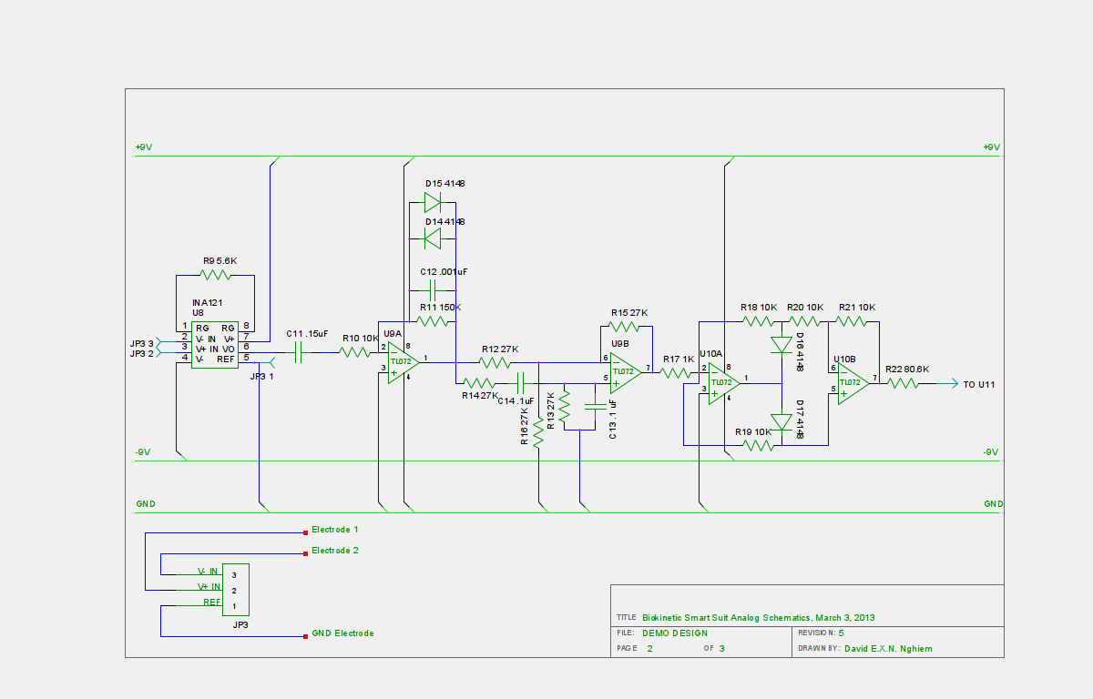
So, Al and I substituted the INA121, which is more capable, with the benefit of being low power. The INA121 is also half the price of the INA106, it didn't come with that gain setter, which meant I can concentrate on the digital pot at the end filter. I got better control with that setup.![]()
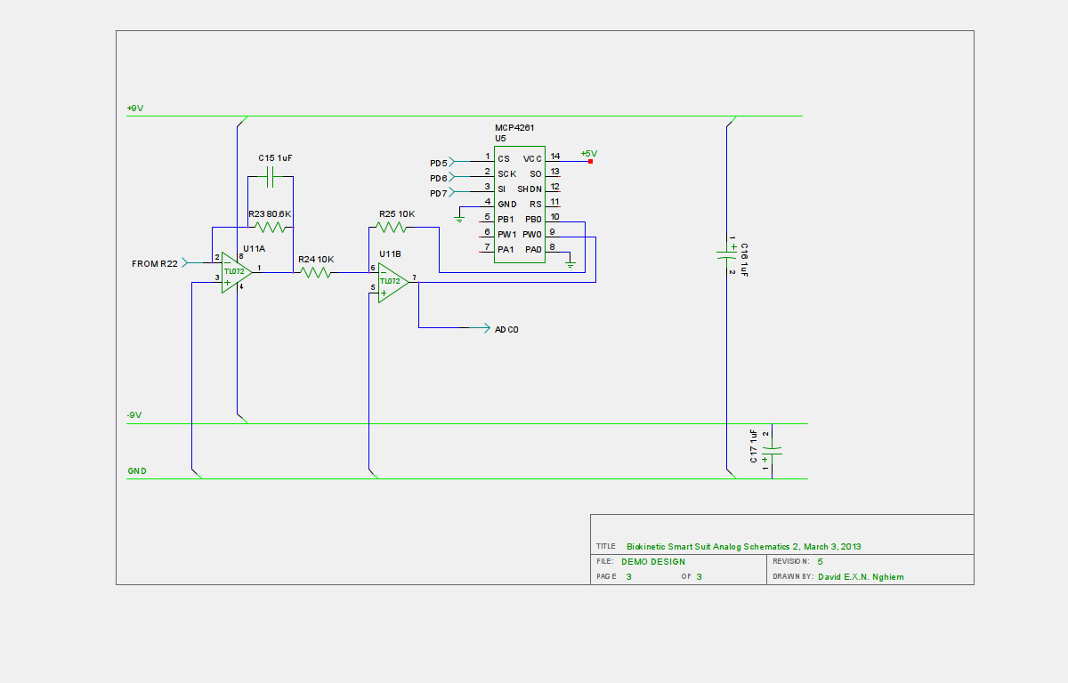
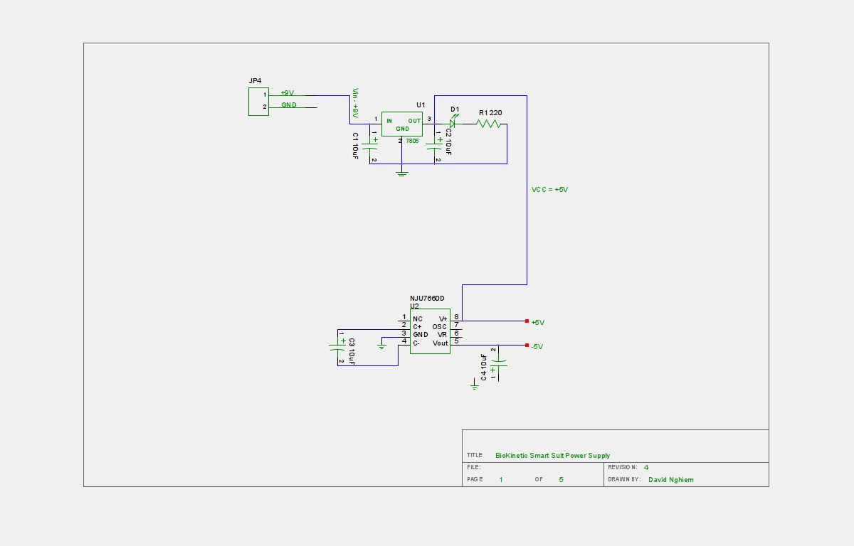
Next was the succession of filters. Al suggested we put in a notch filter to get rid of the 60Hz signal. The Advancer circuit relied on the Diff Amp to remove that signal, which is sufficient, but not always adequate. We also changed the configuration of the filters. We kept the wave rectifier, because when it comes to digital control, you don't need the negative portion of the signal. And we added the part I considered critical, the digital pot.I also didn't like using the two 9 volt batteries for + and - voltage supplies. That's just too heavy, klunky, and not wearable. So I used an inverting charge pump circuit to get rid of a battery, and generate a + voltage and a - voltage from one battery.
![]()
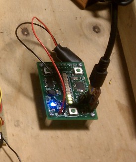
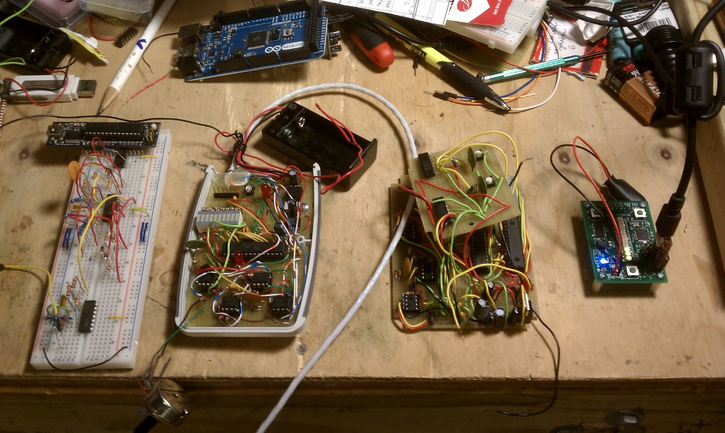
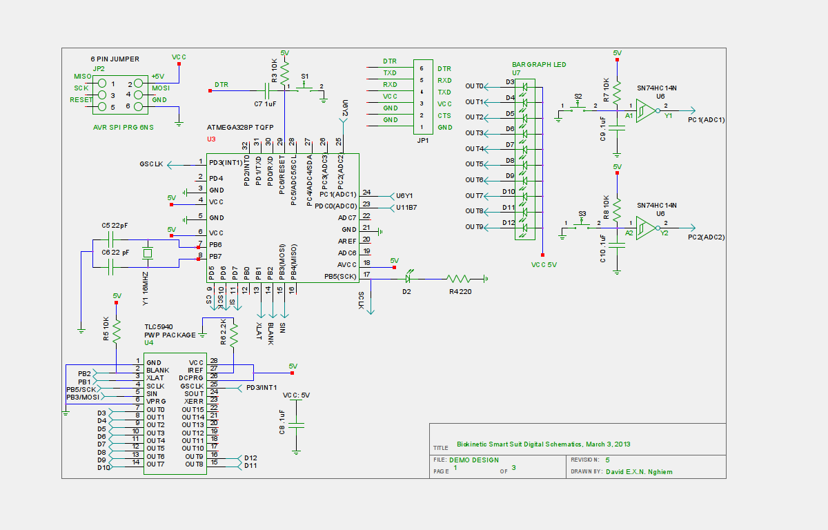
Next, I wanted full integration with the Atmel processor, and I wanted more PWM ports for more LED's. Which meant incorporating a TLC5940NT. I also wanted manual control of the digital pot through the Arduino IRQ's - which I used software for -, so two push button switches were put in. I also put the LED bar graph in there, and I wanted it to be easily programmable on the fly, so the 6 headers for a USB programmer is in there. This was "supposed" to be our demo circuit, designed to show off the concept to prospective investors.![]()
I did all of the digital circuitry and power supply. Al helped make a much better analog circuit, and we incorporated the digital pot with the analog circuitry. I had my refined circuit that I can digitally control with the Arduino, and that opened up a whole new realm of possibilities for Bluetooth, Wifi which leads to the Internet of Things, and Artificial Neural Network control.This was my new sensor platform. The other great thing about this design is its modularity. Prototyping this on the Arduino platform conferred a massive technological advantage due to the cross platform ability of the Wiring Open Source Framework.
Let's say I wanted more than what the Atmel328P could do as an 8bit microprocessor. If I wanted to, I can easily drop in the Freescale ARM in the Teensy (Wiring), or a Microchip MIPS based PIC32 Pinguino (Wiring) circuit for more power. I''ve also considered the Texas Instruments MSP430, because it's low power, and uses Energia (Wiring). Since I coded the software in the Arduino/Wiring framework, it's basically/kinda/sorta/maybe/wishful thinking cross compatible with those three other platforms.
That creates a massive time saver if I wanted to upgrade the microcontroller.The most important design goal of this platform was it formed neural unit for a suite of other sensors that I wanted to incorporate, like the IMU, an accelerometer, resistor sensors, etc. And going back to my original grand vision, with the Artificial Neural Network, it would form one node of a suit that had distributed, smart "nodes" sensing across the body - creating a wearable, external spinal network for the human body. As per the the Grand Vision.
![]()
But we still had some problems. For starters, the 9 volt battery is still a major problem. It's big, and not sufficiently wearable. Also, the components for the op amp filters weren't the best price/performance values out there. And we still needed to shrink the whole thing down to something we could manufacture.And this is where Al's expertise came to play.
Appendix: Software used to do the electronics layout is gEDA. -
The Wearable Synthetic Spine, and the School of Hardware Startup Hard Knocks - Lesson 1
03/31/2015 at 01:06 • 0 commentsLong before Marvel Comic's Iron Man movie series came out, and before Iron Man's technological concepts in the comic pages even got a veneer of plausibility, long before anime became mainstream, I watched a lot of Mecha Anime, from Robotech to Appleseed. I just enjoyed the art style and the stories. But the design concepts and ideas put forth by those "cartoons" were way, way ahead of their time. And one of the biggest influences in my work, is from Bubblegum Crisis.
![]()
Bubblegum Crisis was a futuristic, bladerunneresque, cyberpunk series long before the concept of cyberpunk gained traction. That show gave me the concept of the human body sensor suit back in the 1980's. The series never defined what exactly went into the suit, but I took that science fiction anime visionary concept, and ran like a bat out of hell with it.
Since I'm a visual person, I work a lot better with pictures. I'm also a sketch artist, so as usual, I went to my sketch book, coloring pencils and paints, and this is what I came up with.
The Full Body Human Machine Interface
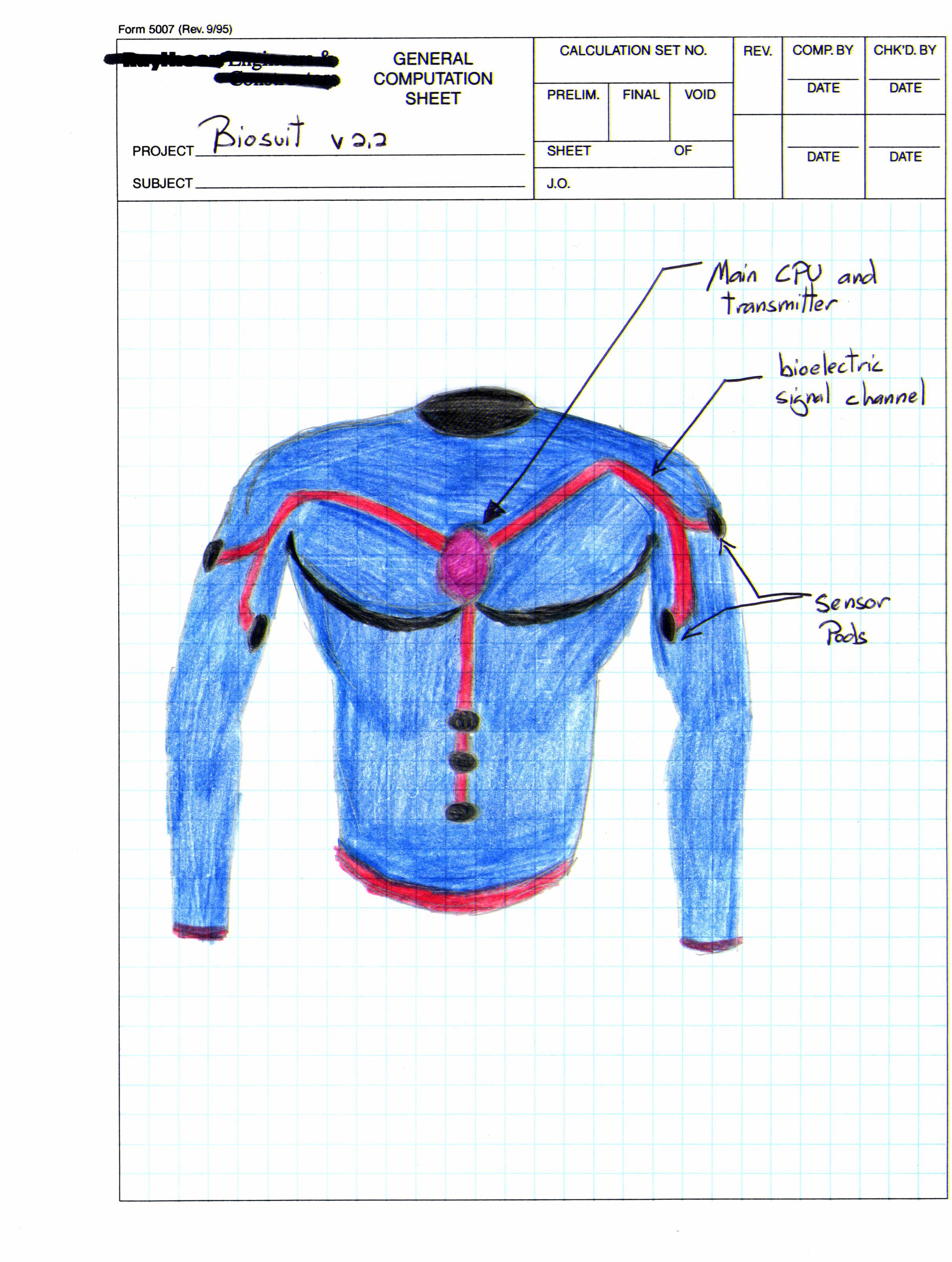
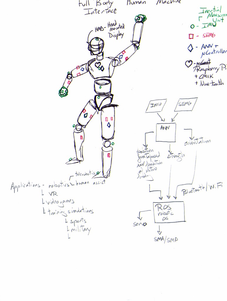
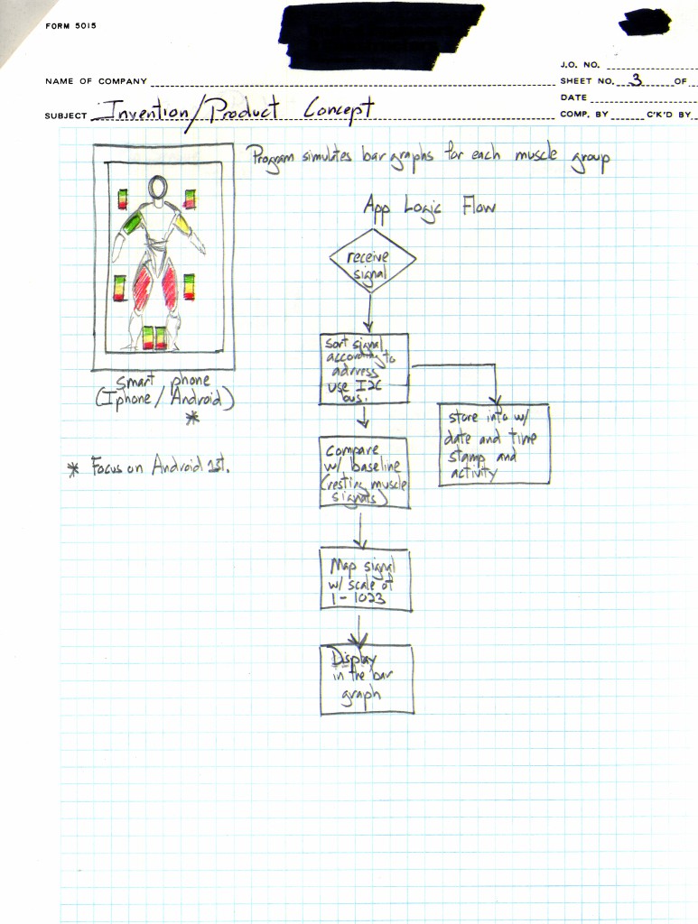
This is my grand vision for this concept. It's a unified, integrated, wearable body sensor suite that's unintrusive, and you can use it for controlling robots, VR, etc. It should record and replicate digitally the entire body's motions, forces, and physical parameters.![]()
The Artificial Neural Network is what makes the suit "smart." The problem with technologies like SEMG, or IMU's, or accelerometers is that just by themselves, they're not going to give you an overall picture of what the body is doing when it's in movement or applying a force.
Take SEMG for example. All SEMG does is measure the amount of innervation/contraction activity that your muscles are doing. Notice I didn't say movement. Ever done isometrics? Bruce Lee was a great proponent of isometrics.
![]()
Isometrics is where you hold the limb or muscle in place, and contract the hell out of the muscle, without actually moving. Bruce Lee's one of the biggest role models of my life. If you ever read his biography, he's probably one of the first documented proponents of a high tech approach to combat conditioning.
Anyway, you can fool an SEMG sensor into believing that you're contracting the muscle and interpret that as "movement." Hell, you can fool many sensors into believing that you're moving in certain ways. But once you've got a suite of sensors, with some learning ability embedded in them, you can get a far more accurate picture of what your body is doing.
Incorporating an Artificial Neural Network, and an array of sensors as a suit from the get go with a robotic operating system is a bit much to bite in the beginning. So, I scaled it down to something that I figured "should" be much more manageable for the near term.
![]()
![]()
![]()
![]()
![]()
![]()
![]()
![]()
The system as a whole is a networked, decentralized, sensory platform. It's a lot like your spinal neural system, which operates off of reflex. Everything you feel, physical perception, to limb and skeletal muscular movement, to reflex, even autonomous movement internally, emanates from your spinal cord.
The end result of all this technobabble, the great vision, is to build a wearable, synthetic spinal neural network that senses your body's motion, physical condition, and muscles, and make that information useful for digital control of devices.
Hardware Startup School of Hard Knocks - Lesson 1
The hard part in all of this wasn't the technical part. The hard part, is finding the right people and the right advice.At the time, (2011) I should've gone with my very first instinct, which was to immediately start laying out the design, and manufacturing the pod for sale to interested people. I told my partner at the time that what I wanted to do was to make the pod as is, and start selling it at conventions, meetups, shoot, I'd sell it on the street from a White Van if I had to. - Side note, I was one of those saps who actually bought a set of speakers from two dudes in a White Van. Supposedly, it was one of those 90's/early 2000's scams. Those speakers ended up being one of the best sets of speakers I had ...
Anyway, instead of following my business instincts, I took his advice that we should "keep developing the product", to make it "venture backable", and I ended up getting jerked around for almost 4 years, while struggling to live off of less than 8k a year, and funding this with my entire savings. Show some skin in the game? How about subcutaneous tissue, and blood vessels too?
But I'll get into those business/startup lessons in another post. After getting the pod working, it obviously wasn't wearable enough, because let's face it. This was my soldered by hand, jumper wired in the basement, slagged on a piece of prototyping board, ghetto prototype.
What I needed was electronics layout and PCB fabrication, but for SOIC or SMD sized electronics. That would shrink the board by several orders of magnitude. I also needed to tweak the analog circuitry to be more lower power, more sensitive, and without some of the impedance issues I was running into. I also needed it to be cheaper. At $12 per chip, the INA106 Differential amplifier is a pricey piece of silicon, and it's the most expensive chip on the board. Every single one I got was via Texas Instrument's free sample program.
And I can't keep scamming TI for free INA106 chips. And forget that at a production level! This is where manufacturability starts creeping in, and you have to account for that. Other wise, you'll have an innovative, and expensive, piece of work that no one will buy.So, while I'm a great rapid prototyper/designer/proof of concept technical artist, I sure as hell am not that great at the details and minutae of tricky analog electronics. And while I'm great at sketching out a circuit design, I'm not versed at all in PCB layout. Now that's an Art. For that, I went to an old friend of mine I graduated from BU with, who I consider one of the best analog electronics engineers on the East Coast, Al.
Al's the kind of person where you'll tell him what you want to pick up on when it comes to signals. You can tell it to him in a bar after a bunch of drinks. And right there, he'll whip out a napkin, and sketch out an op-amp/analog circuit design that will work the moment you implement it. He's that good. He's basically the Op-Amp whisperer, the Analog Ace. Naturally, Al puts those skills to good use and he works as an engineer at the Boston University Hearing Research Center. Al's also a veteran PCB board layout artist.I'll find help where I need it. You should never be afraid to toss your idea out to people who can give you a hand. Even tossing out to people period is important just to get an idea if it'll have a market and serve a purpose. A lot of folks get tripped up by their egos or their paranoia.
You shouldn't be afraid to "lose" ideas or that someone will "steal" it. Fact is, real implementers are far and few in between, and you have to test the idea out with regular folks. Ideas are a dime a dozen. And, no one is the "perfect" "all knowing" god of all things. That's just impossible. When it comes to starting up a company, or developing a product, you have to toss that ego aside for the sake of pragmatism. Need help? Find it.
So, what Al and I did next, was take my hand crafted kludge, and turn it into a finer kind of circuitry wine... -
Iterating the SEMG Sensor and Creating the Platform
03/19/2015 at 21:14 • 0 commentsSo, I had my requirements in my head for this next version. It had to be:
- Integrated into one unit
- Be easier to use
- Be wearable.
- The current set of op-amps needed better impedance values, in particular the differential amplifier which connected to the electrodes. Which meant a whole new set of op-amps
- Be easy to reprogram on the fly
I came up with this.
![]()
I also added a milspec shielded cable, since I noticed that the signal also got interference from, I'm not sure, static, EMF radiating from my body, whatever. The milspec cable had a nice shielding Faraday cage type around the wire strands, which I grounded.
Next, it was time to test it.
![]()
And you can see it in action here.
You can see how much cleaner the response is, versus my quick and dirty prototype. Oh man, it was a revelation! A few other innovations I incorporated are the electrode placement methods on the sleeve. I used velcro on the backs of the electrodes, and there's velcro inside the sleeve. This let's me adjust the position of the electrode on the fly. Now obviously, I wouldn't wear the pod like that, that's just asking for it if you fall on your chest. Also, it was a massive improvement over the Advancer circuit, which used this tiny analog pot to change gain values, and that pot usually died after 4 uses. So I replaced it with a BIG POT. Oh man, talk about way better.
Still, I ran into a bunch of problems with this one.
- The electrode contacts were uncomfortable. I was still using copper plates hot glued to velcro straps
- While this version was reprogrammable, and the chips were socketed so I could replace burnt chips, I had random shorts and connection issues because I was hand soldering wired jumper fashion to various pin outs. There was slag and left over solder EVERYWHERE. Talk about a headache debugging.
- I needed more LED lights to indicate my level. The Atmel Digital PWM's wasn't enough. That meant I needed an LED driver.
- The bigger pot was nice. But really inelegant. I wanted something I could digitally control.
- I was still oversaturating the op-amps. I needed a lower gain.
So, it was back to the drawing board with another design! But at the same time, it also meant I was getting close to a real product. And that meant generating a master plan...
-
Making it Wearable
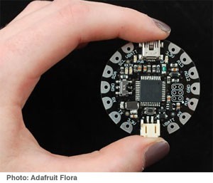
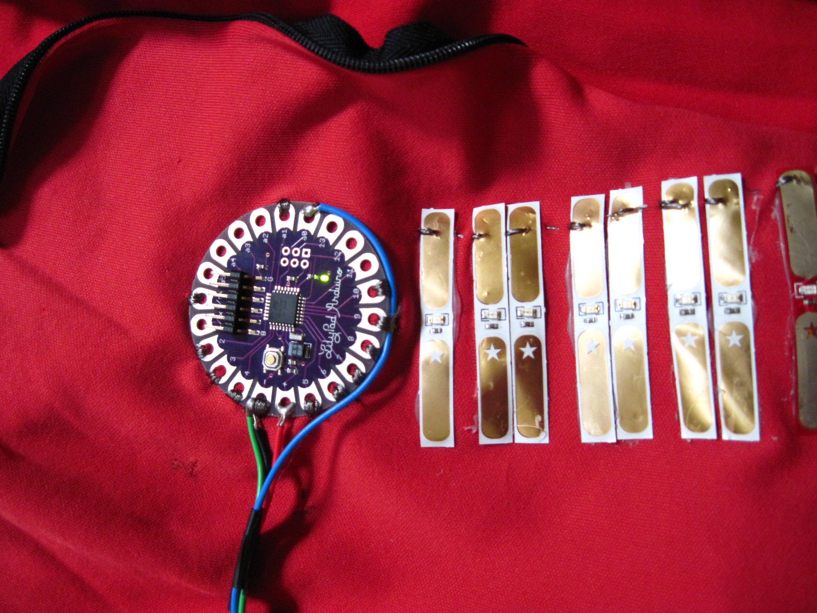
03/18/2015 at 23:55 • 0 commentsSo, now that the proof of concept worked, the next step was to make it wearable. After all, I wanted to run with this thing. So, I picked up some Adafruit Lilypads, (pre-flora)
Adafruit Flora![]()
And a whole bunch of sewable electronics, like sewable LED's and thread
Stainless Thin Conductive Thread
Adafruit LED Sequins - Warm White - Pack of 5
And routed the SEMG data through the Lilypad, like this.
I also wasn't fond of the signal strength I was getting through the Advancer board, so I built my own electrode with a basic opamp amplifier configuration directly at the skin contact surface. Which you can see here.
I then added the flora to my shirt, a bicycle jersey.
And here's what it looks like assembled.
And the whole thing.
I stopped at doing both sides because I had only one functioning set of electrodes (I fried two sets, and exchanged some emails with Advancer regarding what I was doing.)
And here's the first test of the idea.I used to be a kickboxing/martial arts instructor for a number of years, so yeah, Hell yeah, I'm going to do combat motions with this thing!
And here's a test of the concept with some weights.I then took it out for a walk with my dogs. In my opinion, if the technology you're using can't be put through its paces doing all kinds of weird crap, it's no more useful than a delicate toy.
I ran into a whole bunch of problems that I needed to work out though. For starters, I needed to integrate the unit into one small thing, as I wanted to get the SEMG signal from my other parts of my body as well. I also needed it to be smaller, and more flexible. My sweat also made the conductive thread wonky with the electrical signal, and overall, I wanted a better design. The Advancer Technologies circuit also oversaturated, and I had some issues with the circuitry itself. So, I threw out the entire design, and went back to the drawing board. I wanted to create a better circuit, a better electrode, a better way to change the gain, a better form factor, basically I wanted a much more useable wearable SEMG device. -
In the Beginning...
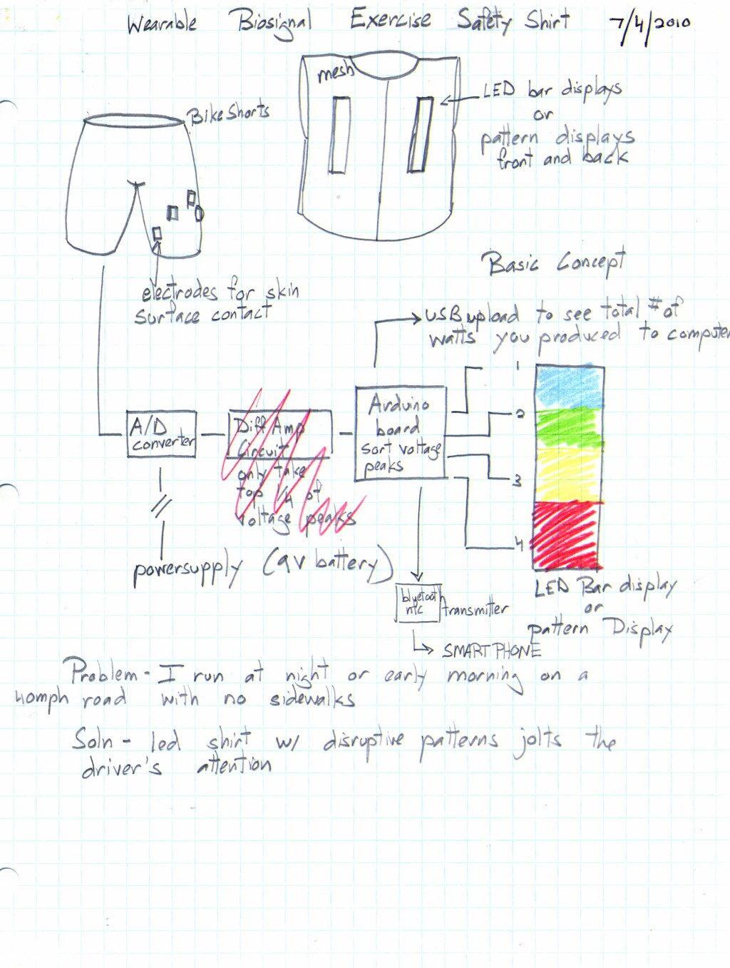
03/18/2015 at 21:18 • 0 commentsThe SEMG product concept started out in 2009 when I was running down a 3 mile route nearby my parent's home, and the road in particular is dark at night. There are few street lamps, and cars go down at a limit of 40mph, but let's be honest, most people don't give two $#!ts about speed limits. There's no sidewalk, and barely any shoulder. As I ran, I wondered if I could use the SEMG signal from my legs to control a light pattern to warn oncoming cars with a non patterned light show, like how some animals have vivid colors to ward off potential predators with a show of flair - that also meant they were poisonous.
![]()
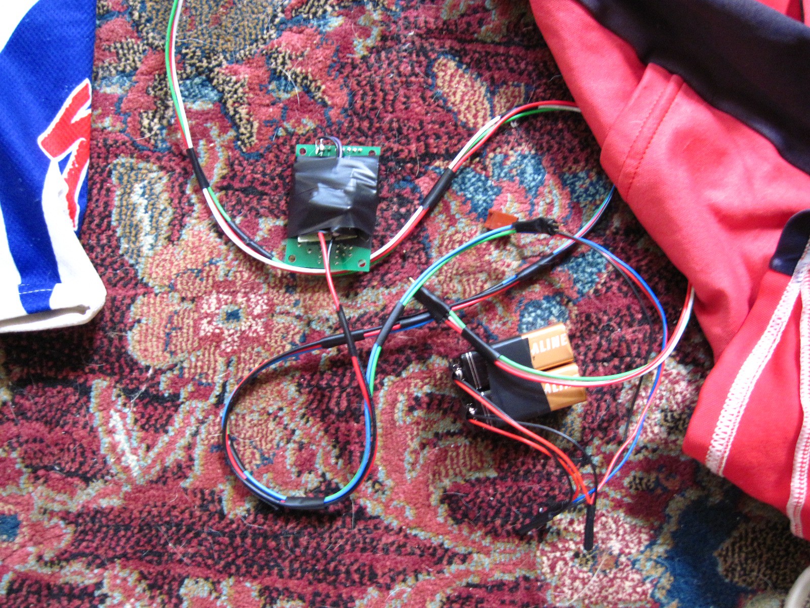
So, I went back to my ancient senior design thesis, which made use of SEMG signals to control robotics, and saw that the Arduino was coming along. And that's when it hit me. Combine the two. Here's the first quick and dirty prototype when I started testing the feasibility of the concept.
I'm a really fast prototyper. I like quick and dirty proof of concepts just to see if an idea is feasible, so naturally I grabbed one of my arduinos, and searched around for cheap electrodes. Advancer Technologies, http://www.advancertechnologies.com/
design came up, so scratch built one first, built a few using this Instructable, also from Advancer
Instructables SEMG sensor
, and after a few rounds with a klunky bread board, I then I bought some of their integrated circuit boards. I wanted to see if I could make a level meter of my muscles, using LED's. For that, here's the setup hooked up with some LED's.I then tested it out with some weights, to see how sensitive it was. So I curled a 25 pound weight to check it out.
The idea proved sound. It was onto the next step, to make it wearable.
SynthaSense Suit: Control Stuff With Your Muscles
A better human computer interface. A wearable sensor suit for controlling stuff using SEMG and body movement.
 Casual Cyborg