-
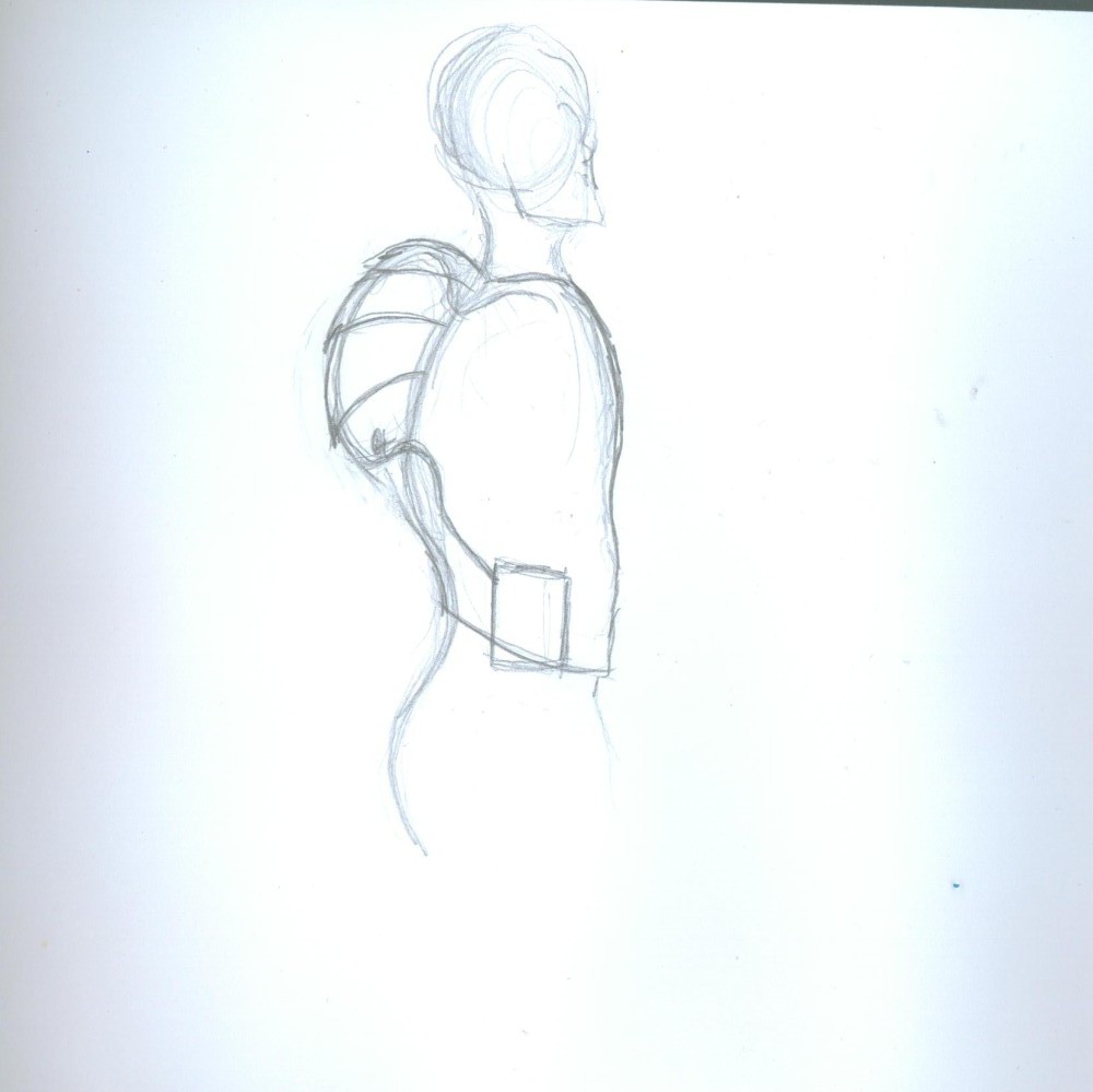
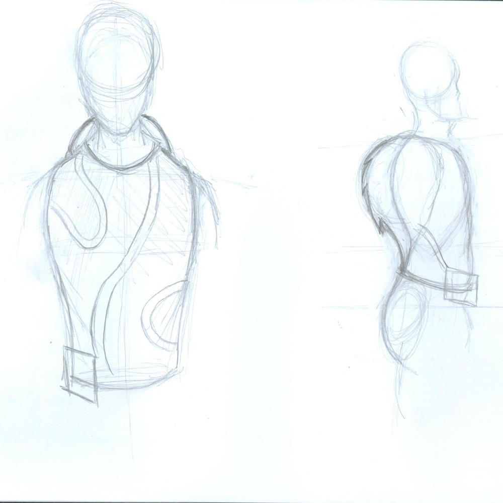
Artist’s Renditions
09/21/2015 at 19:22 • 0 comments![]()
Showing coolant tubing.
![]()
Cooling backpack optimal design look with servo valve hip belt.
![]()
Front and side views.
-
Testing the Mini Refrigeration System
09/21/2015 at 01:02 • 0 commentsHere is a video of my compressor testing. One thing that I am not sure about is how much R134A refrigerant I should charge the system with. I am also not completely sure what the high or low side pressures should be normally. I know that the high side pressure should not go above 350 psi. Overall the cool liquid does get rather cold. I need to get a better thermocouple because I believe mine is not very accurate.
-
Building the Mini Refrigeration System
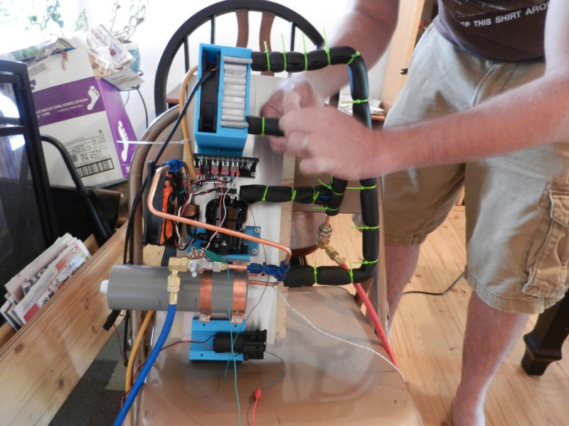
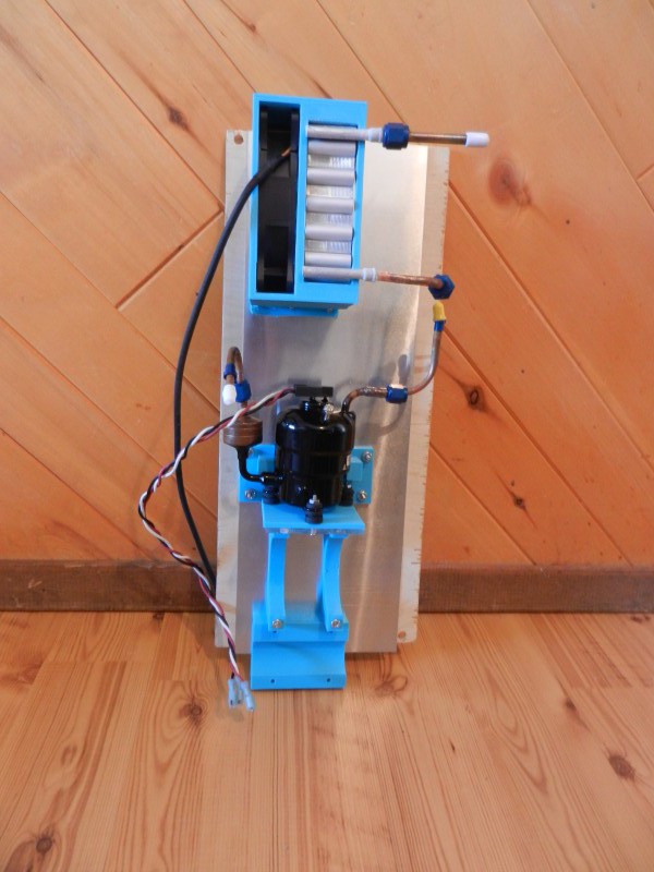
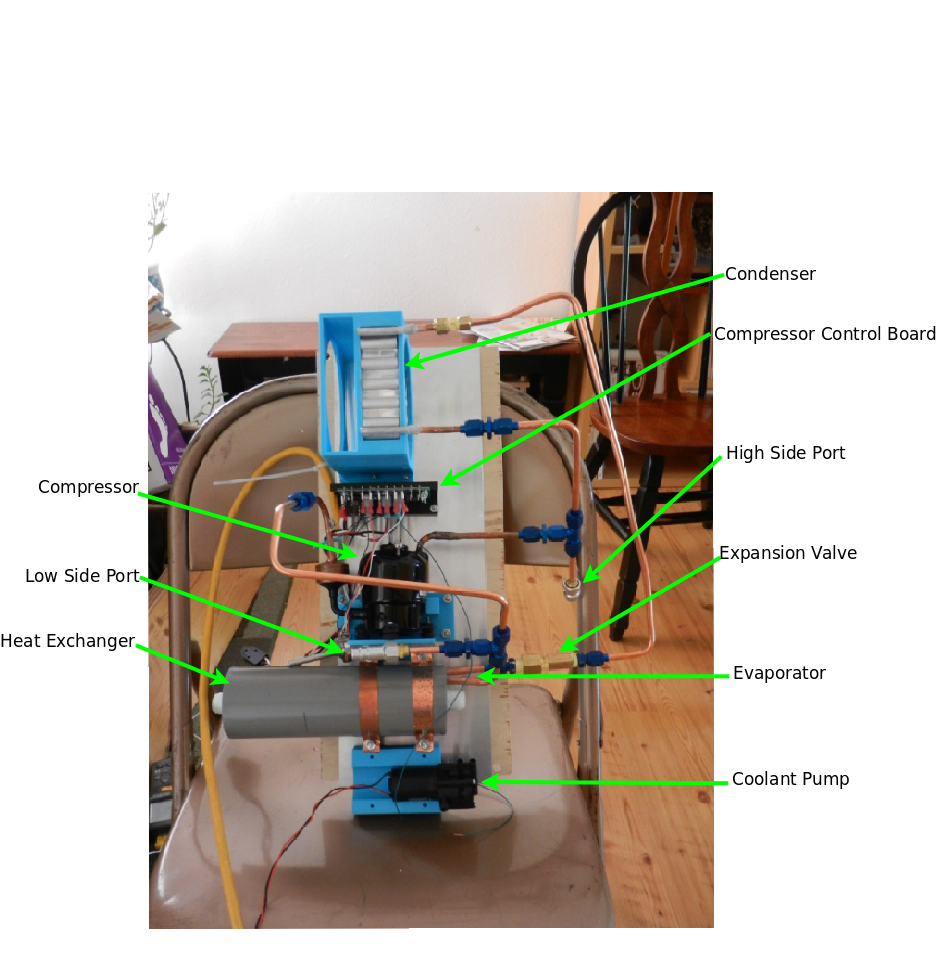
09/20/2015 at 23:09 • 0 commentsThis part of the project turned out to be quite a challenge! In my past project logs I have said that I am going to be using refrigeration to cool the liquid flowing through the shirt. The refrigeration system has only four main parts: the compressor and control board, condenser, evaporator, and expansion valve. The picture below is the version that worked. My first attempt failed to hold a vacuum and was very leaky. I will show the failed system later in the log.
Above: Working second version of the refrigeration system.
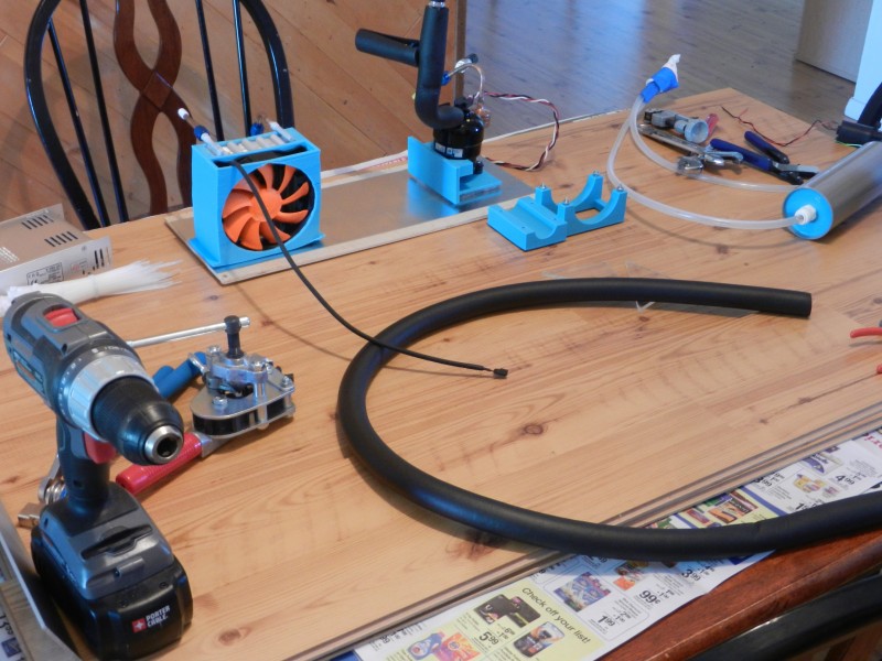
I used my 3D printer to make the mounting parts for the compressor, condenser and fan, and the heat exchanger and coolant pump.
Above: Shows my 3D printed mounting hardware bolted onto the start of my prototype backpack frame.
Here pictured above is my first failed attempt. I used AN fittings with flared copper tubing. I learned two things from this first attempt. First, I learned that you can over tighten AN fittings. Second, my problem was that I did not correctly make the 37 degree flares for the AN fittings. My flares were too small and did not correctly mate up with the aluminum AN fitting. As a result the whole system leaked like crazy.
![]()
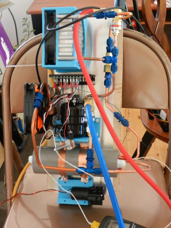
Above is the second attempt at connecting the system. I made the copper tubing flares much bigger so that the copper tube and the AN fittings mated up correctly. I also minimized the amount of connections as much as possible. Then I moved the expansion port to be right in front of the evaporator coil. I was able to get my vacuum pump to pull a vacuum on my system. Now, off to charge the system with R134A and see if the heat exchanger gets cold.
A quick note on the compressor control board. The board came with the compressor when I ordered it from Aspen Compressor. I don't have any schematics on it since it's proprietary to Aspen. I plan on building my own driver board later on down the road, but for now I am using Aspen's control board for testing and prototyping purposes.
-
Proof of Concept Cooling Shirt
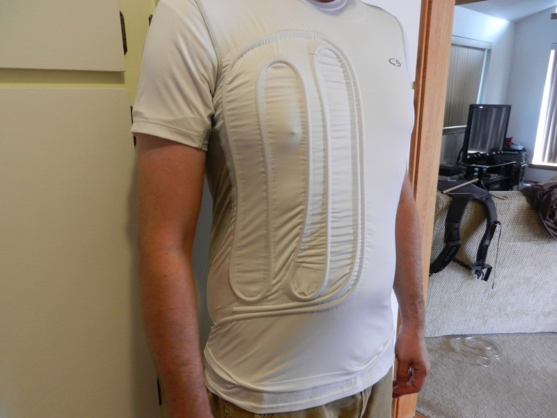
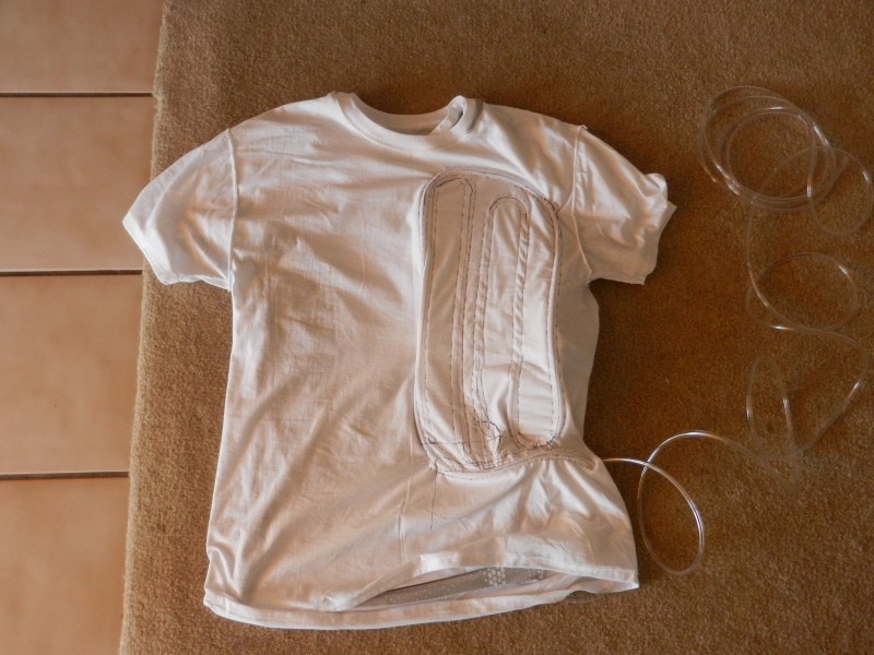
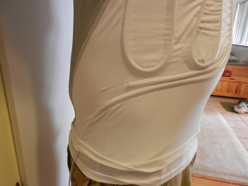
09/20/2015 at 02:17 • 0 commentsThis post is on the actual shirt containing the cooling tubing. In this step, I wanted to see if the cooling shirt worked the way I expected it to. This is why I only have one cooling loop sewn into the shirt. I constructed the cooling shirt by using a fitted outside shirt. You can see below that I purchased a Champion brand Duodry shirt. Underneath, I have a regular white cotton Haynes shirt. The purpose of the fitted shirt is to pull the cooling tubing close to the body making sure that there is good thermal contact. The cotton shirt is just to provide a way to make a channel for the cooling tubing. The tubing I used was 1/4" OD .170" ID vinyl tubing.
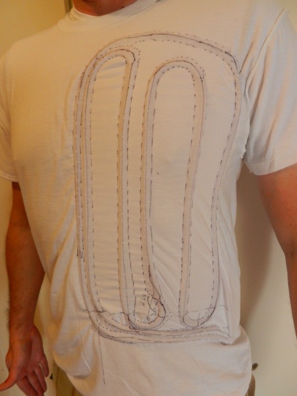
Above: One cooling loop finished for the proof of concept.
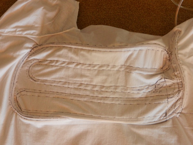
The photo below shows a close up of the inside of the cooling shirt. The tubing channels were made by sewing the cotton shirt to the inside of the fitted shirt. This created fabric channels for tubing to run through. The cotton shirt can be trimmed away leaving only the cotton channels behind. I have not trimmed the cotton shirt yet because I plan on sewing three more cooling channels into the shirt.
Above: Cooling shirt channel pattern.
Cooling tubing threaded into the fabric channels.
Close up of the cooling shirt inside out showing the channel pattern and tubing.
Close up showing the shirt right side out with the tubing entrance and exit channels.
-
Heat Exchanger
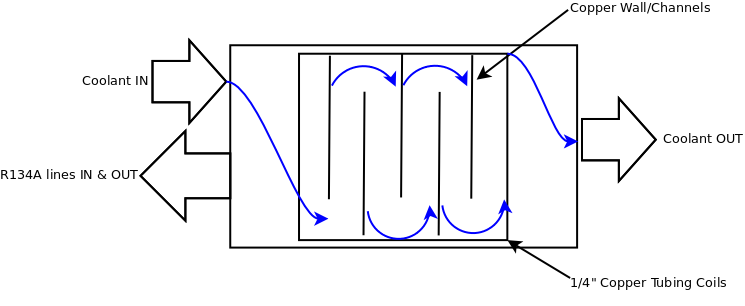
09/15/2015 at 23:03 • 0 commentsHere is how I made my Heat Exchanger, which basically has three parts: evaporator, chamber for evaporator and coolant liquid to mix, and a way to seal the chamber that will allow tubing and refrigeration connections. Below is a very basic diagram showing how the Heat Exchanger works. The evaporator coil gets cold when the refrigeration system is running. Inside, the chamber is filled with liquid coolant. The coolant is pumped through the chamber that contains the cold evaporator which mixes the coolant through the evaporator channels cooling the liquid as it is pumped out of the chamber. The evaporator coil is built so that the coolant can't just flow straight past the coil. This would be inefficient and give the coolant inadequate contact time with the evaporator coils.
![]()
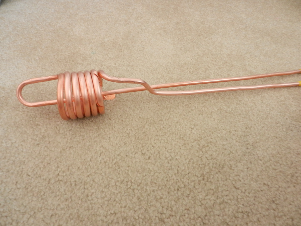
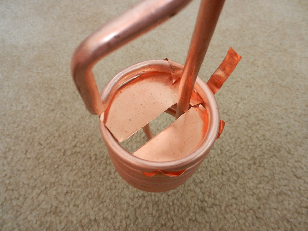
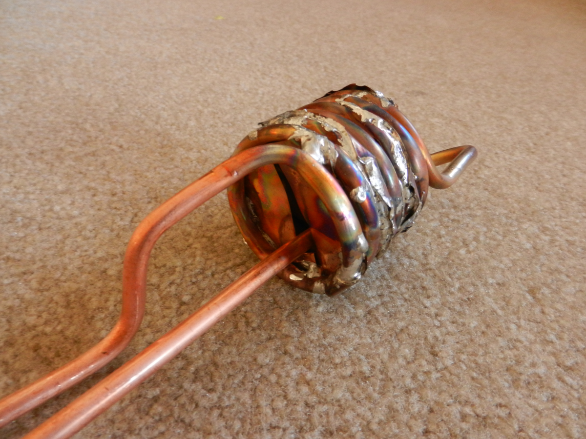
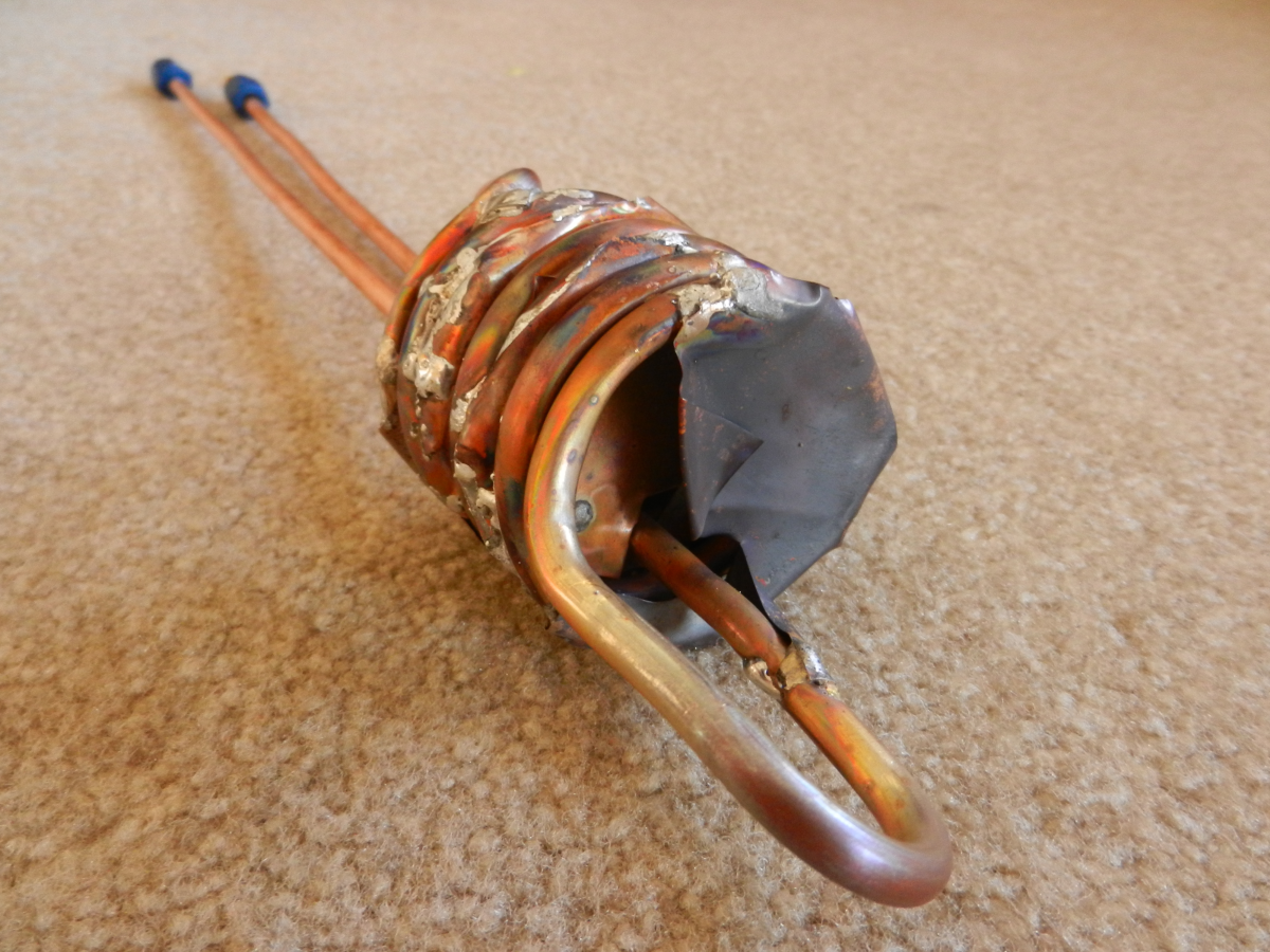
The photo series below shows how I made the evaporator coil and then soldered in the 5mil copper sheets to make coolant channels that allow the coolant to flow through the evaporator coil. This gives the coolant adequate time to cool down since it is now in contact with the coils longer.
![]()
Above is the overview of the evaporator coil.
![]()
First copper plate to make the coolant channels
![]()
Coolant channel soldered in place.
![]()
Other end of the coolant channel.
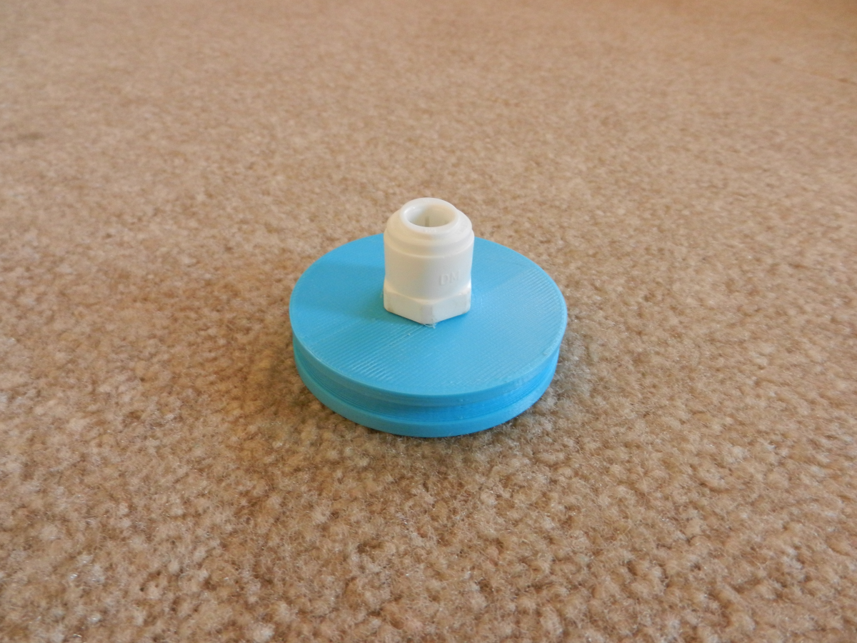
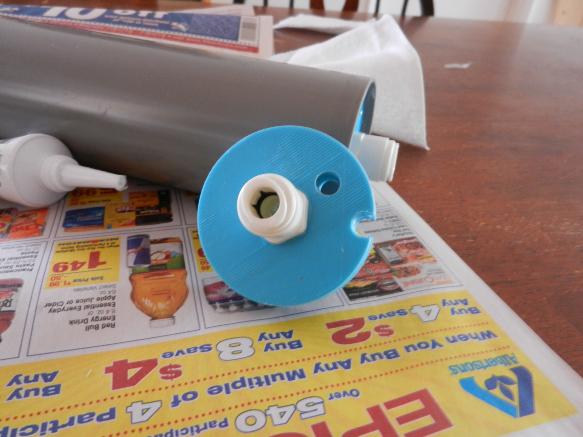
Next, I used my 3D printer and made a set of end caps.
![]()
End cap with coolant port only.
![]()
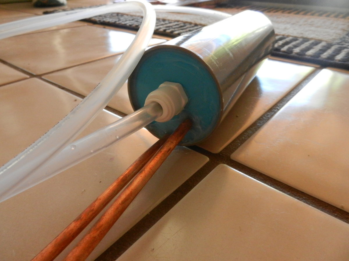
Other end with coolant port and two openings for the refrigeration lines.
![]()
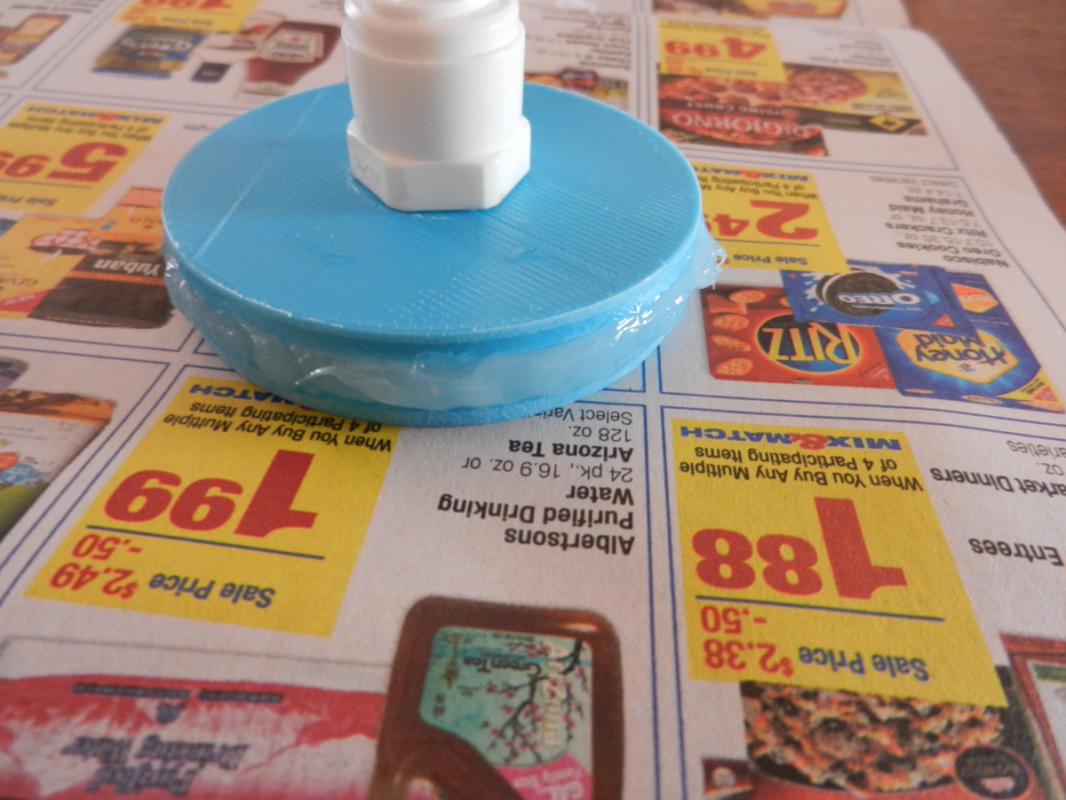
Put 100% silicone around the gasket groove to seal everything up.
![]()
End part installed and sealed with silicone.
![]()
Other end sealed with silicone.
![]()
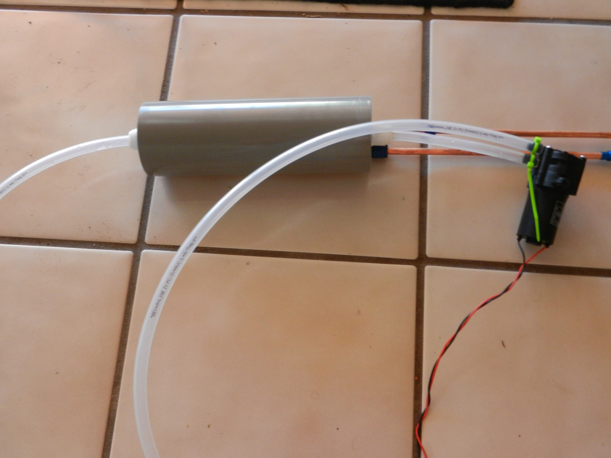
An overview of the whole system.
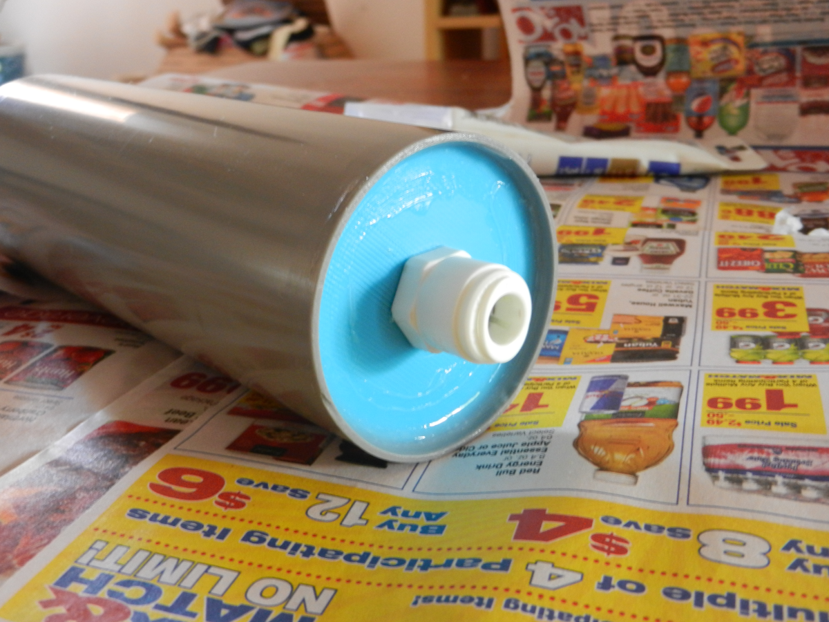
The chamber is just a G-10 high powered rocket body tube from Public Missile.
-
System design and preliminary components list
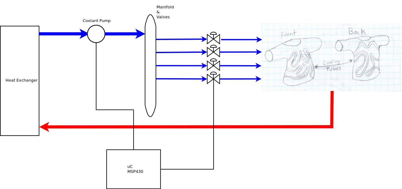
08/17/2015 at 20:08 • 0 commentsThe diagrams below are to show what I am working toward in the next couple months. I am going to be working toward finishing the refrigeration system. The refrigeration system will be integrated into a 3D printed housing that will be mounted on the backpack. I hope to also have the battery power system prototyped and running the compressor. Lastly, I hope to have some form of liquid cooling system up and running with the servo vales running.
![]()
Above shows the overall prototype system.
![]()
Above shows the battery power system. It consists of the battery balancer, charger, and boost converter.
![]()
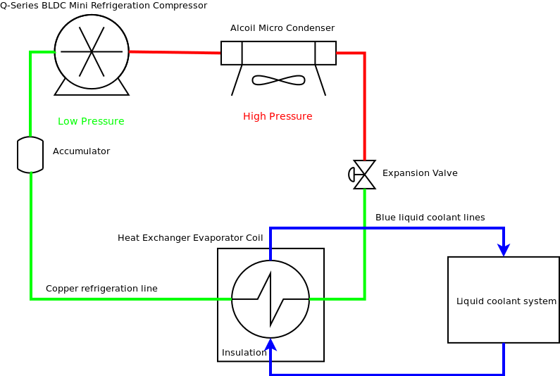
Above is the mini refrigeration system with the mini Aspen compressor.
![]()
Above is the liquid cooling system diagram with the servo valves that control where and when each cooling circuit in the shirt gets coolant circulated through them.
This is a very preliminary parts list. I will be updating this list in the coming months as I get the build going.
Part Supply Company Quantity Q4-24-5100 mini compressor Aspen Compressor 1 Micro Condenser C4x4x1.25S/CU-ST Alcoil 1 Cougar CF-V12H 1200rpm 17.7dB 12V Fan Newegg 1 2712T45 0.010" orifice McMaster-carr 1 Needle valve McMaster-carr 1 AC121 High side AC fitting SpendLessAutoParts.com 1 AC122 Low side AC fitting SpendLessAutoParts.com 1 981504 -4 union ANplumbing.com 8 581804 -4 B-nut ANplumbing.com 4 581904 -4 tube sleeve ANplumbing.com 4 Turnigy 5000mAh 20-30C Li-Po Battery Hobby Kings 2 MSP430F5152 Digi-Key 5 LT3790 Buck/Boost converters Digi-Key 2 Compressor Restrictions as stated from Aspen Compressor:
The compressor shall not be directly used for Electronics Cooling applications where the end user is a military, law enforcement or civil defense (local, regional or national) entity or personnel anywhere in the world.
-
Expansion valve and prototype coil
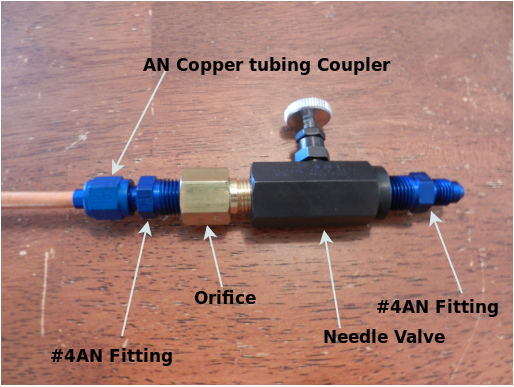
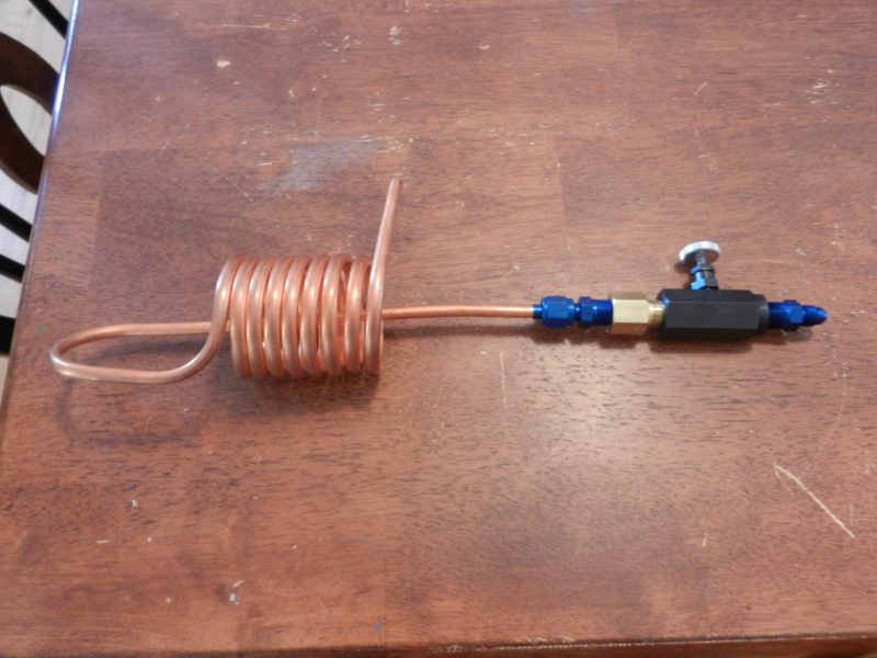
08/17/2015 at 19:11 • 0 commentsThis is my prototype expansion valve that I have made for the refrigeration system. I have incorporated both a flow control needle valve and a 0.010" flow controlling orifice. The idea behind the orifice is to make the liquid R134A spray into the evaporator coil. I added the needle valve so that I can experiment with different flow rates of R134A entering the evaporator coil. As stated in previous project logs, I am using AN fittings to connect the various parts of the refrigeration system together.
![]()
![]()
As pictured above is the whole expansion valve and the evaporator coil. I am going to make a new smaller coil that will fit better inside the heat exchanger tube. This is just to give an idea of how the system is progressing.
-
The New Plan!
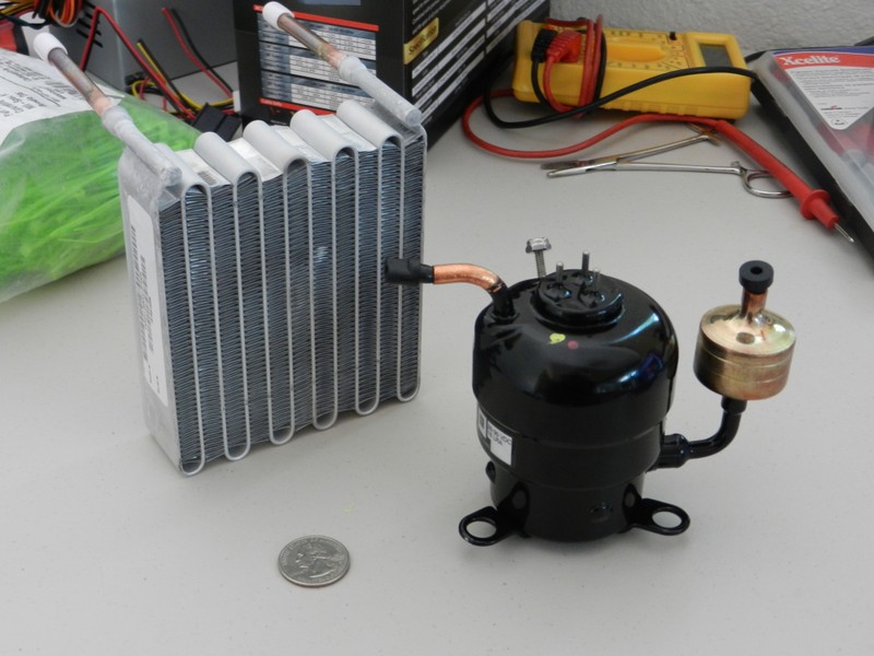
08/11/2015 at 01:17 • 0 commentsAs stated in the last project log detailing the TEC experiment, this has become a dead end for this application. I am now going with a new plan of using phase change for my source of cooling. I am going to make a mini refrigeration unit. This system will be capable of 360W of cooling power. With the mini compressor I will be putting roughly the same amount of power into the system as with the TEC's but I will be getting 360 watts of cooling power. This will be a vast improvement in power efficiency because I will not need to run the compressor all the time to reach my cooling temperature goals. The mini compressor is going to run 24V with a max current consumption of 10amps. The picture below shows the mini compressor and the micro condenser. I am going to use R134A refrigerant.
![]()
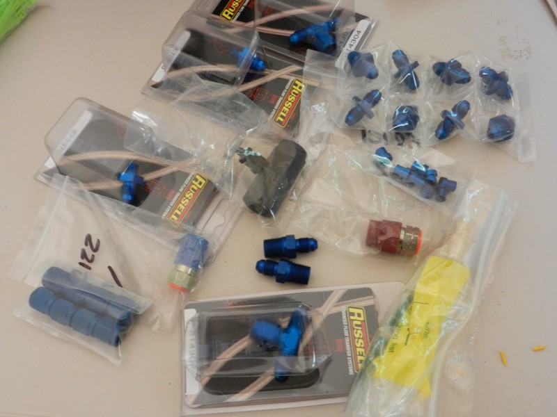
In an attempt to get away from the complexities of HVAC brazing I have decided to use AN fittings to connect up the refrigeration system. The picture below shows the AN fittings that I am going to use.
![]()
-
TEC Experiment Failed
08/09/2015 at 21:47 • 0 commentsThis project log is an overview of a TEC experiment I performed. My experiment was a quick test and not the most elegant way to run a TEC. I wanted to see if this plan was going to pan out without investing a huge amount of time. First, I made a copper coil with an aluminium plate solder/brazed to the copper coil. This did not go very well but I think I got it to work.
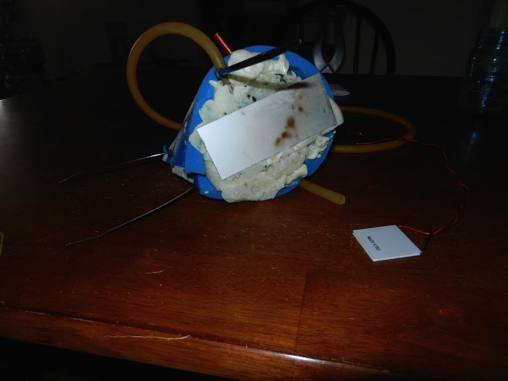
![]() The point of this cooling coil was to attach the TEC to the bottom of the aluminium plate and that would make the copper cold which would make the water flowing through the coil cold. The next step was to insulate the copper coil. This was done by using expandable foam and an insulating foam pad wrapped around the outside.
The point of this cooling coil was to attach the TEC to the bottom of the aluminium plate and that would make the copper cold which would make the water flowing through the coil cold. The next step was to insulate the copper coil. This was done by using expandable foam and an insulating foam pad wrapped around the outside.![]()
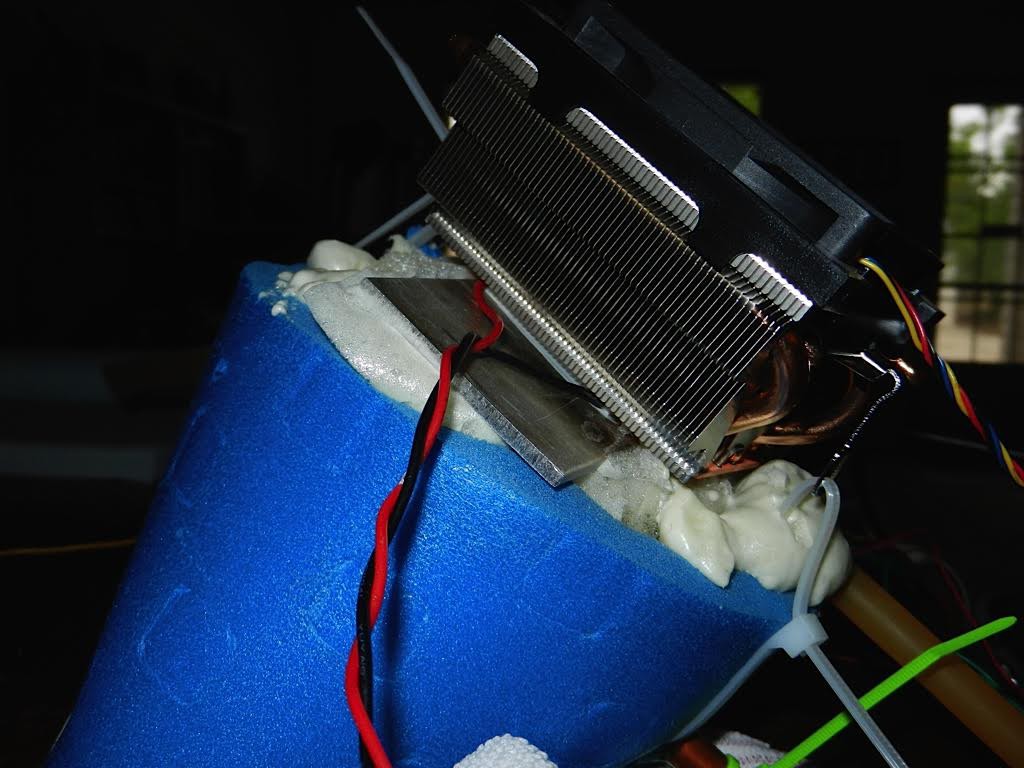
Next I needed to mount the TEC's cold side to the aluminium plate and the TEC's hot side to a heatsink. I used thermal compound on both sides of the TEC and sandwiched the TEC as shown below.
![]()
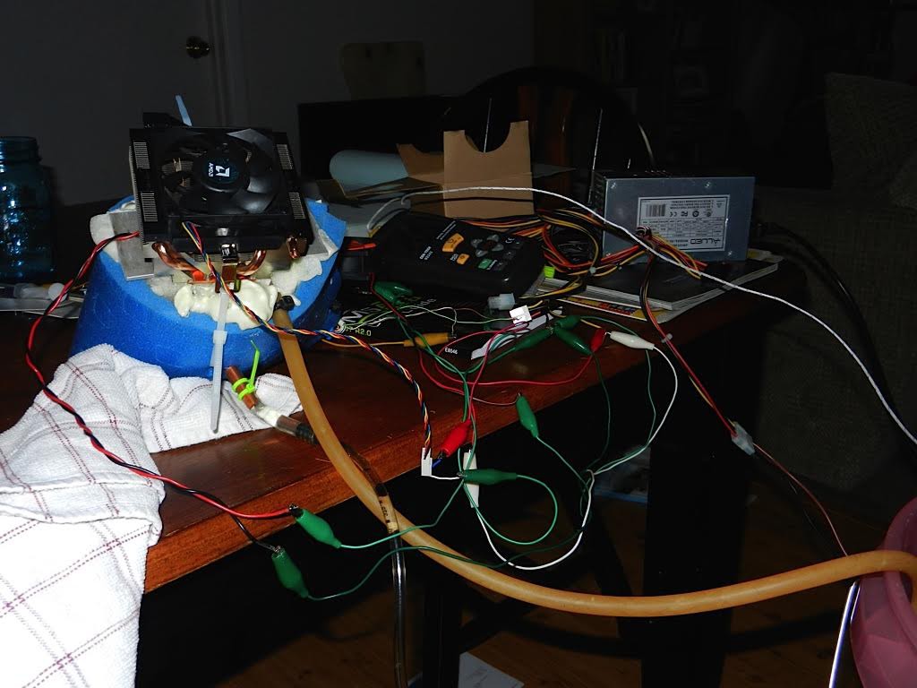
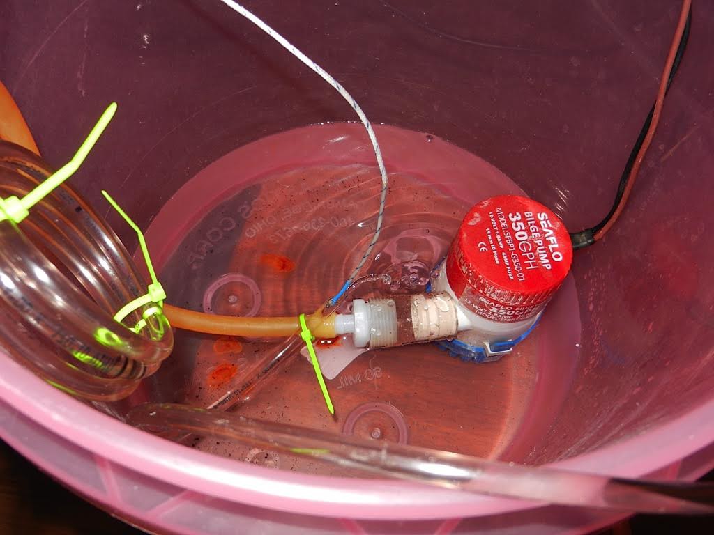
Next I hooked the whole experiment up. I used an ATX power supply to power everything. I used a 100W power resistor to limit the current to the TEC. I used the 12V rail from the power supply to power the TEC with the power resistor in series. I think this worked okay for this experiment but not for a real application as I burned a lot of power in the resistor. I used a submersible 12V water pump to circulate the water into the cooling coil. Lastly I had a thermocouple at the water outlet to measure how much the water had been cooled.
![]()
![]()
The whole purpose of this experiment was to see how much cooling I could get from a single TEC unit. The results were as I thought they would be. This experiment turned out unsatisfactory results. I was putting about 72 watts of power into the TEC, which is 12V X 6Amps. This only gave about ten degrees below ambient. This shows that they are truly inefficient devices. I am no longer pursuing using TECs for this project.
Bringing Cool Relief to Multiple Sclerosis
Cooling the core body temperature of people diagnosed with MS.
 extremerockets


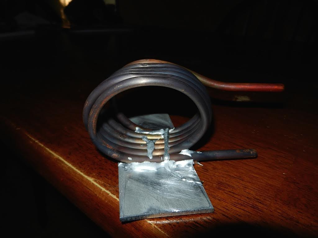 The point of this cooling coil was to attach the TEC to the bottom of the aluminium plate and that would make the copper cold which would make the water flowing through the coil cold. The next step was to insulate the copper coil. This was done by using expandable foam and an insulating foam pad wrapped around the outside.