 Eric Wiiliam
-
1Step 1
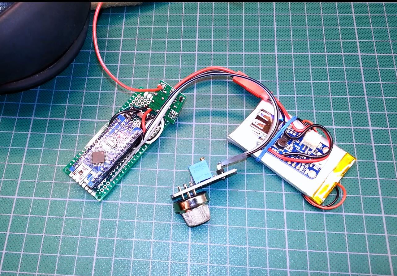
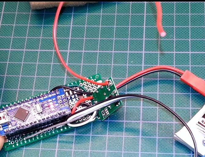
Gather all the parts listed. Fabricate the custom PCB if you wish from the supplied files (all posted on GitHub). You can use some perf-board as shown below to easily replicate as well.
Due to the limited number of connections you could also get creative with wires/jumpers dirctly to the Arduino itself...
![]()
-
2Step 2
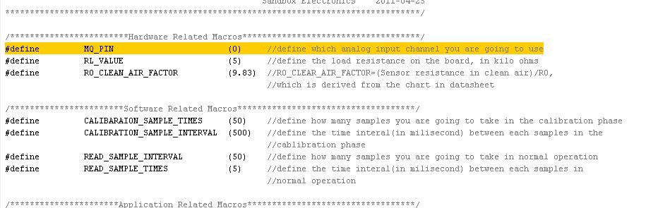
Attach the MQ2 signal pin to Arduino pin A0 as defined in the code here:
![]()
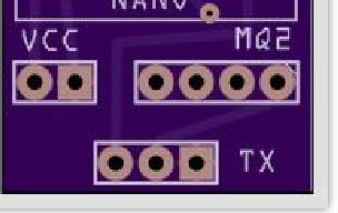
Attach the VCC and Ground pins of the MQ2 sensor to supply and ground. Using the custom PCB this is done for you here:
![]()
The fourth pin is not needed but you could use it for the digital output from the MQ2 if you liked.
You can also follow along with the video PCB assembly tutorial here:
-
3Step 3
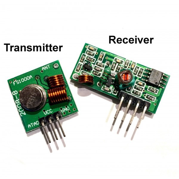
Attache the signal pin of your transmitter module to digital pin 3 on the Arduino
![]()
Save the receiver module for another project.
Attach the VCC and Ground pins for the transmitter to your VCC and ground connections.
![]()
*NOTE* Please remember to follow all applicable rules for radio transmission in your area. Some areas may require an Amateur Radio License even though the TX power is extremely low. Check your local legislation firs or substitute a transmitter on a different band if needed.
-
4Step 4
Attach power and ground to your Arduino/circuit. If you are using the PCB then it is again set out for you as VCC
![]()
-
5Step 5
Attach a 17 cm piece of wire to the antenna terminal on the transmitter. Coil it if you wish to have it more easily contained although I found this seemed to reduce the range on mine slightly.
This will give you a 1/4 wave antenna:
You can also double this for a 1/2 wave antenna length if you desire.![]()
*NOTE* Remember as mentioned in previous steps to follow all local legislation in your area for radio transmission. Always ensure you are within the rules for your local area.
-
6Step 6
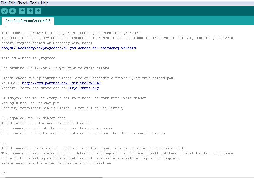
Program the Arduino with the supplied code:
![]()
Feel free to modify it as you see fit. The code is heavily commented so I hope anyone can easily understand what it is doing.
-
7Step 7
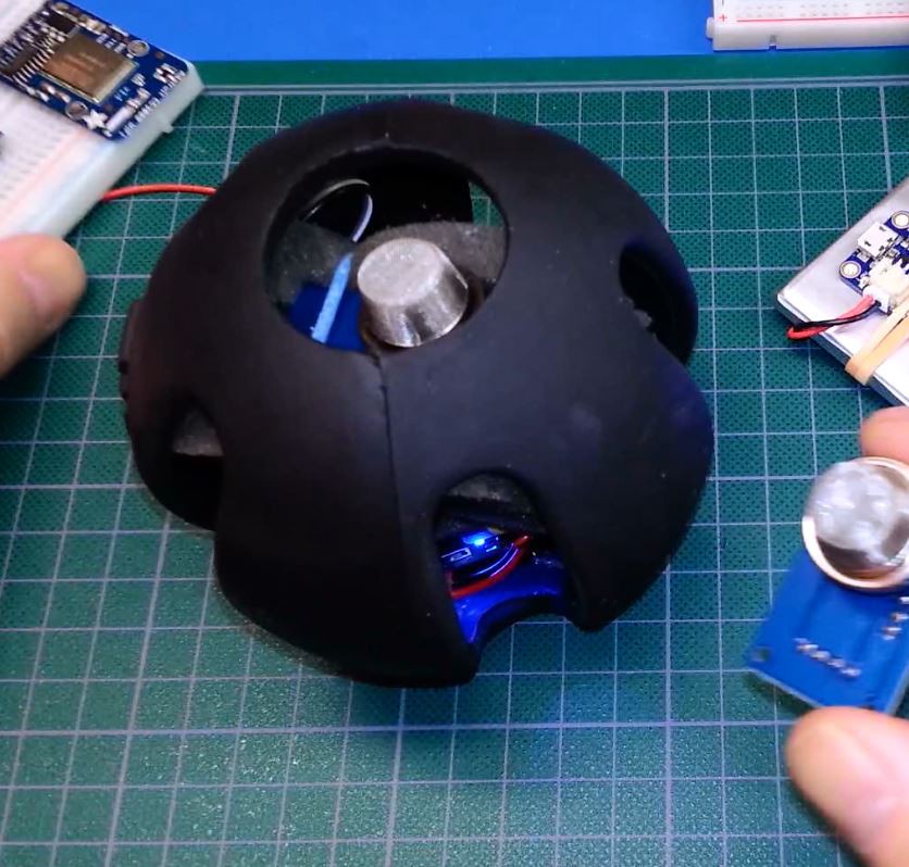
Place all your components inside the enclosure of your choice. I found the dog chew-toy a perfect fit as they are designed to take more abuse than any other enclosure I can think of.
![]()
Add padding/packing around the electronics to protect them as needed.
Here is the video tutorial of assembling the "guts" into the housing and testing:
-
8Step 8
Turn on your receiver radio and find the frequency your TX is working with- see video example for a good area to start.
Important:
You may be receiving a harmonic of the transmit frequency so others in the area may be stronger. Find the one for your transmitter and save it/write it down. If you have access to a visual representation of the band (i.e Software Defined Radio) you can quickly find the strongest frequency and not an undesired harmonic.
Use a higher quality transmit module to avoid the harmonics noted before- the ones pictured I don't think were ever intended for this purpose :)
Test and enjoy!
If you make one please share it with the world. Perhaps someday this basic design/concept will truly make a difference in the world. I can't wait to see the ones people make with actual high quality components!
Cheers
Gas Sensor For Emergency Workers
Gas sensor "grenade" that may save lives instead of taking them. The sensor can be thrown into dangerous areas to remotely report levels


Discussions
Become a Hackaday.io Member
Create an account to leave a comment. Already have an account? Log In.