Gorky
Gorky-
SDSL Alpha Complete
06/29/2015 at 14:05 • 0 commentsAfter squeezing every bit of my free time and every word on the pics flash memory I have completed all the major functions I have been planning in software.
We have two pieces of software in this project with below functionality
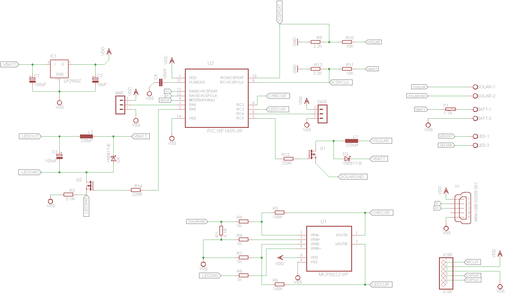
- Firmware with C running on PIC covering below functions
- Boost converter for charging and battery charging algorithm
- Driving led with constant current
- Sleeping and saving power as much as possible while checking motion sensor, analog sensor, solar power and usb connection whether to wake up or continue sleeping
- Supply status and configuration based on received USB hid data. Saving configuration to PIC's flash memory.
- Keeps log of battery condition, charge and send them over USB.
- Control panel software with Java running on any platform with JVM and usb host.
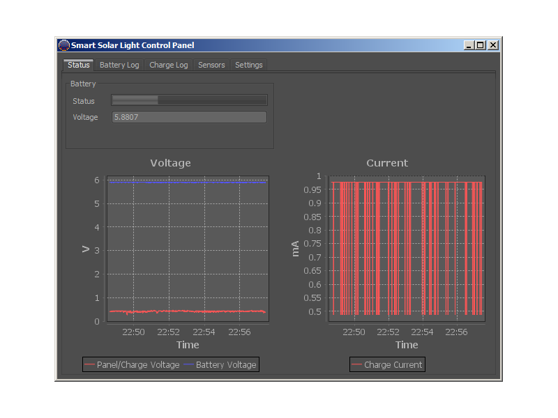
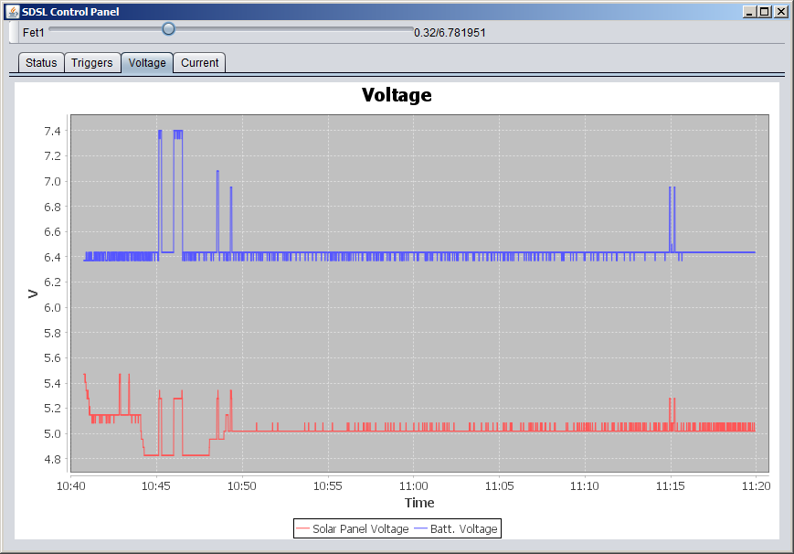
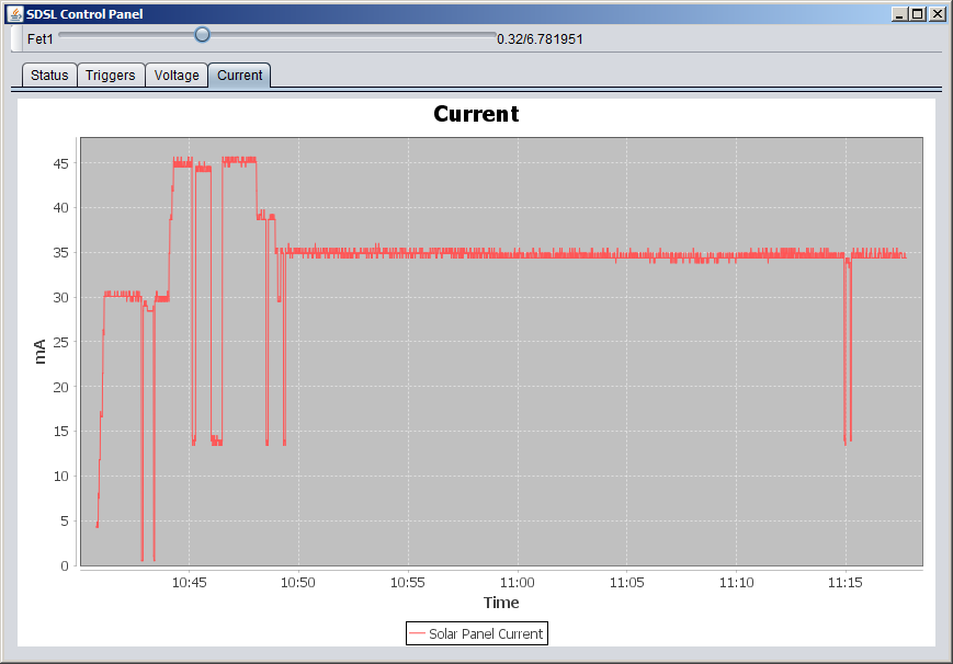
- Displays battery, panel and charge voltages and charge current
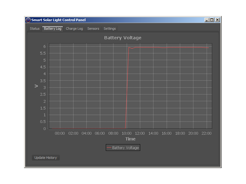
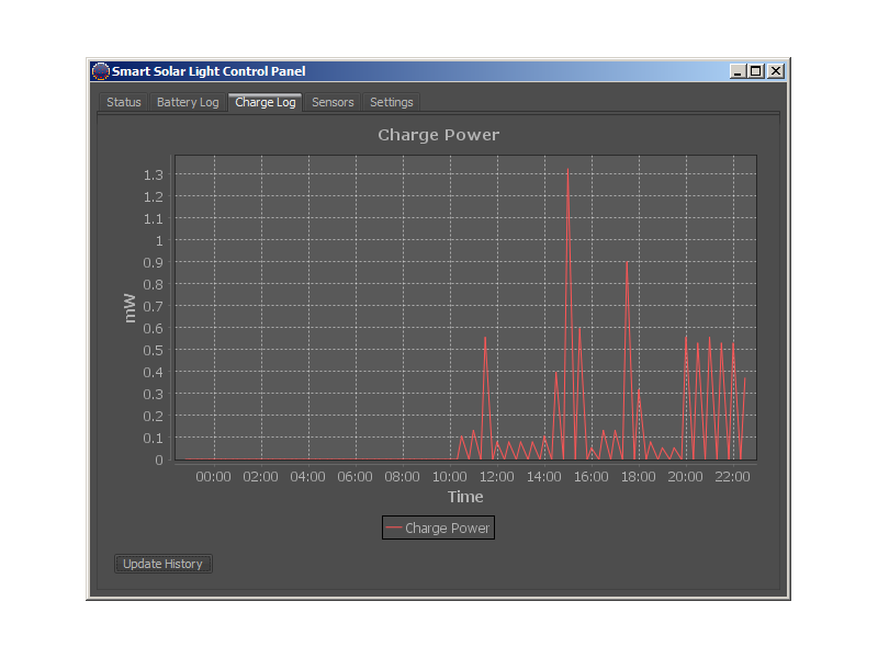
- Displays battery and charge log
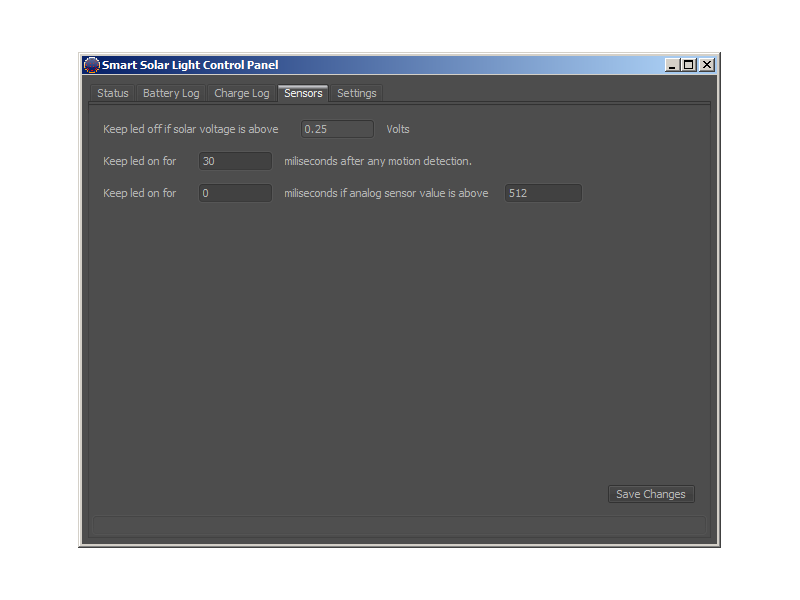
- Configures device displaying configuration ui and sending saved values over USB.
Aside from more complex problems of firmware and software I spent most of my time around one completely idiotic comparison mistake and another weird issue about not being able to retain configuration values in flash. I found the solution to the error in flash as well using all my google-fu in a single forum in a super little post. So long story short a certain silicon revision of PIC16f1455 cant write to its flash while working at 48 Mhz which is needed for usb to work. At first was a real disaster for me as the whole point of usb was to send and store device configurations. But then I found a solution which was to get the config values, detach usb module, slow down to 4 mhz store config values and then attach usb module. So after save device gets detached for a while but firmware and software handles that. Besides that newer silicon revisions do not have this problem.
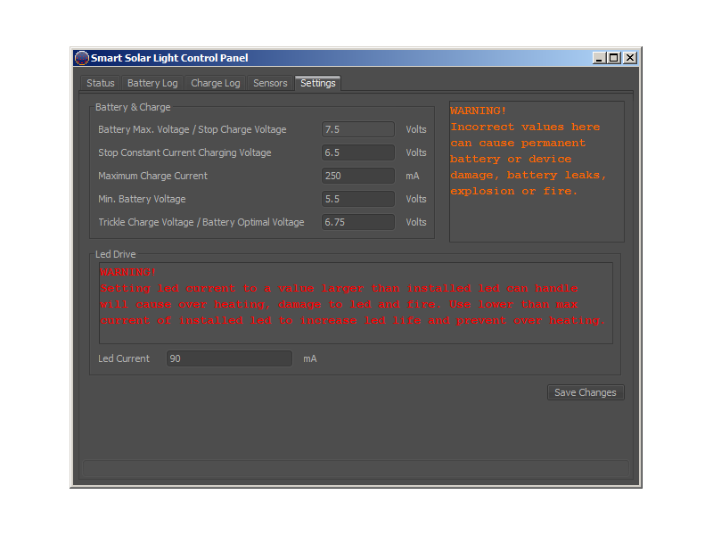
Here are some screenshot of desktop software. I will publish both firmware and software soon once I have time to start the project on github.
![]()
![]()
![]()
![]()
![]()
After all these oranges and reds if still someone manages to explode a battery with this charger or smoke a led it's completely their color blindness.
-
Board Ready
06/08/2015 at 12:27 • 0 comments![]()
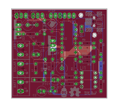
I received the pcb a week ago. Did a few tests and soldered everything on. Everything works happily. Off course a realized a couple of design issues but no show stoppers. Around the power input it got really crowded. Needed to push the caps around a bit and squeezed the inductor in the middle. Voltage divider resistors I have in stock, had slight fitting issues. Terminals I had in stock covered the power labels and I have realized it wasn't a great idea not to put polarity labels as well. ICSP pins are too close to mcu socket and doesn't make it easy to plug pickit3 directly on the board. Used another pin header to ease debugging. Still everything turned out to be far better than I expected.Also spent massive amount of time trying to come up with a compact case suitable for 3d printing. I failed so many times and got really frustrated. I tried to
- Minimize model size to allow printing with small 3d printers
- Power terminals, usb and sensor pins are accessible
- Panels can get maximum sunlight while battery stays as cool as possible
- Motion sensor and light is placed reasonably allowing them to function.
- Assembling parts is possible and relatively easy.And I couldn't come up with anything that makes sense and fits above criteria to a certain level. So I think I will stick with my initial plant design and try to improve it later. I already spent a lot of time on this.
So now I am trying to finish the software. Fixed the constant current output for led. Had problems sending floats from pic to java.Solved that. Desktop software and mcu share configurations but having problems with storing configuration in flash. PIC16f1455 doesn't have an eeprom but a high endurance flash for that purpose. It seems I still need a bit of reading to do that. I skipped it for now. I am focused on building the main program which
- Charge if enough current is available
- Turn on led if human presence detected and it's dark
- Sleep or consume minimal power if there's no human presence or power to charge
- Wake up when conditions change
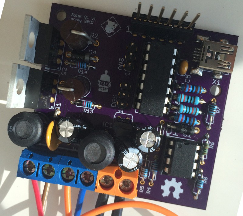
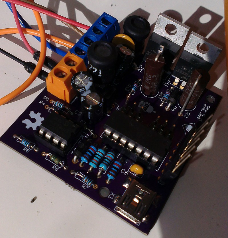
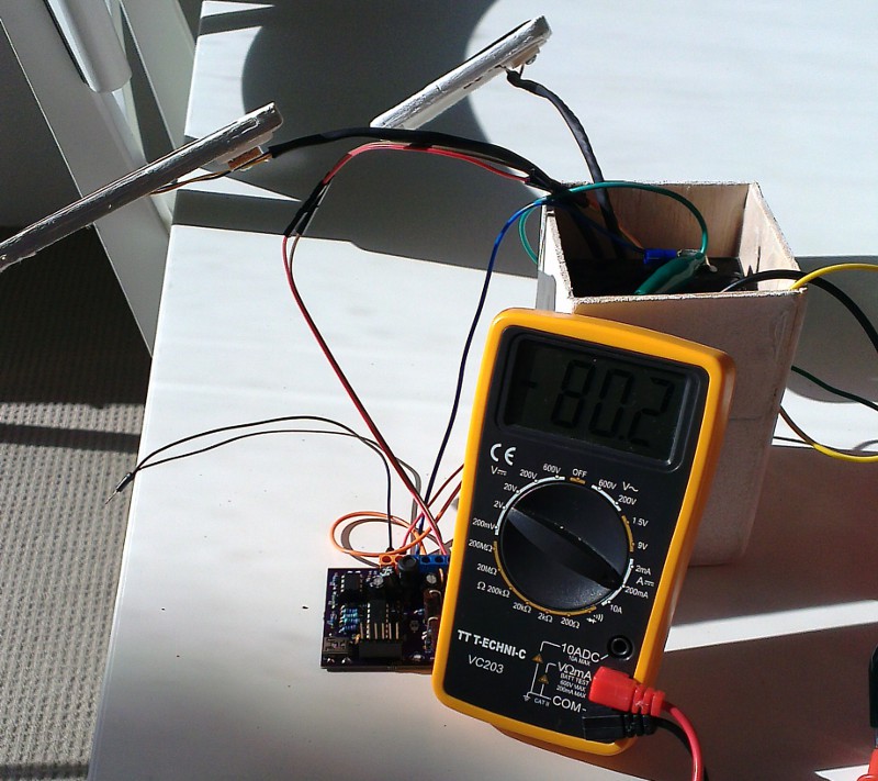
Trying a couple of methods especially around sleep and wake-up or slowing down the pic considering digital and analog sensors. USB doesn't make things easier at this stage. Here is another image of assembled board and initial charge tests.![]()
![]()
-
Shapes and Shades
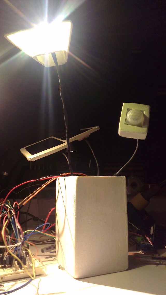
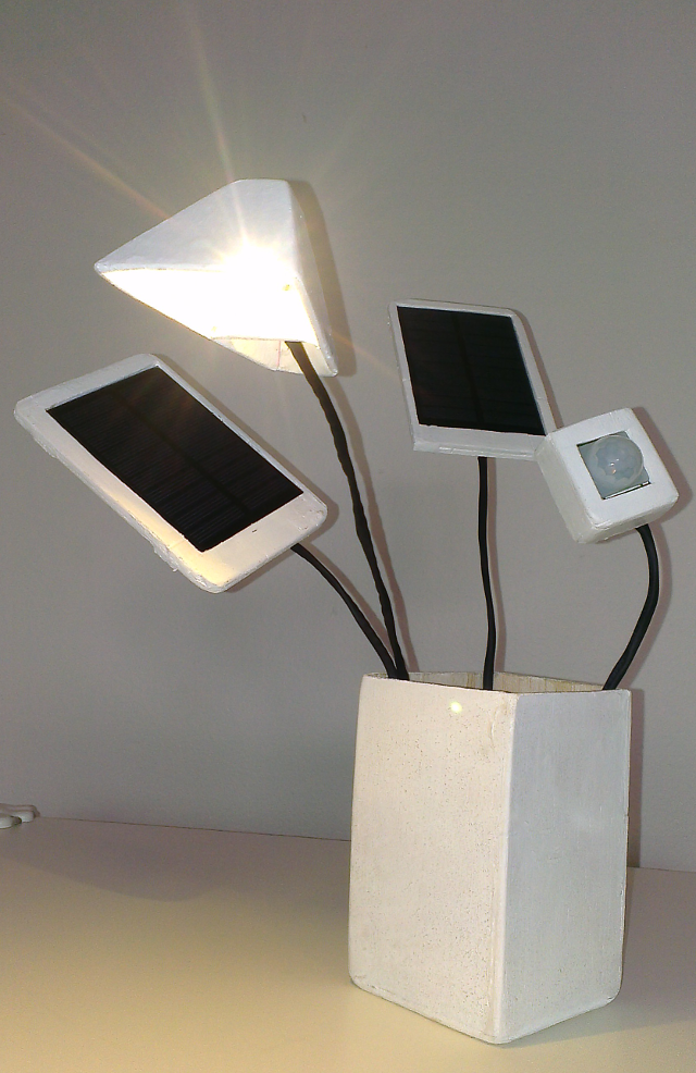
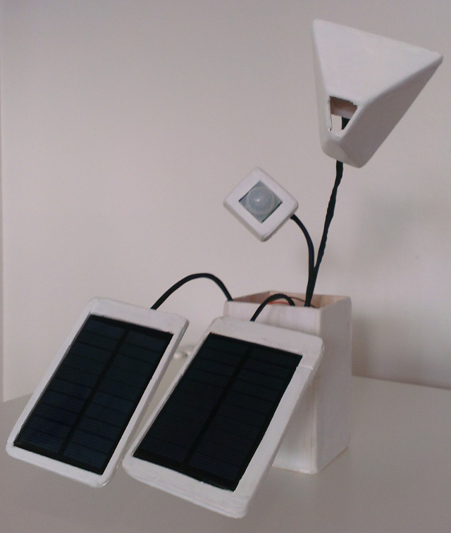
05/20/2015 at 12:29 • 0 commentsWhile waiting for the board to arrive, started working on the shape of the lamp. I really want to come up with something super simple and solid but wanted to try a few things before that.
I plan to get some parts 3d printed or laser cut but before that I needed some solid stuff to see how design ideas are working. I was really tempted to get a 3d printer but ...
Any ways so for the following first prototype design I used 1.25mm copper wire, 4mm (diameter) black heat shrink tube and salvaged cat5 twisted pairs. Parts like panel holders, base and light are cut from balsa wood and glued with a glue gun. Also applied a layer of varnish and acrylic paint on it. They still need some finishing but they served they purpose of illustrating a couple of design ideas. I put the 1.25mm wire and twisted pairs into heat shrink to connect panels, sensor and light to the base. This provides great flexibility in terms of adjusting directions.
![]()
![]()
![]()
Well I ended up with something relatively easy to build and really flexible. Panels, motion sensor and light all require some degree of separate positioning for best performance and this design gives a lot of space to play. Am I happy with this design? Not really. Would really love to come up with something far simpler. But I am thinking this project as an over-engineered teaching experiment. So far I have learned a lot about batteries, panels, charging algorithms.
-
Board complete
05/12/2015 at 11:19 • 0 commentsI have made a couple of updates on the board like paying a bit of extra attention to power lines. Also made a small change in usb power connection, so device will be powered from usb without batteries.
![]()
Hope everything is all right. The board is quite big and I might have ended up with a much smaller smd design but I think this is way more easy to put together especially for makers who wants to replicate this. An smd board with wifi is hopefully something I will do next.
So what's next. I am fiddling with Bender to for a casing. Will do the first case from balsa wood if all goes well I will try to get the parts 3d printed. Yes I don't have a 3d printer. Luckily there are plenty of places available where I can get 3d prints.
-
Led Driver
05/04/2015 at 15:03 • 0 commentsSurprisingly at last I found the chance to type in a few couple of logs.
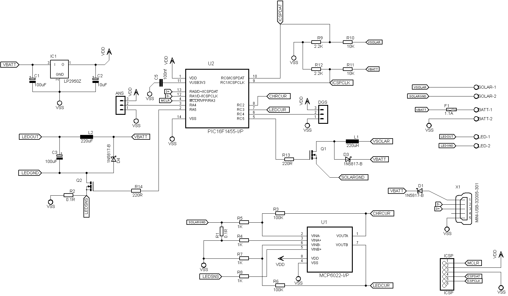
So I decided to give a shot for a constant current led driver as the project got used to switching stuff. Of course this idea led to a bunch of problems and caused me to review my mosfet choices ones again. It took me a couple of hours and a bunch of mosfets to realize there was nothing wrong with mosfets but I was just getting confused over driving them and sensing current. I changed the mosfets in any case as the previous ones I was using were smd. These new IRLZ34N fets I chose are packed in good old TO220AB, logic level and can switch a massive amount of current which is completely an overkill for this project. Their internal resistance is a bit higher compared to the smd ones I have used but still extremely small. Anyways I also completed schematics and board. Still need to review it a few times though.
![]()
Any comments or feedback is extremely appreciated as this is the second pcb I have designed.
![]()
-
materializing...
04/07/2015 at 14:11 • 0 commentsWell I guess things started taking shape especially after some Easter work. I have made a lot of trials and errors and made some changes to parts and overall system design. Will try to note down my mistakes, what I have learned and decisions made. Hope they help to someone putting together a similar project.
- I decided to use a 6V SLA battery.
- As in this project weight is not a big deal
- SLA charging is forgiving, relatively easy and safe.
- Price
- 6V is kind of a sweet spot relatively easier to regulate down and up.
- I changed 3.3v ldo regulator with a 5v ldo regulator. At first I was thinking mcu will consume less if powered by 3.3v but compared to the power loss based in voltage difference in the regulator going for 5v is better. So
- Less power loss from linear regulation
- LDO I have used has max. 300mv drop out. I will keep the SLA lower voltage limit at 5.5v where lower is no good for the battery anyways. So we have plenty of volts there.
- More devices to chose from when working with 5v instead of 3.3 (such as mosfets, mosfet drivers, op amps)
- I was planning to use buck converter for MPPT. I tried buck, cuk, boost and boost-buck charging 6V SLA with a variety of panels ranging from 0.5W 6V, 2W 6V, 1W 12V, 3W 9V. And I decided to go with boost conversion. Why?
- Considering this projects power requirements lower voltage panels are more suitable as they are relatively cheaper, smaller, easier to obtain and better suited for diy (make your ridiculously high power, low voltage panels)
- Boost converter is the simplest implementation with less number of components compared to other switching topologies. Using a logic level mosfet, no extra driving circuit, charge pump or bootstrap circuit is required.
- It's winter here and it rained for 2 days which might have effected me : )
- I changed the op amp I was using to measure current to MCP6022. While being around 40 cents more expensive it has a much lower input offset voltage which allows a mA level precision current measurement. I also tried a ACS712 based current sensor but I decided not to use it because charge current will be max. 500mA in this project which means tiny loss on shunt resistor also means too little for ACS712 leading to less precision. Besides ACS712 has a 10ma quiescent power consumption which is kind of bothering for a low power project.
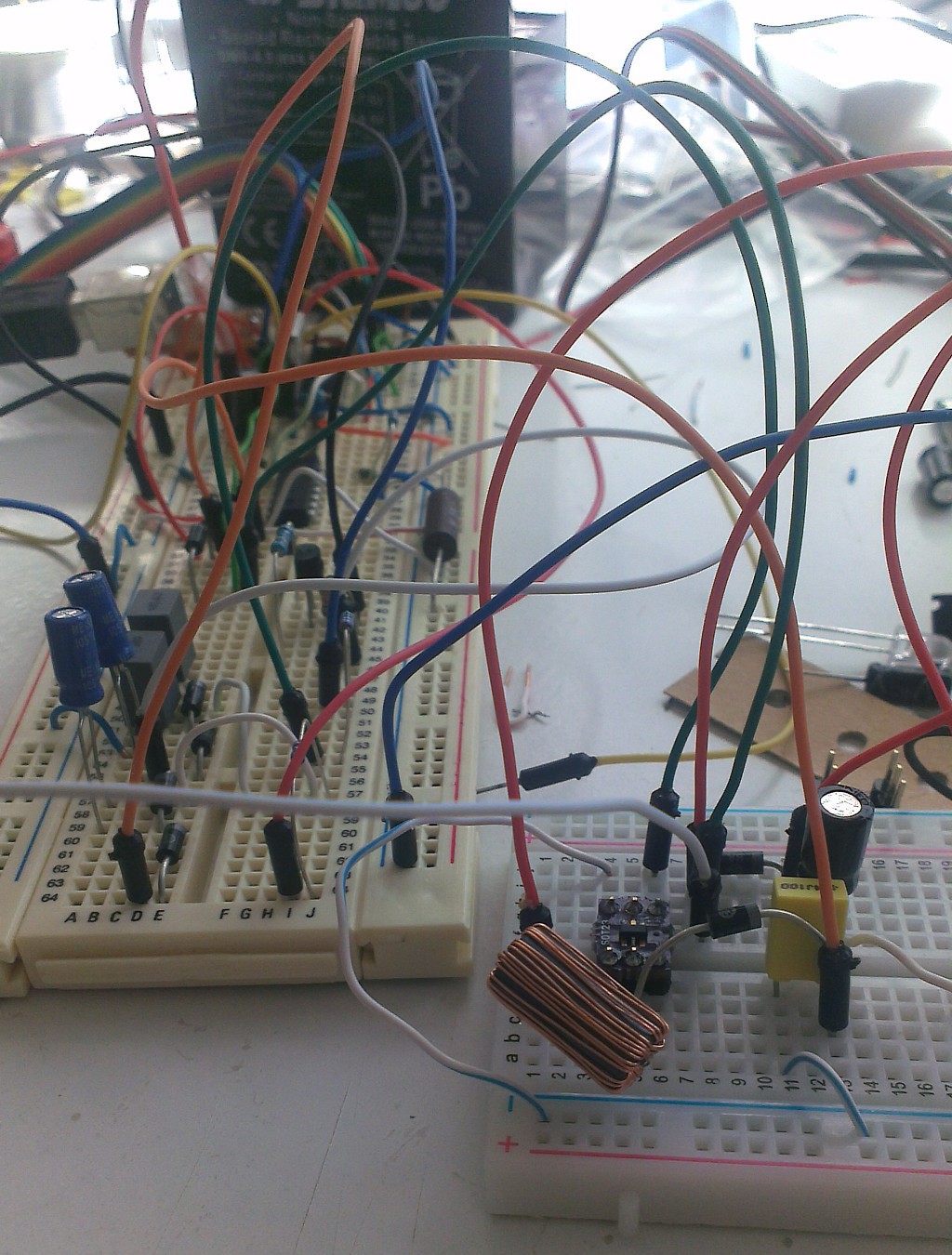
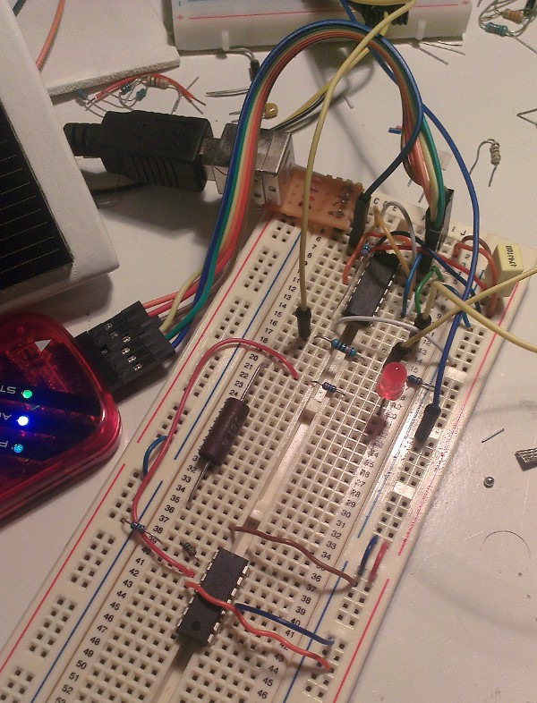
And here are some pics. Sorry for the mess as usual
Panel voltage (before boost) and battery voltage (slider adjusts boost pwm duty for debug purposes.) Peaks happened when I disconnected battery to test output voltage of boost converter.
![]()
Current, peaks represent times that I was poking in with the multimeter to check it.
![]()
Mess of board populated with torn apart implementations of different converters. And the inductor is levitating!
![]()
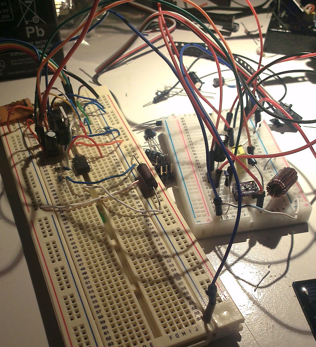
After a bit of cleaning up.
![]()
- I decided to use a 6V SLA battery.
-
Getting Ready for MPPT
03/29/2015 at 00:31 • 0 commentsIntroduced low side current sensing to solar panel which works better than I expected. For voltage measurements I have realized pic's analog input pin is leaking a lot more than expected thus resulting lower voltages than it should. It's seems the voltage dividers input impedance is too much for analog input. Well at the same time I don't want to lose any precious current from voltage divider. Will work on a voltage buffer from op amp later.
Next I will throw the mosfet IRLD120 in start cooking mppt.
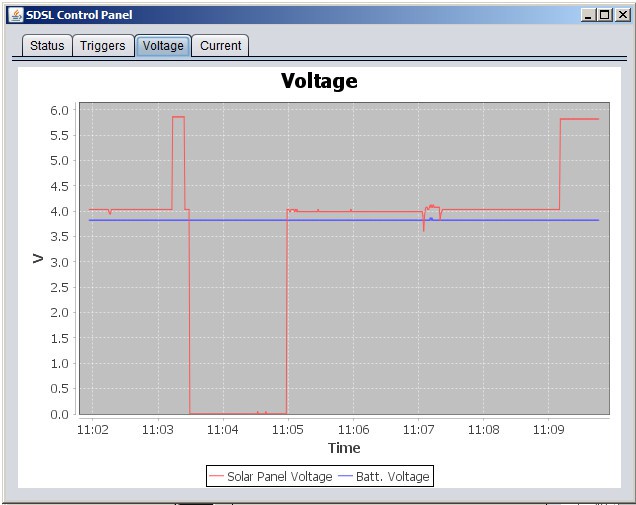
Panel and battery voltage. After 11:09 panel disconnected from battery and you can see how the voltage jumped. Diodes voltage drop is also pretty visible.
![]()
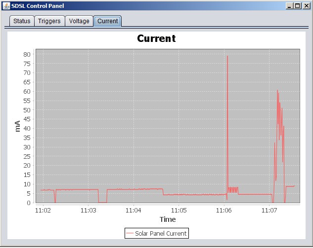
Current measured from solar panel during a few tests
![]()
-
Power status over HID
03/25/2015 at 12:17 • 0 commentsEven this is like my fourth time doing it still making the usb stack work with XC8 takes a bit of time.
- Started a c project in MPLAB X, tweaked Microchip's USB stack to come up with a custom HID device. Added a couple of utility methods mainly around USB communication to process commands from pc and reply back.
- Decided to start with shunt monitoring instead of hall-effect sensors for current measurement as it's simpler, cheaper and I am not planing to use any panels more powerful than 3W. Played a while with lm2902 op-amp and 0.01R sense resistor. Tried high side sensing first and continuously failed till the point where I completely understood why this won't happen. Low side seems to be simple and accurate. Hope it won't cause any problems once sensors are hooked up.
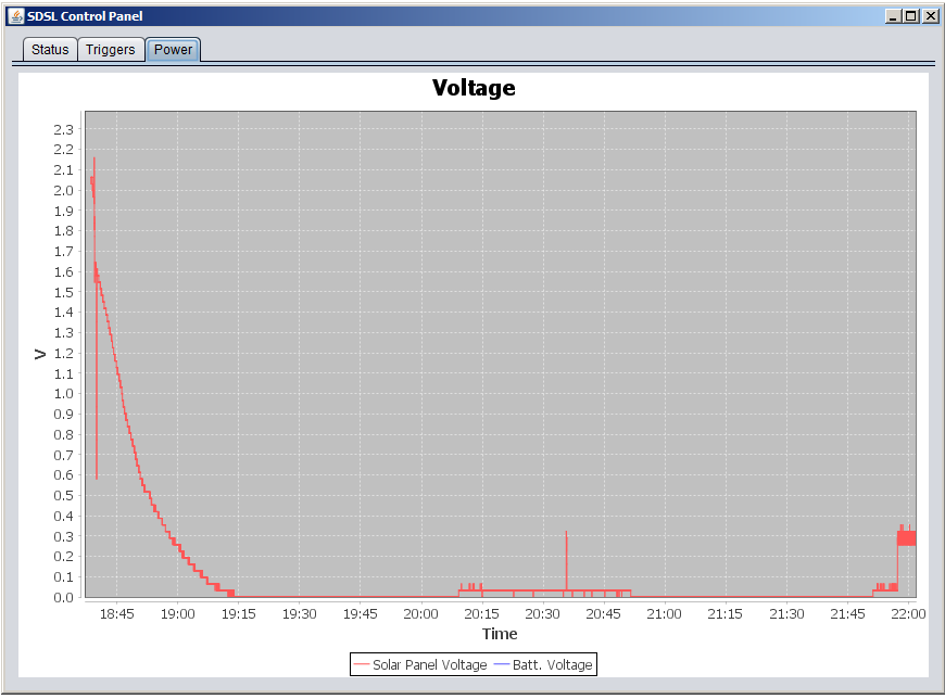
- Started development of PC control panel application which will be used for configuration and status. Decided to start with a swing based Java desktop application used Jfreecharts for fancy charting. Once I am happy with the hardware I will probably replace this with some a standalone spring web application decorated with angular js.
![]()
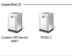
Windows' perception of my device
![]()
Java application plotting voltage from a 0.5w small solar panel sunset and turning on off rooms light and desk lamp is quite visible
![]()
Smart Solar Lamp
A solar powered led light that turns on at human presence with switch mode configurable charge control and constant current led drive