-
A Phono Stage is Soldered
03/19/2015 at 11:52 • 0 commentsPictures from construction of the Muffsy Phono Preamp.
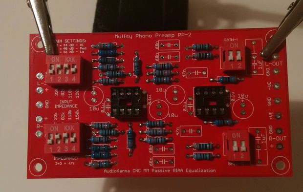
First to go in are all the resistors, as the are closest to the board. Always start with the components closest to the board. When some of the larger components are soldered in place, it will be difficult to fit the smaller ones.
![]()
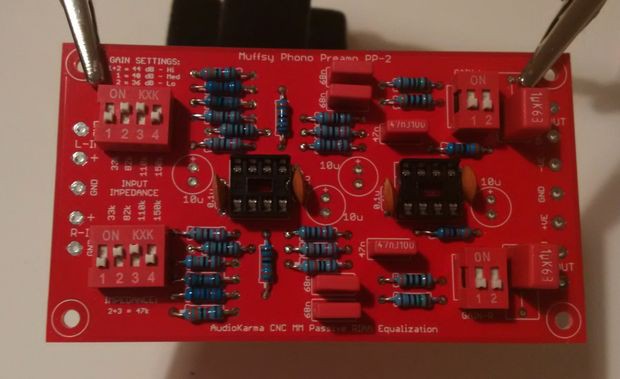
Next in line are the switches and the sockets that will hold the opamps. All of these components must be oriented correctly.
![]()
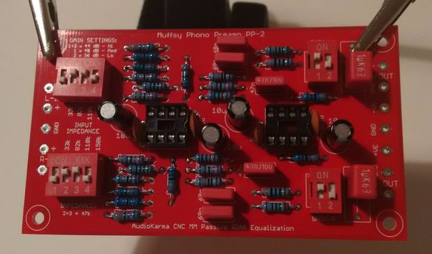
That done, it's time for the smaller capacitors. Start with the ceramic disc capacitors close to the sockets, continue with the 47nF and 68nF polyester film capacitors in the RIAA filter and end with the two 1uF output capacitors.
![]()
Finally solder the 10uF electrolytic capacitors in place, mind the orientation.
![]()
That's it, the preamp PCB is fully assembled.
-
RIAA Equalization
03/18/2015 at 17:38 • 0 commentsBy far the most significant change in the circuit is the RIAA equalization filter. It is still passive, it still sits between the two gain stages, but the values have been changed and it has shed one component.
The results are nothing less than spectacular.
Read on to find out how this circuit has a RIAA accuracy of less than +/- 0.025 dB from 1 Hz to 100 kHz!![]()
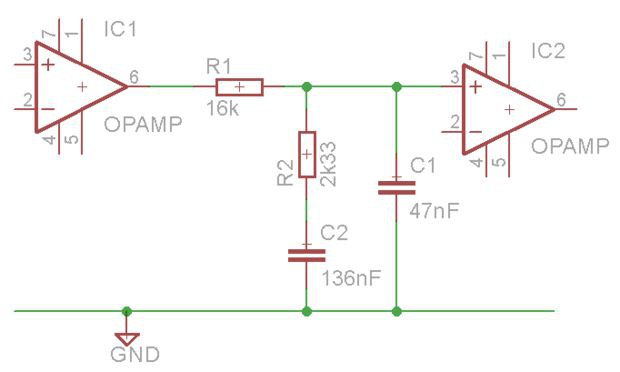
This is the schematic for the passive RIAA filter.
Why was it changed? Four reasons:
- To use standard component values
- To lower the filter resistance
- To get closer to the ideal RIAA curve
- To reduce component count
Standard Component Values and Lowering Resistance
The CNC circuit uses the following values:
- R1: 27k75 (27k + 750)
- R2: 4k03 (3k83 + 200)
- C1: 27 nF
- C2: 80 nF (47 + 33)
The Muffsy PP-2 uses these instead:
- R1: 16k
- R2: 2k33 (2k2 + 130)
- C1: 47 nF
- C2: 136 nF (68 + 68)
First of all, all the component values for the Muffsy PP-2 are completely standard. We're not moving outside of the E24-series of resistors for the whole project, and the RIAA capacitor values have been changed from three to two different values.
Second, there's one less resistor.
Third, R1, which is a part of the signal path, is 50% higher in the CNC circuit. A lower value will give less resistor noise and less attenuation of the signal.
Making a lower resistance RIAA filter makes it more dependent on the impedances before and after the stage. Luckily, we have opamps in both ends that ensures stable operation.
A passive RIAA filter will attenuate the signal nonetheless, which is why we have the first gain stage. Then the signal won't be completely lost in the filter.
What's more, the attenuation in the RIAA filter is higher as the frequency increases. Which is a very welcomed feature indeed. That means that high frequency noise is completely removed by the filter before the last gain stage.
Not bad at all, eh?
Ideal Component Values vs Chosen Values
We've dealt with three of the goals, now how about the component values that were chosen?
Component Ideal Value Chosen Value Accuracy R1 16,000 16,000 0% R2 2,326.515 2,330 0.15% C1 46.876 47 0.26% C2 136.876 136 0.5% With some careful measurements and component matching, it will be possible to match the ideal values. Doing so will give less than 0.001 dB deviation from the RIAA curve.
Performance RIAA Filter
What happens then, with the chosen values in this circuit? You're going to see that it's not at all shabby. Let's simulate it in Spice:
![]()
What we're seeing here is the deviation from the RIAA curve in milli-dB, using the components we have chosen. One milli-dB is one thousandth of a deciBel, from 1 Hz to 100 kHz.
The exact maximum deviations are +0.0227 dB and -0.0229 dB, or to simplify: +/- 0.023 dB. This is a total maximum deviation of 0.0456 dB.
Performance Complete Phono Preamp
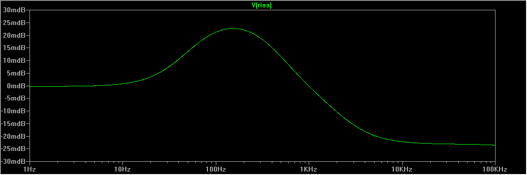
Of course, this is all academical. It is just the RIAA filter and none of the other components. So let's go ahead and simulate the full circuit:
![]()
Our deviations, from 1 Hz to 100 kHz are +0.0227 dB and -0.0235 dB. A total of maximum 0.0462 dB. The negative deviation drops below -0.023 dB at 26 kHz.
The opamps perform very well, as expected. It is safe to say that the RIAA accuracy with the actual chosen component values is +/-0.023 dB, within the audible band.
This is of course far, far below any commercial offerings, where the best usually quote +/- 0.3 to 0.5 dB from 20-20.000 Hz. This circuit falls well within +/+0.025 dB from 1-100.000 Hz!
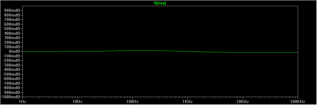
The picture above looks kinda dramatic though, but it's because the range is from -0.03 to +0.03 dB. Here's a picture with a range of +/- 1 dB:
![]()
That's pretty much a straight line from 1 Hz to 100.000 Hz. Many well regarded phono stages have deviations that would extend outside of this graph.
Summary
The Muffsy phono stage performs very well indeed. And it's all done with standard component values, so you don't have to hunt down esoteric components.
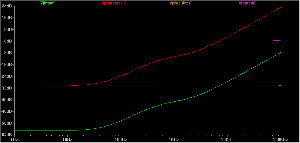
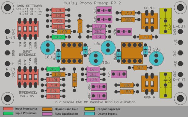
We have discussed the basic functions of the phono stage in other project notes. Now that the simulations are ready, let's have a look at them again:
- Input (green)
- First gain stage (red)
- RIAA equalization (brown)
- Second gain stage (pink)
![]()
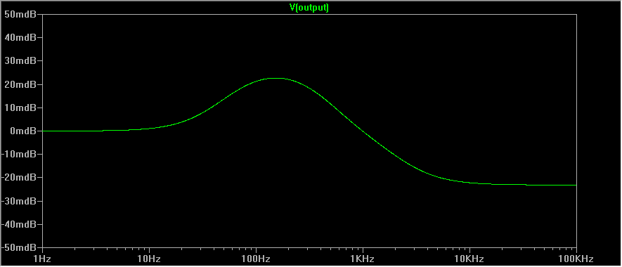
The green graph at the bottom is the input signal from your record player. This is what's on your LP, and that gets sent to the phono preamp.
The red graph is the amplified input signal. It still looks the same, but it has a higher level. That's because the RIAA equalization circuit dampens the signal, and we want to keep the signal to noise ratio at a decent level.
The brown graph is when the RIAA equalization has been applied. As you can see, it flattens the signal from your record so it's the same level across all frequencies.
The pink graph is the final result of the phono preamp. It has now been amplified, equalized and amplified again to a level that is usable for your main amplifier.
You can see that the signal has different amplification levels on different frequencies. To specify the amplification of a phono stage, we look at the 1 kHz signal. If you look carefully, you'll see that the signal has been amplified by about 40 dB.
-
Gain Stages
03/16/2015 at 22:33 • 0 comments...or how to amplify your signal 250 times!
The components colored orange, called "Opamps and Gain" are doing the amplification.
![]()
They are absolutely complete standard non-inverting opamp gain stages. The PSU inputs are bypassed (blue components) to both filter the input power and prevent opamp oscillation. These are actually very important, something that can be seen very clearly here.
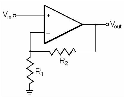
What about the amplification then? The schematics of the gain stages look like this:
![]()
Let's have a look at the first gain stage, the one at the left. These are the resistor values:
- R1: 100 ohm
- R2: 3k3 ohm
The gain for this stage is ~31 dB.
The original CNC circuit uses 3k32 ohm as R2. Replacing it with 3k3 ohm, which is more of a standard component value, makes it easier to find and buy the right resistor.
The second gain stage, the one on the right, is a bit different. R2 is still 3k3 ohm, but R1 is two resistors in parallel that has a 2-way DIP switch to select between them. In this circuit, the two resistors are 150 and 300 ohm. This gives the following values for R1:
- Both switches set to ON: 100 ohm
- Switch 1 set to ON: 150 ohm
- Switch 2 set to ON: 300 ohm
The gains for each of the three settings are:
- 100 ohm: ~31 dB
- 150 ohm: ~27 dB
- 300 ohm: ~23 dB
To get the total amplification of the circuit, add the dB values and you have the total gain. Except... The passive RIAA filter has ~18 dB loss so we have to deduct it from the total. (The RIAA filter will be discussed in another log note)
Long story short, with the variable gain settings we get these (approximately) gains:
- 44 dB
- 40 dB
- 36 dB (this one is a bit closer to 35 dB though, but 36 dB looks nicer ;-) )
In layman's terms, with the highest gain setting, the signal is just about 250 times higher than when it entered the preamp. An average signal of 4.5 mV will be amplified to over 1 V. This puts it in the general CD-player/DAC output area.
With a total gain of about 250x, and considering that the input signal is so weak, a phono preamp needs to be really quiet unless you want to listen at noise at two hundred and fifty times higher than it was to start with. Luckily, the CNC Phono Preamp does a brilliant job in this department. It is dead quiet, when it comes to noise.
After having gone through all that, the phono stage has variable gain. This is actually quite useful, as it can be used to match your turntable signal level with your other input sources. Think of it as a volume control with three fixed presets if you like.
-
Input Overvoltage Protection
03/16/2015 at 21:54 • 0 comments![]()
This circuit has a relatively high gain, as is expected when you want to amplify a 2-5mV signal to 1V or more. High gain means high sensitivity, and we want to make sure that no specks of dust or any other sudden cartridge signals won't create a large THUMP!
That's what the green resistors called "Input Protection" are there to prevent.
For more in-depth information, Analog Devices has a PDF that describes the whats and the hows of input overvoltage protection.
-
Input Impedances
03/16/2015 at 14:39 • 0 commentsAlthough the default input impedance for most cartridges is 47k ohm, many are reporting that other input impedances are giving better results.
The standard CNC circuit has the following impedances, selectable with a four-way DIP-switch:
- 18k, 33k, 47k and 62k ohm
These values are quite sound, but having the possibility of paralleling up to four resistors should give a few more useful options. The four values above don't give many other options though.
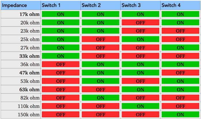
How about using these values instead?
- 33k, 82k, 110k and 150k ohm
Let's see what we end up with:
![]()
(Values in bold are equivalent to the original CNC circuit)
There are a few options that are too close together to be useful (which I haven't listed in the table above), but we get quite a range to choose from nonetheless.
Well, that's settled then. New input resistors all around for the evolved CNC circuit.
-
Etch Your Own PCB
03/16/2015 at 13:18 • 0 commentsUse this PDF (it's actually two of them, one with the copper layer and one with the silk screen) to etch your own PCB:
http://www.instructables.com/files/orig/FUO/CYCE/I760TVUB/FUOCYCEI760TVUB.zip
The PCB is single-sided, and uses a full ground fill. There's not much copper that needs to be etched away.
-
Going Small
03/16/2015 at 12:57 • 0 commentsOne of the goals with this project is to make a smaller PCB. In the process, the signal path will be shorter and the board will fit in a smaller enclosure.
I'm starting with this:
![]()
And I'm ending up here:
![]()
Next I'll talk about the considerations and design choices.