-
Building the CNC - Audio Wiring & Summary
04/14/2015 at 09:10 • 0 commentsCompleting the Build
This concludes the build of the Muffsy Phono Preamp. Soon you'll be spinning records like never before.

A short recap is in order. So far we've:
- Soldered the phono preamp
- Found a suitable enclosure
- Decided on a power supply
- Built a back panel
- Mounted the parts in the enclosure
- Wired the power
- Chosen the input impedance
- Set the gain
We have even learned a lot of stuff along the way, and should be able to change the circuit to suit our needs.
We're not completely finished yet, we need to input the sound from the turntable and output the amplified and equalized signal.
These are the parts involved:
- The phono stage
- Shielded audio cable
- Back panel with:
- Two female RCA panel connectors for input
- Ground screw for input
- Two female RCA panel connectors for output
Back Panel - Grounding
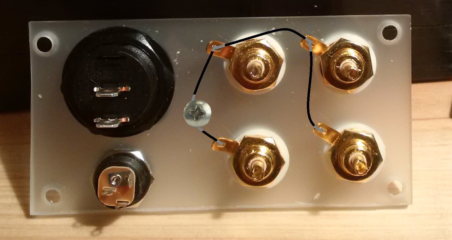
The first thing we'll do is to make sure all the grounds are the same for every RCA connector and the ground screw. Connect them all together as shown in this picture:
Back Panel - Input and Output
These are the cables that connects the phono stage. The best choice will be to use a shielded phono cable, especially for the input.
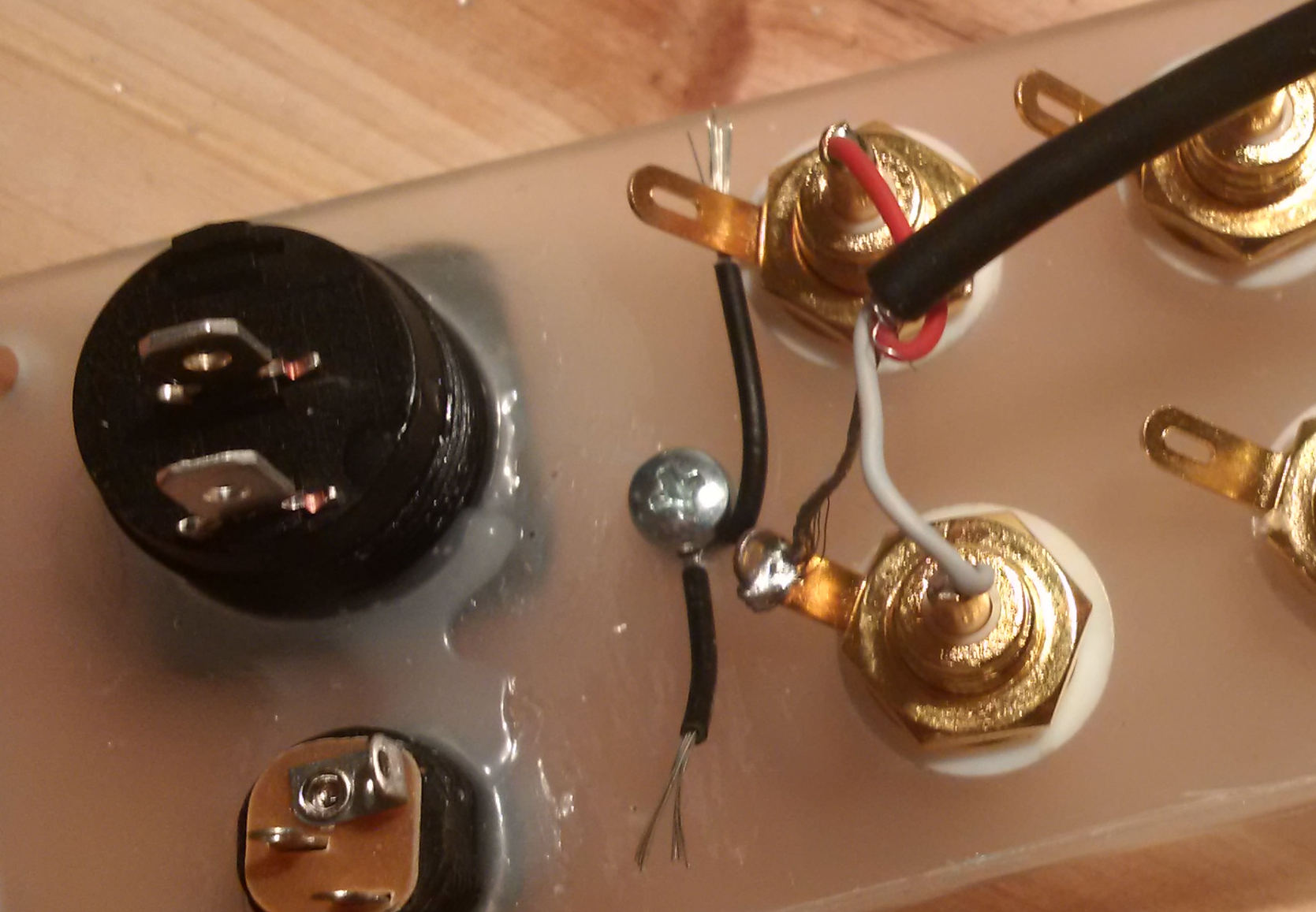
Here's how the input cable is connected to the RCAs. Connect another cable to the output, which is the two remaining RCA connectors, and the back panel is done.
Phono Stage - Input and Output
The two audio cables, input and output, that connect to the back panel must also be connected to the phono stage.
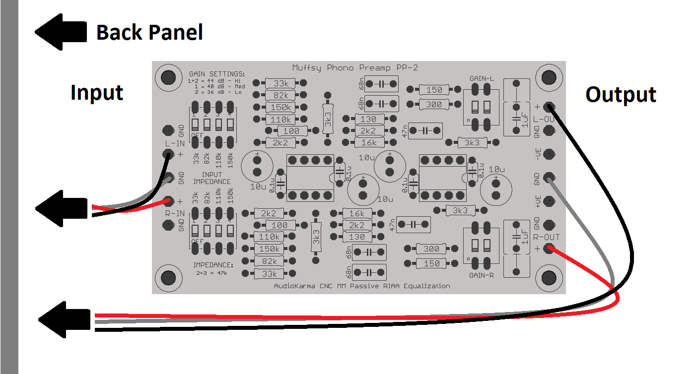
The picture below shows how to hook up the phono stage, using two-lead shielded audio cable:
The left side of the board is the input (from your turntable), the right side is the output (to your amplifier). They were connected to the back panel in the previous step, and this is where they attach to the phono stage itself.
NOTE:
Make sure that the input is closest to the back panel. You will want the input signal cable to be as short as possible. Both to keep the cabling capacitance down and to avoid unnecessary interference.
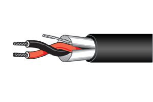
Here's a picture of a two-lead shielded audio cable:
The RED cable is always the RIGHT CHANNEL.
The GREY cable represents GROUND. It will be the shield on your shielded audio cable.
The BLACK cable is the LEFT CHANNEL. Depending on the cable, it can also be white.
Other Cabling Options
Cables can have one lead, two leads, two leads with shield, four leads (with or without shield) and many other variations. The Muffsy Phono Preamp can accomodate all these types of cables.
For the input and output, there are two connections per channel (+ and GND), with a GND connection in between. This makes it easy to find a proper way to cable your phono stage.
Completeness :-)
This actually completes our build, congratulations!
Now, go play some records!
-
Building the CNC - Power
04/13/2015 at 10:31 • 6 commentsThere are a lot of ways to power the phono stage, but they might not be too obvious as it needs a dual power supply. That's positive voltage, ground and negative voltage, in the range of +/- 9 to +/- 18 volts.
I'll give you three ways of powering your phono stage, starting with the absolutely best one:
The Muffsy Hifi Regulated Dual Power Supply
+/- 15 volts is commonly used for operational amplifiers, and that's what you get here.
The quality of this power supply is exceptional, and it must make you wonder what goes into the $1.000 (or more!) power supplies that some manufacturers will be more than happy to sell you.
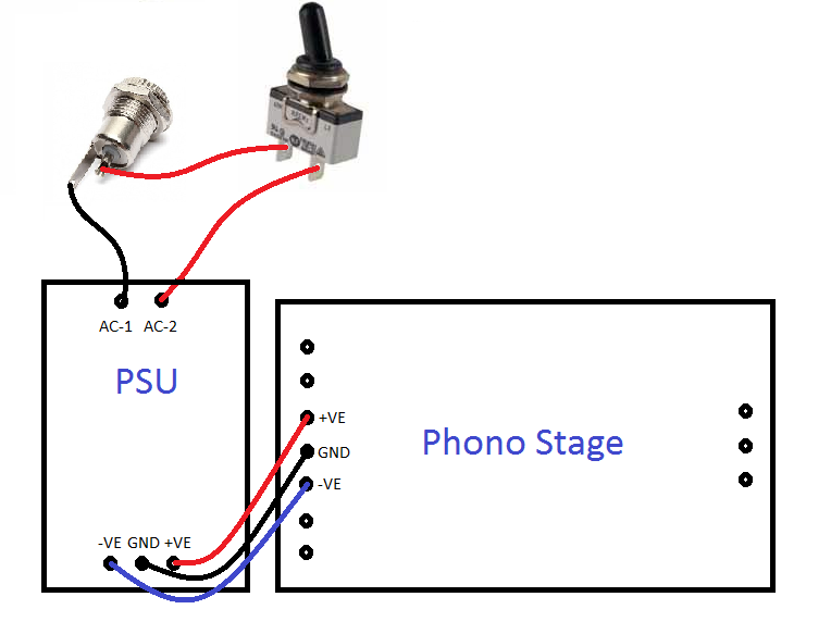
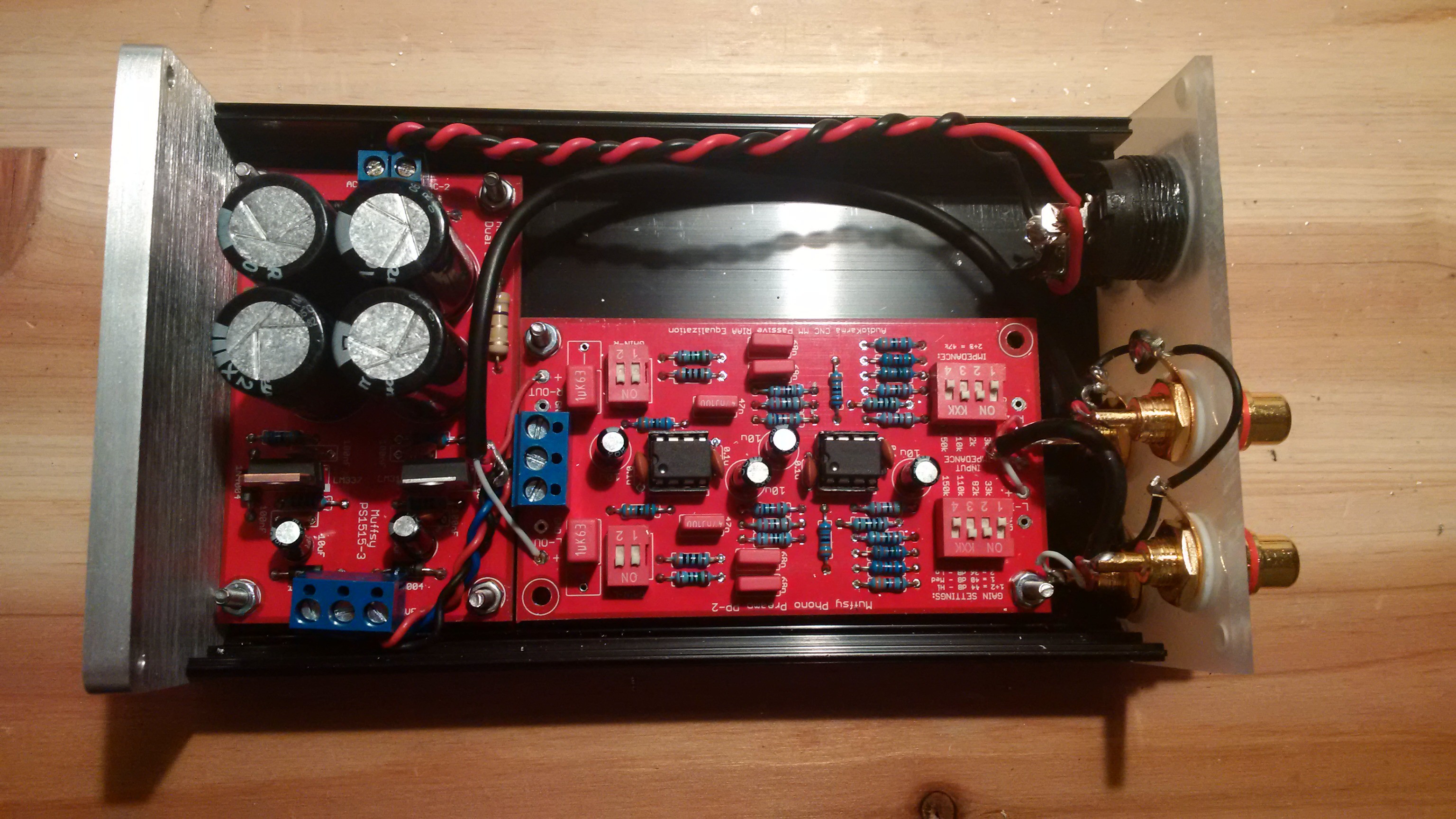
This is how you hook up the Muffsy Hifi Regulated Dual Power Supply:
The power comes from a 15-18VAC wall wart into the power connector (top left).
One of the cables go to directly the PSU, the other through a single pole single throw (SPST) power switch and then to the PSU. This is how we can turn the phono stage on and off. You don't have to worry about the orientation of these cables, as they both carry the same AC power.
NOTE:
Both power cables are live. Make sure that both the power connector and the power switch are completely isolated from the chassis/enclosure!
With power going into the power supply, you'll get +/-15VDC from it. Connect the +VE, GND and -VE on both boards, and you have power on the phono stage.
You should twist the two cables from the power connector to the PSU, and braid the three cables from the PSU to the phono stage to reduce interference.
If you want to add an LED, connect it between -VE and +VE. Connect a 1k5-4k7 ohm resistor, rated for 1/2W in series with the LED. Lower resistor value gives brighter light. (If the resistor is 3k9 ohm or higher, 1/4W can be used.)
Battery Power
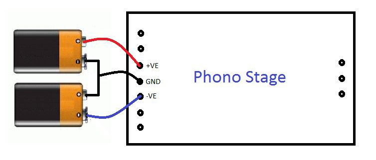
You can even power the phono stage with two 9 volt batteries, and it will run on them for weeks. Here's how, referring to the picture above:
- GND: Connect the positive side of one battery to the negative side on the other battery.
- +VE: The remaining positive side is your +VE.
- -VE:The remaining negative side is your -VE.
A suitable power switch would be a DPDT, since you need to break both +VE and -VE. Here's a diagram of the cabling with power switch:
LED for batteries will also have to be connected between +VE and -VE. The resistor in series with the LED can be from 820 to 2k2 ohm rated at 1/2W. Lower value gives more brightness.
Just keep in mind that an LED at max brightness uses the same amount of power as the whole preamp. I would recommend using 2k2 ohm and sacrifice some brightness, just to make the batteries last longer. (If the resistor is 1k2 ohm or higher, 1/4W can be used.)
DC to DC Converter
The first two options were either an AC power that was converted to dual DC, or two separate batteries. There's another way that's quite neat as well. On paper, it should be quite a lot worse than the other two. We'll see that it might be a good option after all.
I was in the position where I powered a class D amplifier with an old 19.5 volts laptop power supply, and I wanted to add the phono stage to this setup. A voltage divider was not an option, as the virtual ground and real ground would connect. Not wanting to short-circuit everything, I had to find another solution.
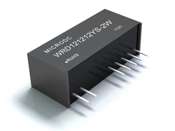
Enter the WRD isolated and regulated, twin output DC/DC converter.
It comes in different variations, and can be powered by 5, 12, 24 or 48VDC. The output will be twin 5, 9, 12 or 15VDC.
I chose the WRD241212YS-2W, because it accepted an input voltage of 18-36VDC. The output is a twin 12VDC. (The WRD121212YS-2W will accept 9-18VDC in, and will also provide 2x12V out.)
Make sure you choose the 2 watt version to get sufficient power for the CNC. The 2 watt version will power two CNC boards with power to spare, but you'll want that extra headroom.
The twin outputs are really comparable to two batteries, as they provide two independent 12 volt power supplies.
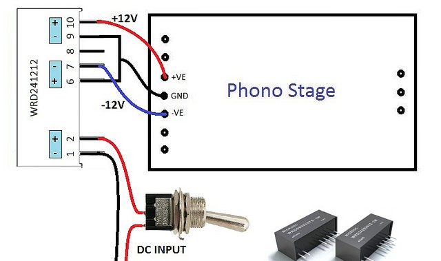
Here's how to wire the WRD, complete with (an SPST) power switch:
(The WRD PSU is much larger on this picture than it is in real life, just to make the wiring easier to see.)The output power is completely isolated from the input power. The ground connected to the CNC (which is really the positive side on one PSU connected to the negative side on the other) can be connected to the INPUT DC ground without any worries. This is really helpful if you want to trace down and get rid of any ground loops.
So why is this the worst (on paper) solution? The WRD power supply has a very high ripple. up to 50mV, which is 500 times as much as the Muffsy power supply. That is quite a bit worse, to be honest.
The phono stage's onboard bypass capacitors will filter away much of this ripple, and the ripple rejection of the operational amplifiers takes care of the rest. I have used this solution, and it is absolutely impressively silent.
If you want to add an LED, connect it between -VE and +VE. Connect a 1k5-4k7 ohm resistor, rated for 1/2W in series with the LED. Lower resistor value gives brighter light. (If the resistor is 3k9 ohm or higher, 1/4W can be used.)
(very short) Summary
The phono stage is now powered, and you can turn it on and off at will. The only thing left is to connect the audio.
-
Building the CNC - Enclosure
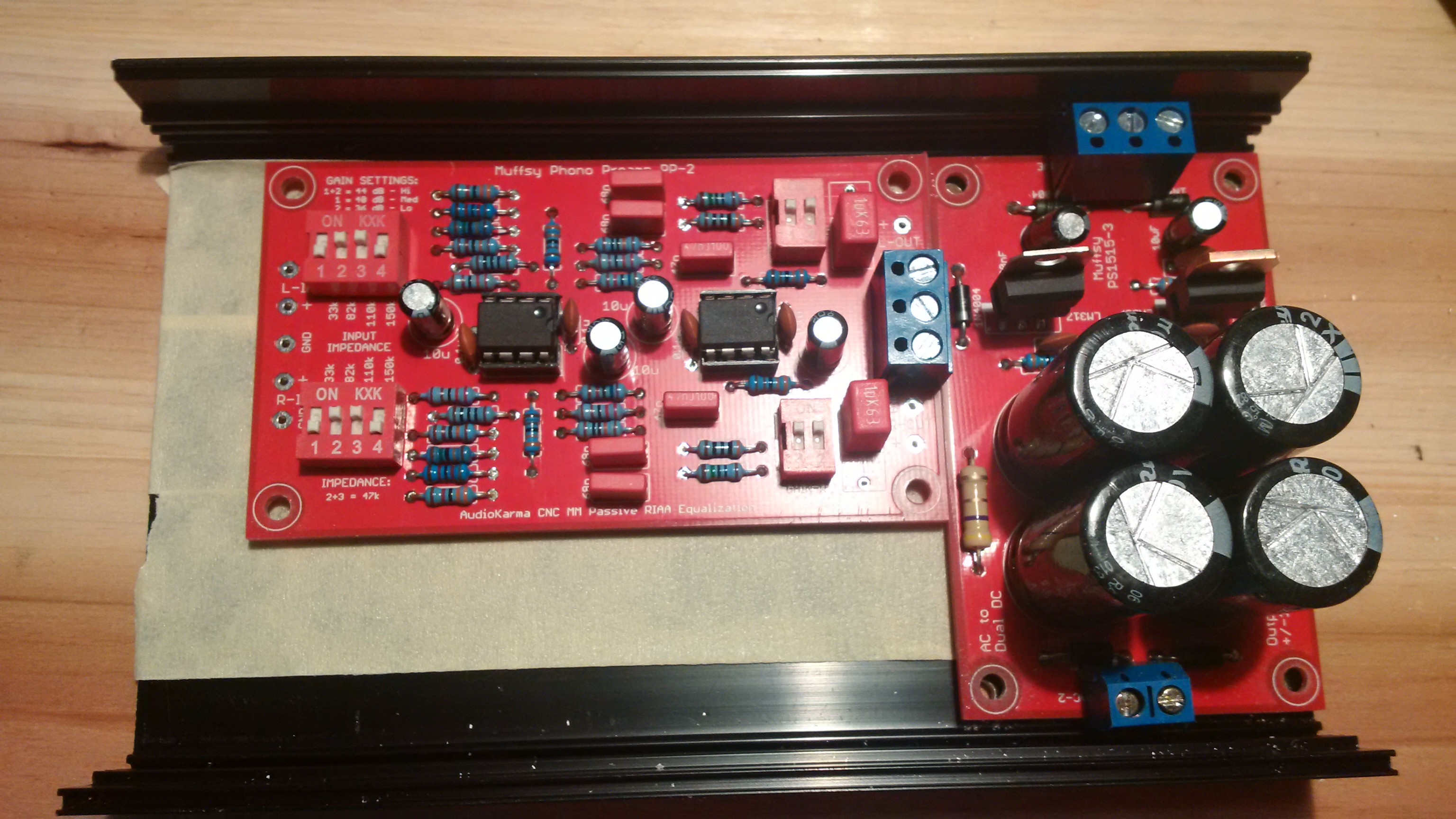
04/05/2015 at 22:13 • 0 commentsFor my CNC build, I'm using a 0905 aluminum enclosure. I have already made the back panel, hooking everything up will be covered in another log entry.
Before I go on, let's go through what I'm going to do and why.
Both boards, the power supply (PSU) and the phono stage (CNC), are going to be mounted in my enclosure. First of all, I want them to stay put and not shuffle around.
Most important though is that I don't want any of the exposed solder points touching the metal casing. If they do, there will be a number of short-circuits and the whole project will go up in smoke. (And, if I were to connect it to my stereo with no prior testing, it would most likely damage my amplifier.)
Enclosure Build with Lots of Pictures
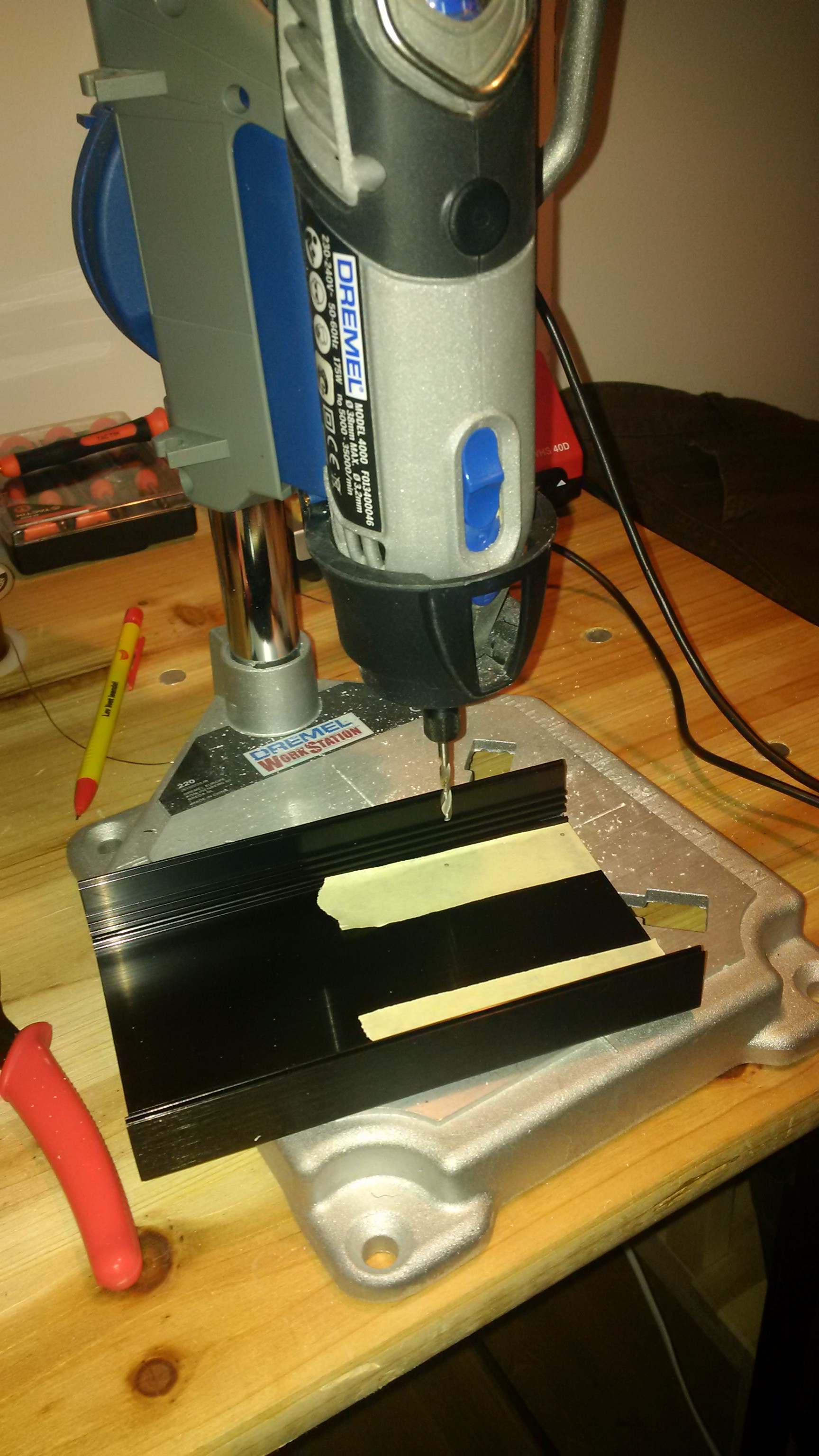
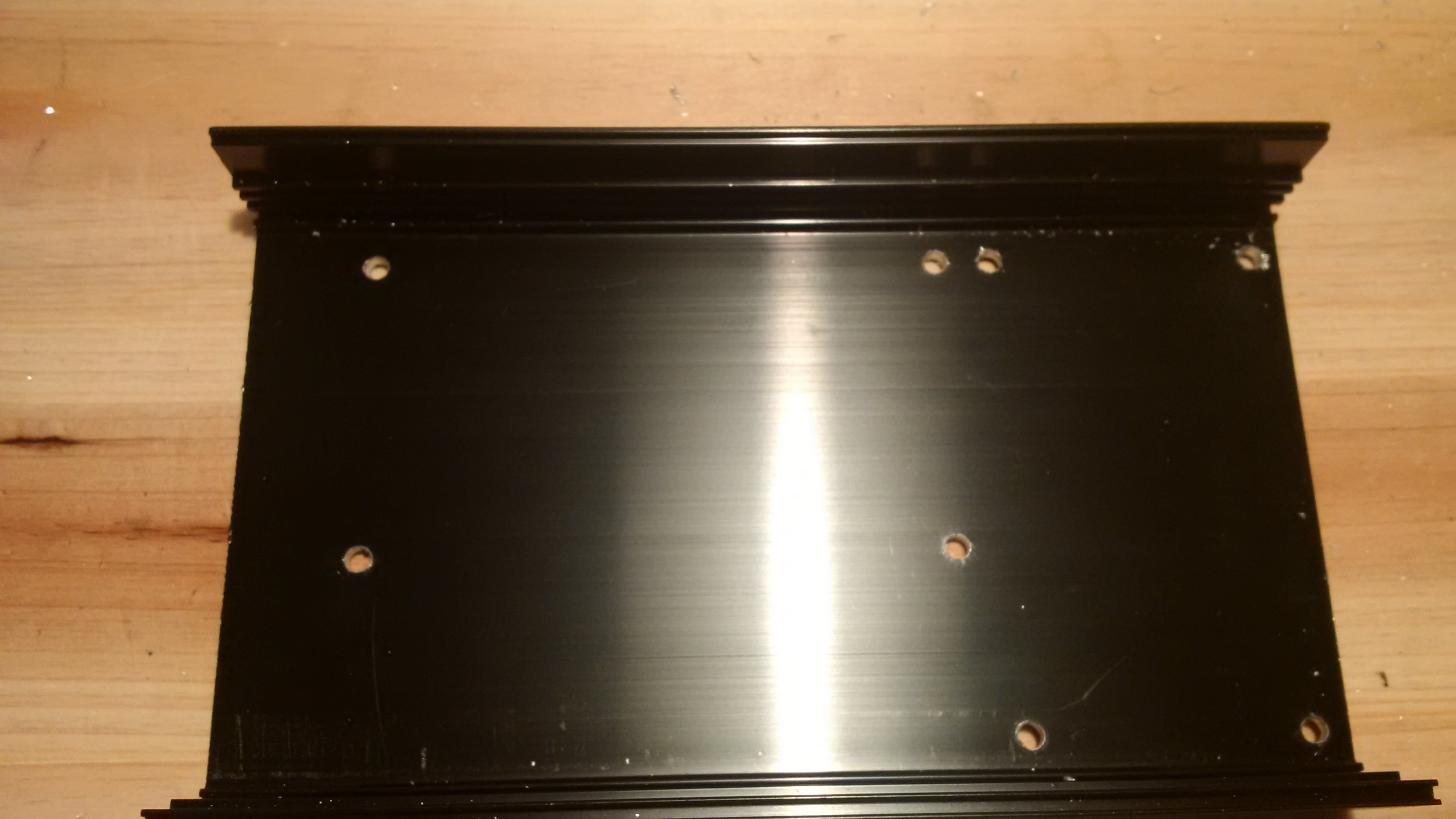
The phono stage and the power supply will be mounted with screws. I'm not going to screw them straight through the metal, so I put some masking tape in my enclosure (because it's easier to write on), positioned the PSU and marked where the holes should go:
That done, I used my Dremel in the drill press to make the holes:
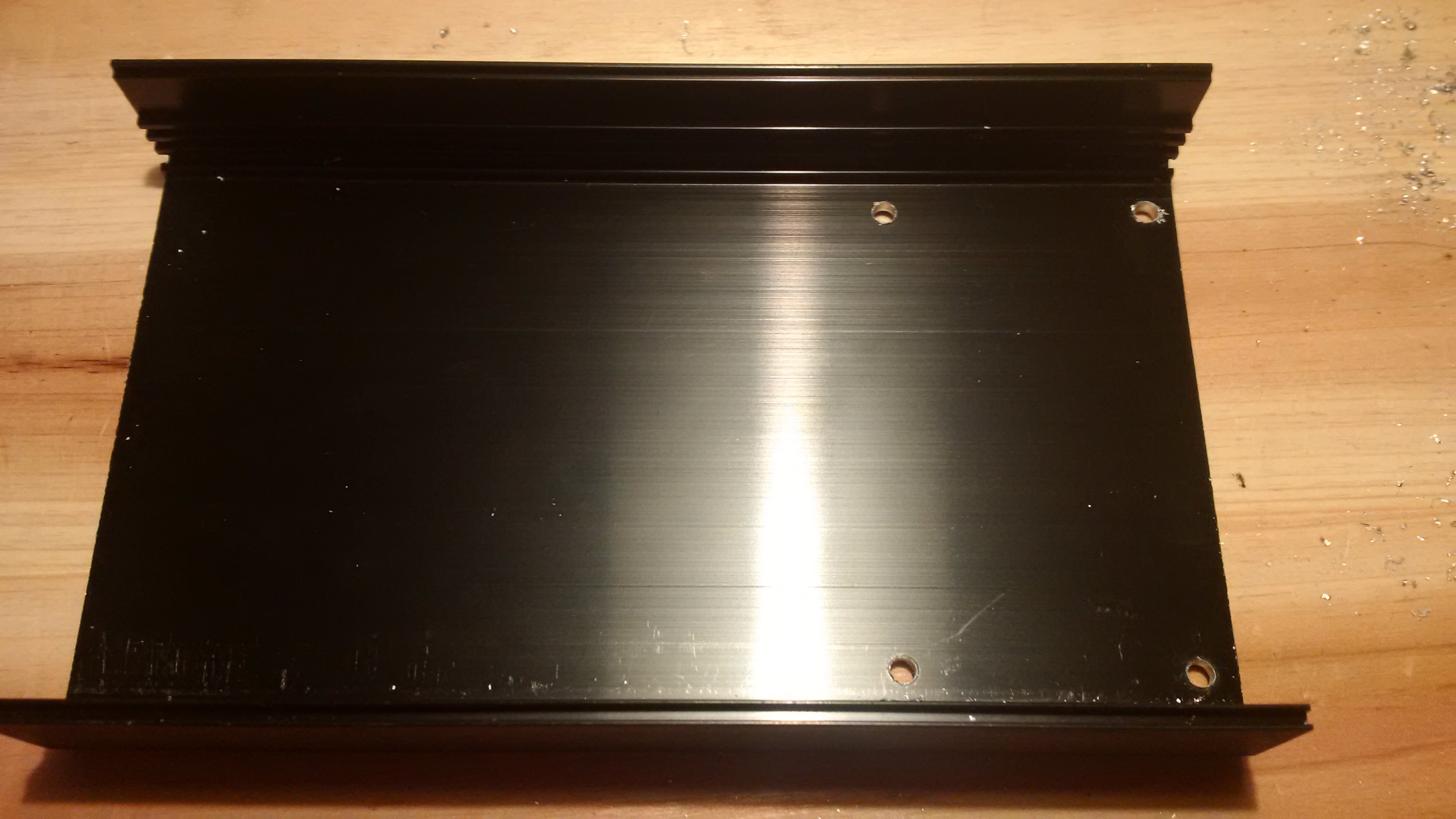
Then I did the same for the phono stage board. Mask the bottom of the case, mark where the holes go and drill:
You can see the result above, eight nice holes in my aluminum box.
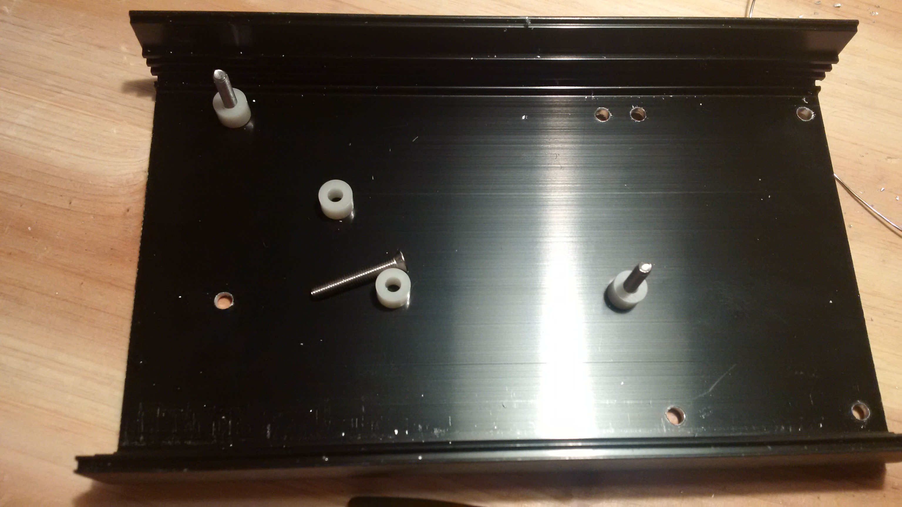
To mount the boards I used size M3 screws and nuts, and 5mm plastic spacers:
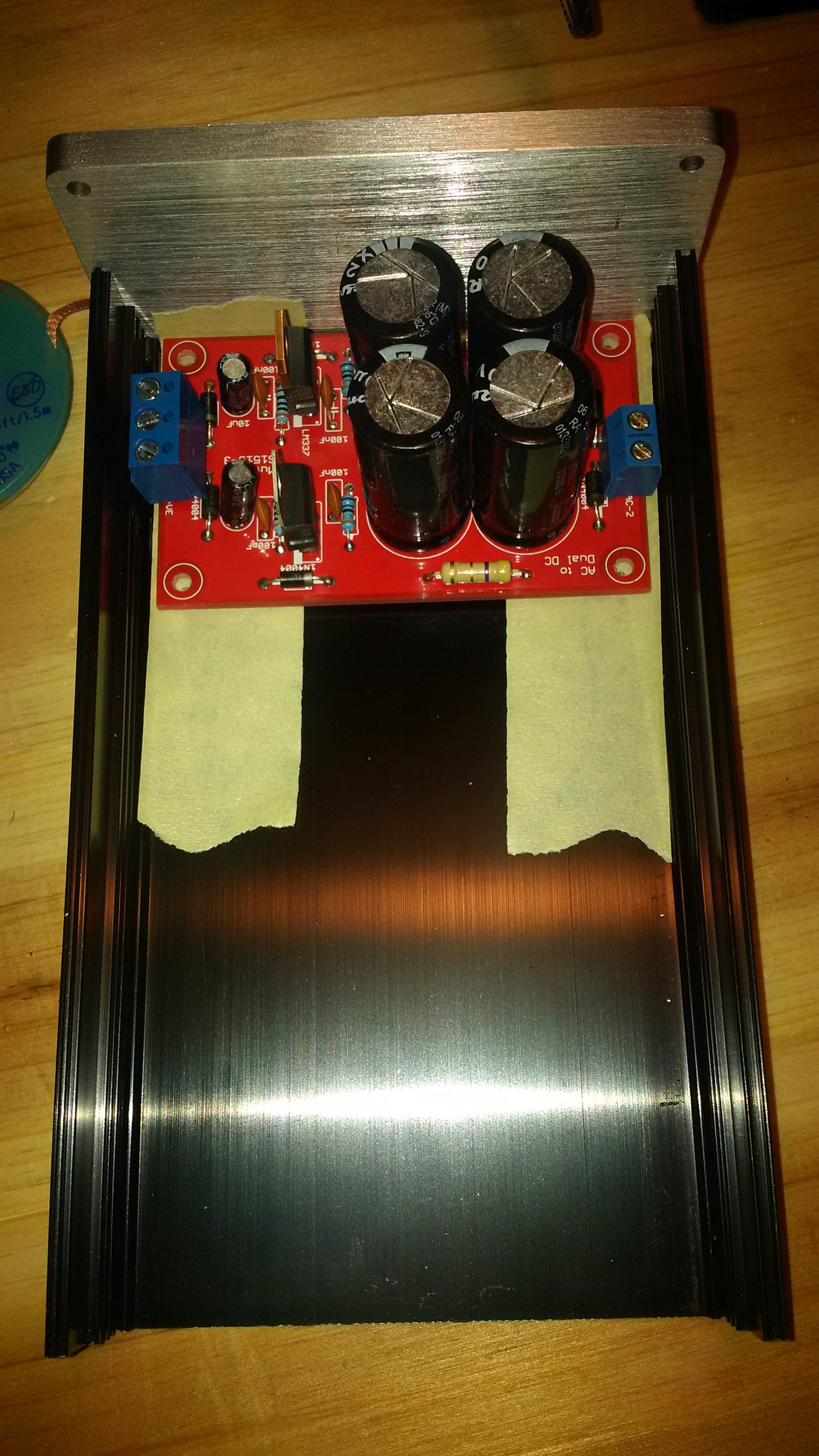
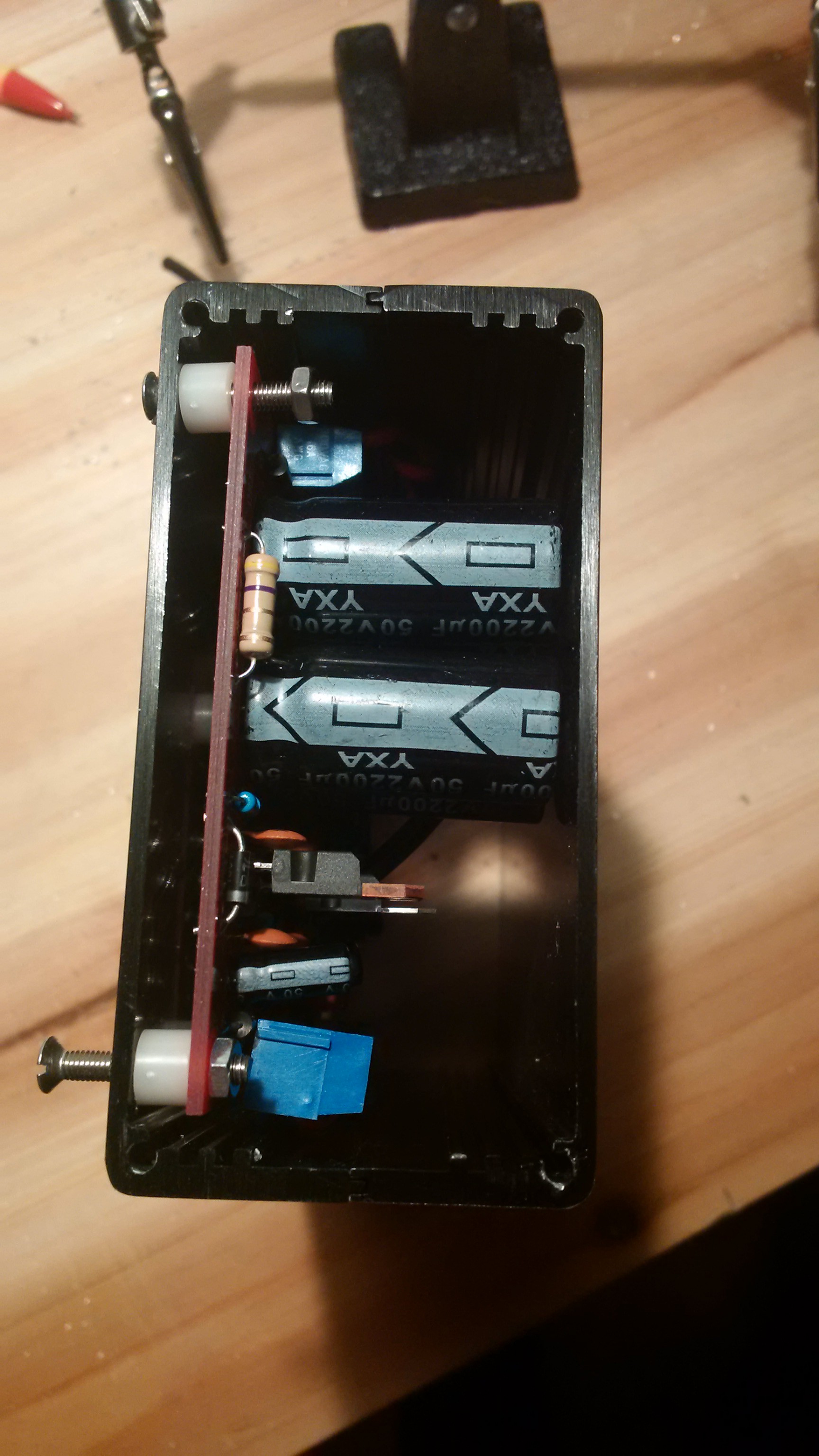
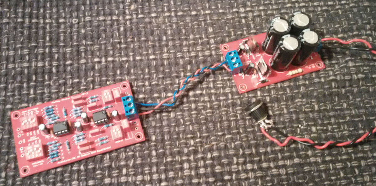
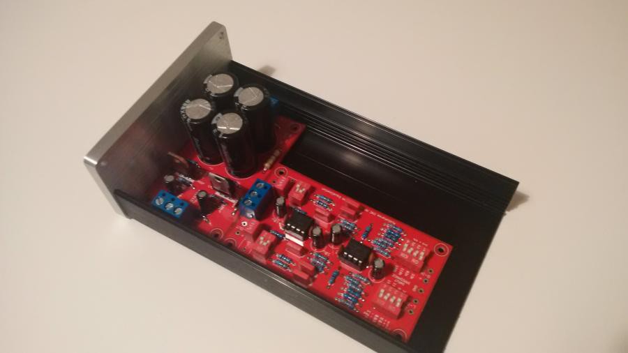
After completing this step, I was anxious to see if there was space for the rather large 2200uF capacitors. It all fit, with a little room to spare:
Time to tighten those screws, and I'm another step closer to a complete phono stage:
(This picture shows the finished project. Technically, I am done. But I'm still going to show how to power the phono stage, and do the audio wiring.)
-
More Gain? Less Gain?
04/01/2015 at 09:37 • 0 commentsThe nice thing about DIY is that you can adapt it to your exact needs. This even goes for the gain on the Muffsy Phono Preamp.
Click this link for more details on the gain stages.
Here's more information on considerations when choosing gain.
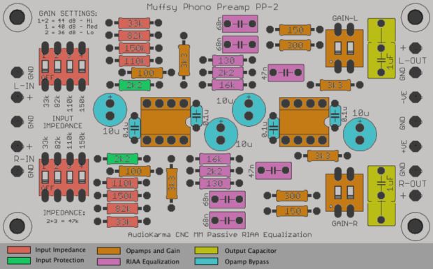
The variable gain in this circuit is set by the switches on the right hand side named "GAIN-L" and "GAIN-R". They choose one of the 150R and 300R or connects them in parallel.
The switches must be set the same for both channels, and these are the standard gain options:
- Switches 1 and 2 set to ON: 44 dB
- Switch 1 set to ON: 40 dB
- Switch 2 set to ON: 36 dB
By changing these two resistors, you can get other gain levels.
This is what you get by replacing them with 120R and 220R:
- Switches 1 and 2 set to ON: 46 dB
- Switch 1 set to ON: 42 dB
- Switch 2 set to ON: 38 dB
If you replace the 150R resistor with a 100R one, you get these gain options:
- Switches 1 and 2 set to ON: 48 dB
- Switch 1 set to ON: 44 dB
- Switch 2 set to ON: 36 dB
Things to note:
- You must always set at least one of the switches to on.
- The last example gives the highest recommended gain, any higher and you may get noticeable noise.
Resources for calculating gain:
- The first gain stage is set to 31 dB
- The RIAA filter has an 18 dB attenuation
- Total gain will be second gain stage + 13 dB
- Non-inverting opamp gain calculator
- Parallel resistor calculator
-
Choosing Gain
04/01/2015 at 08:53 • 0 commentsBy default, the Muffsy Phono Preamp lets you choose between these gain levels:
- 36 dB - 63 times amplification
- 40 dB - 100 times amplification
- 44 dB - 158 times amplification
Which amplification should you actually choose?
The most natural choice would be the gain that gives a level that is closest to your other sources. But like everything, it's not always that simple.
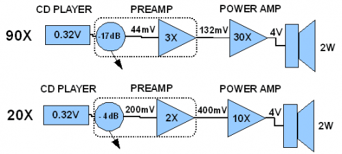
(Picture by Michael Mardis, aka Pano, on http://www.diyaudio.com)
Ideally, you should have gain staging in mind (also known as gain structure or gain distribution).
Having too much gain so you need to bring down the signal level with your volume control or other means of attenuation, means that you will introduce more noise in your audio chain. The Signal to Noise level goes down, sometimes considerably and audibly.
The way to improve your setup is to actively distribute gain between your phono stage, preamplifier and power amplifier to avoid damaging your SNR level.
Michael Mardis, known as Pano on http://www.diyaudio.com has written a very good article on the subject:
Even if you can't change the overall gain in your equipment, it still makes for an informative and useful read. It has prompted me to reduce the gain in my power amp.
-
Building the CNC - Back Panel
03/27/2015 at 21:12 • 0 commentsContinuing on my build, I got the phono stage completed, my PSU and the 0905 enclosure to house everything. The problem is that the back panel of the enclosure has a big hole in it for an IEC connector. That's no good...
I ended up working with plexiglass for the very first time. Let me tell you, that's no walk in the park. Unless the park is full of dragons and crocodiles and other things that makes you very cross indeed.
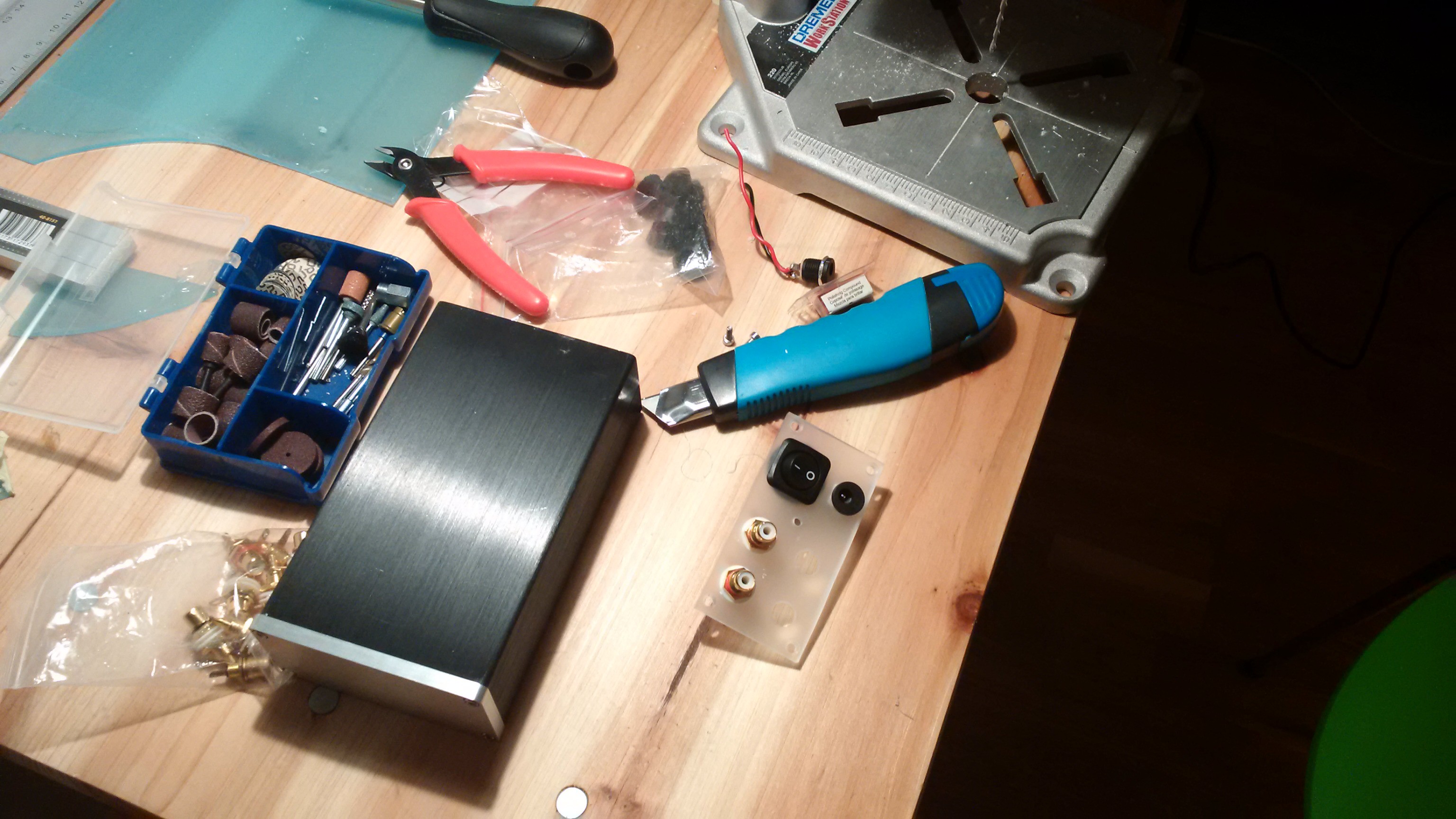
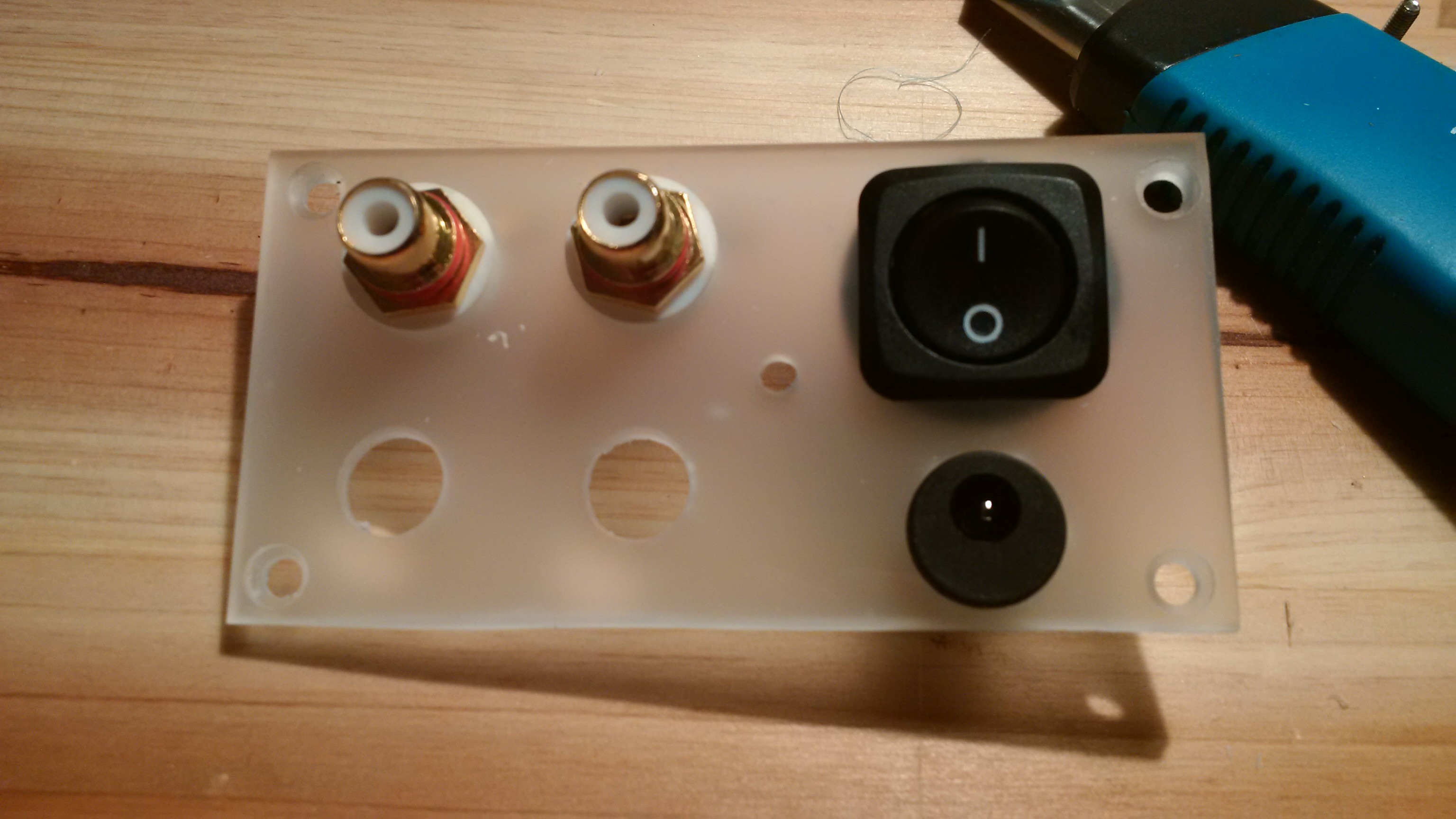
Nonetheless, I think I got the hang of it. Here are a few pictures. This first one shows my desk with a lot of clutter and a piece of plexiglass that has a power button, a 2.1mm power connector and the first two RCA plugs:
Here's a close-up of the back panel at this stage:
As you can see between the RCAs and the power button and connector, there's a hole for the ground screw.
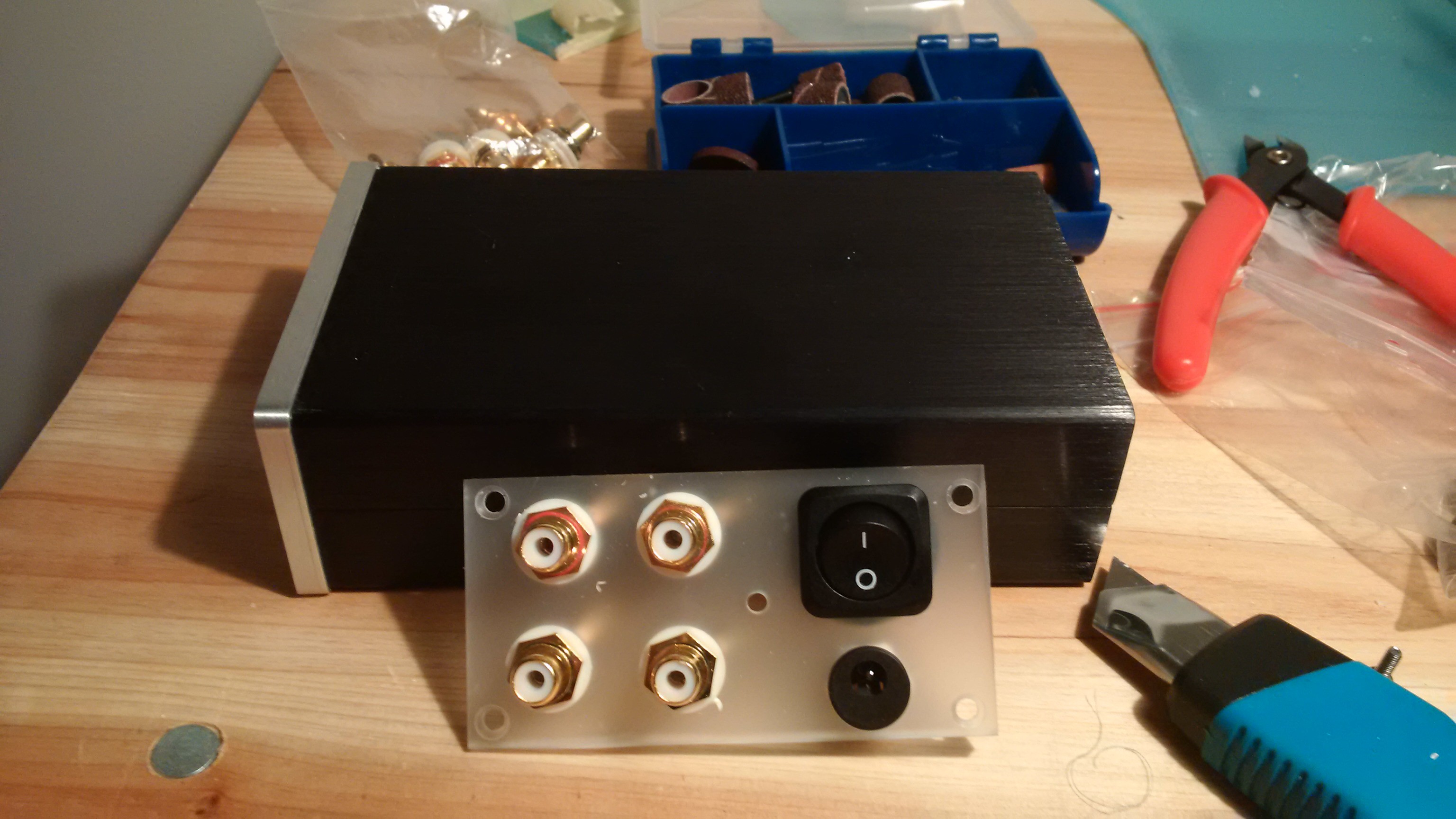
Now, here it is completed (yes, I know, the ground screw is still missing):
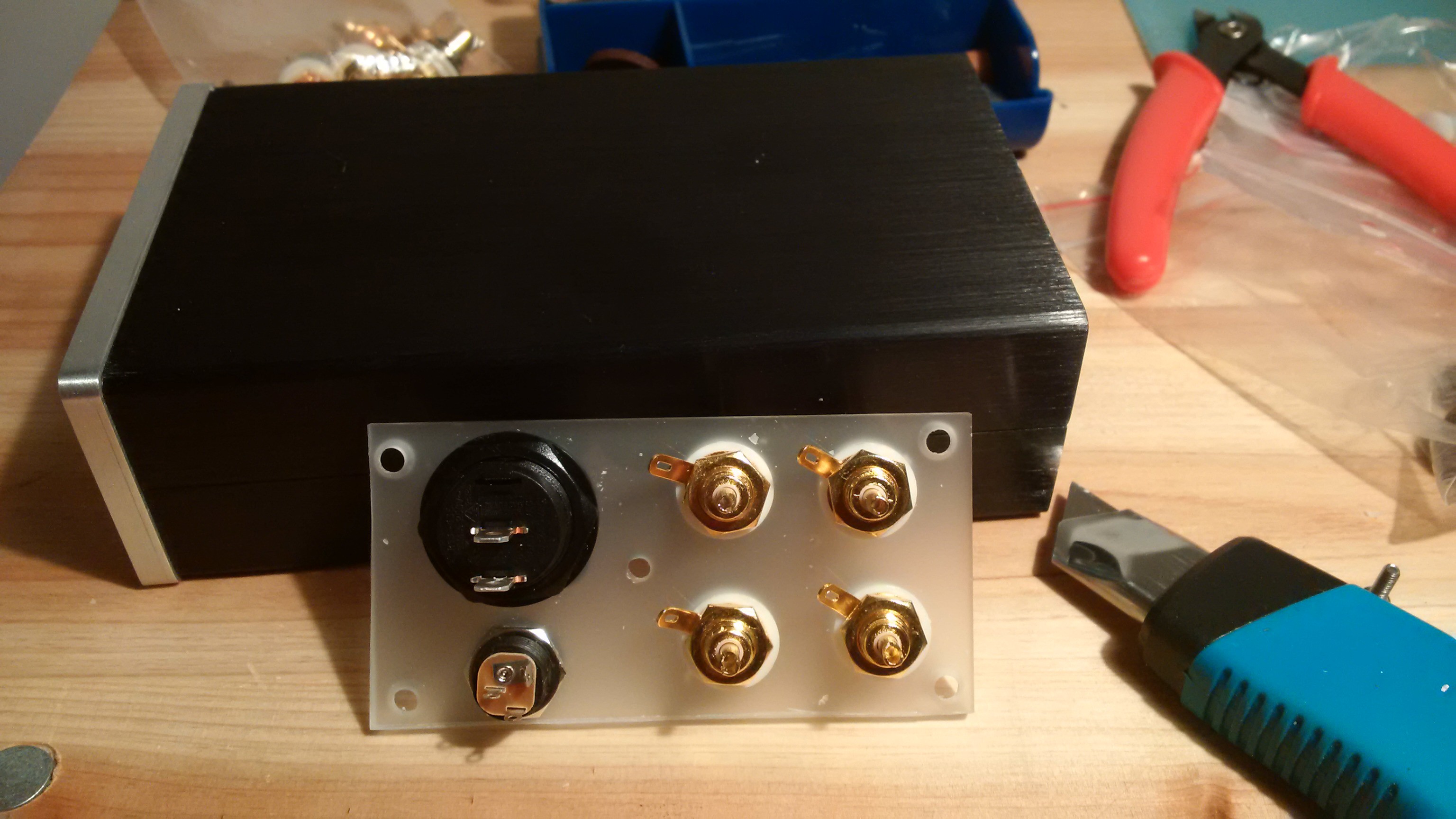
The backside looks like this:
I already noticed a problem, the nuts on both the power button and the power connector are touching the enclosure. I did think the power button looked too big when I bought it... That's DIY for you, I'll glue them to the back panel instead.
Anyhow, that's one step closer to a working phono stage.
If you should wonder about the tidying up afterwards, it was almost as bad as working with plexiglass.
-
Input Impedances - Make them Your Own
03/27/2015 at 14:44 • 0 commentsRest assured, my phono stage build is coming along nicely. There'll be more about that in future log entries. For now, let's play around with the circuit a bit.
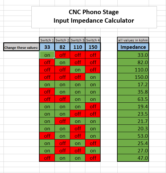
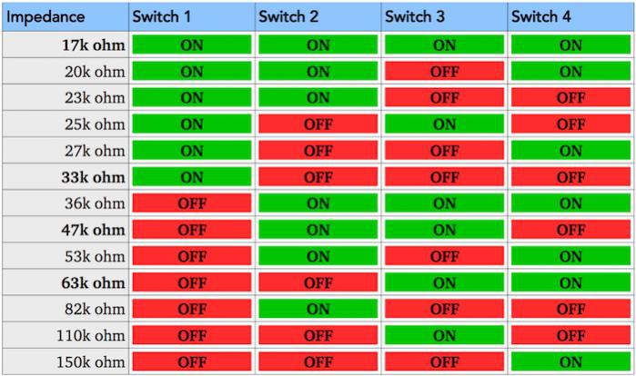
The Muffsy Phono Preamp comes with a set of preselectable input impedances. There is nothing stopping you from changing them, but what to?
To help you decide the best set of resistors, use this Excel impedance calculator. Simply fill in different resistor values and see the impedances change.
NOTE: The industry standard input impedance is 47 kOhm. I would recommend that at least one of your settings matches that, or has a value that's reasonably close to 47 kOhm.
You may notice that there are a few more values in this table (which uses the default Muffsy PP-2 values) than what I have presented earlier. That's because I chose to ignore some of the impedances that are almost equal.
Here they are again, for your reference:
You may also wonder why these values still differ a bit. Well, you see, I did some rounding to make them look nice. Yup, I took that liberty...
-
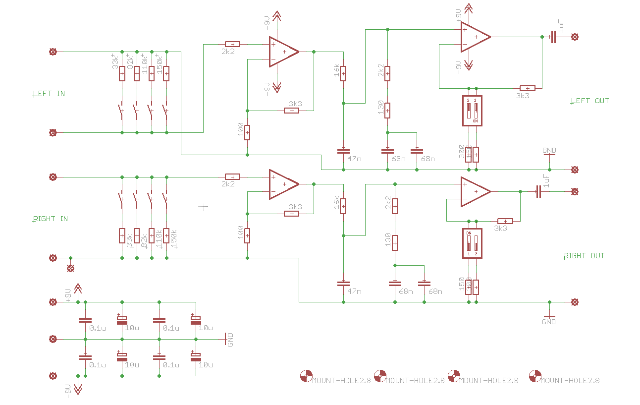
Schematics
03/24/2015 at 23:18 • 0 commentsBelow are the schematics for the Muffsy Phono Preamp PP-2, complete with all component values:
Visit the gallery for a larger version, or use this direct link.
-
Powering the Phono Stage
03/22/2015 at 22:13 • 0 commentsAn Ultra-low Ripple Hifi Power Supply
The power supply has its own project pages:
http://hackaday.io/project/4879-hifi-regulated-dual-power-supply
Opamp based circuits require a dual power supply to have optimal performance. Usually +/- 15 volts.
Getting there usually requires transformers, which hooks up to mains electricity, which is an electrocution hazard first and a fire hazard second. So... What if we could circumvent that by using an ordinary wall-wart?
Well, I built one of those, and it's a perfect match for our little phono stage. :)
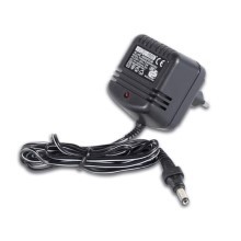
Above is a 15V AC-to-AC adapter, and it hooks up to the PSU which powers the CNC phono stage like this:
I now have the phono stage, an enclosure and a power supply. This brings me much closer to a fully functional phono preamplifier, and I'll keep you up to date on my build.
I could stop here, but there is something else I'd like to share. That's how the PSU performs. You see, I hooked my multimeter to the power output of the supply, to see how much ripple it had. The meter said a nice 2-4 millivolts.
But if you remember from the gain stages project log, there are some bypass capacitors. They prevent opamp oscillation and smooth out the power.
So, I connected the multimeter on the opamp power input pins and measured again. The meter said 0.000 volts. It just won't measure anything below 1 mV.
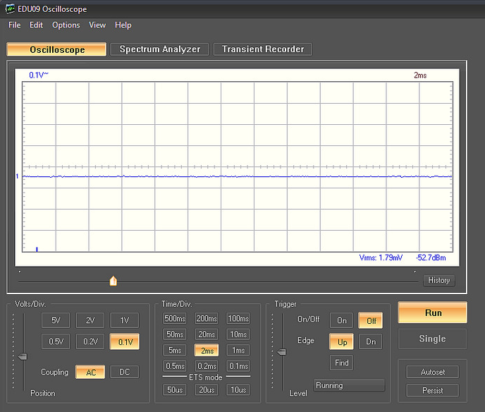
Inspired, I brought out the oscilloscope and measured the PSU output again. It has less than 2 mV of ripple:
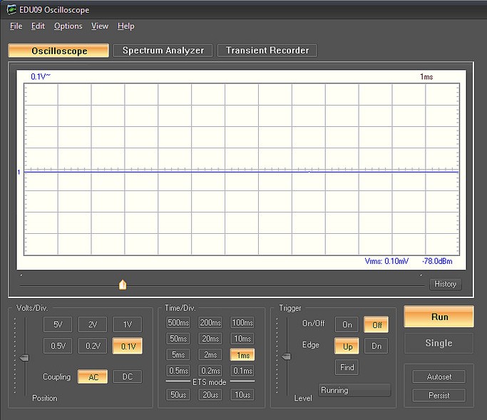
The effect of the opamp bypass capacitors is really good, as the ripple was lowered to a measly 0.1 mV:
To be fair, the scope varied from 0.07 mV up to 0.14 mV. I'd call that low ripple any day, and that this is decidedly a good Sunday to be building a power supply.
-
Finding an Enclosure
03/20/2015 at 13:00 • 0 commentsI found that the 0905 enclosure is big enough to house both the phono stage and my my power supply:
Having populated the PCB is well and good, now it's going to be a self contained and complete phono preamp.
This is what I have in mind:
- Enclosure
- Phono stage
- LM317/337 powered by a 15V single AC wall-wart
- Power connector
- Power button
- Power LED
- Ground screw
- Stereo RCA inputs and outputs
For this to come together, I need to test the PSU and have a look at the output on the scope before I continue.
Using a wall-wart saves me the potential hazard of using mains power. I have designed the PSU to have low ripple, but that (as I said) remains to be seen. Even if there is some ripple, the onboard opamp bypass capacitors will smooth out the power even further.
This is not overly critical anyway. The PSU I'm using in another phono stage has several mV of ripple and the preamp is dead quiet and performs exceptionally well.