Close
0%
0%

Simple Electronic Compass

A simple electronic compass intended to be small, low power, and relatively low cost for everyday carry.

lucLuc
Similar projects worth following
A small, portable electronic compass

Overview:

I was inspired to build my own electronic compass after seeing the compass demo on the STM32F3 Discovery board and there have been a few times recently when I was navigating a new city or area, and had wished that I had brought a compass with me. This project will be to develop an electronic compass similar to the demo on the discovery board, but much more portable than lugging around a full development board and 5V supply. I'm hoping that setting up this project will motivate me to document my progress all the way through, and hopefully there are some other people who would be interested in building one of their own (provided I actually get this done in a reasonable amount of time).

  • Log 05: Proof of Concept Prototype

    Luc05/28/2015 at 00:34 0 comments

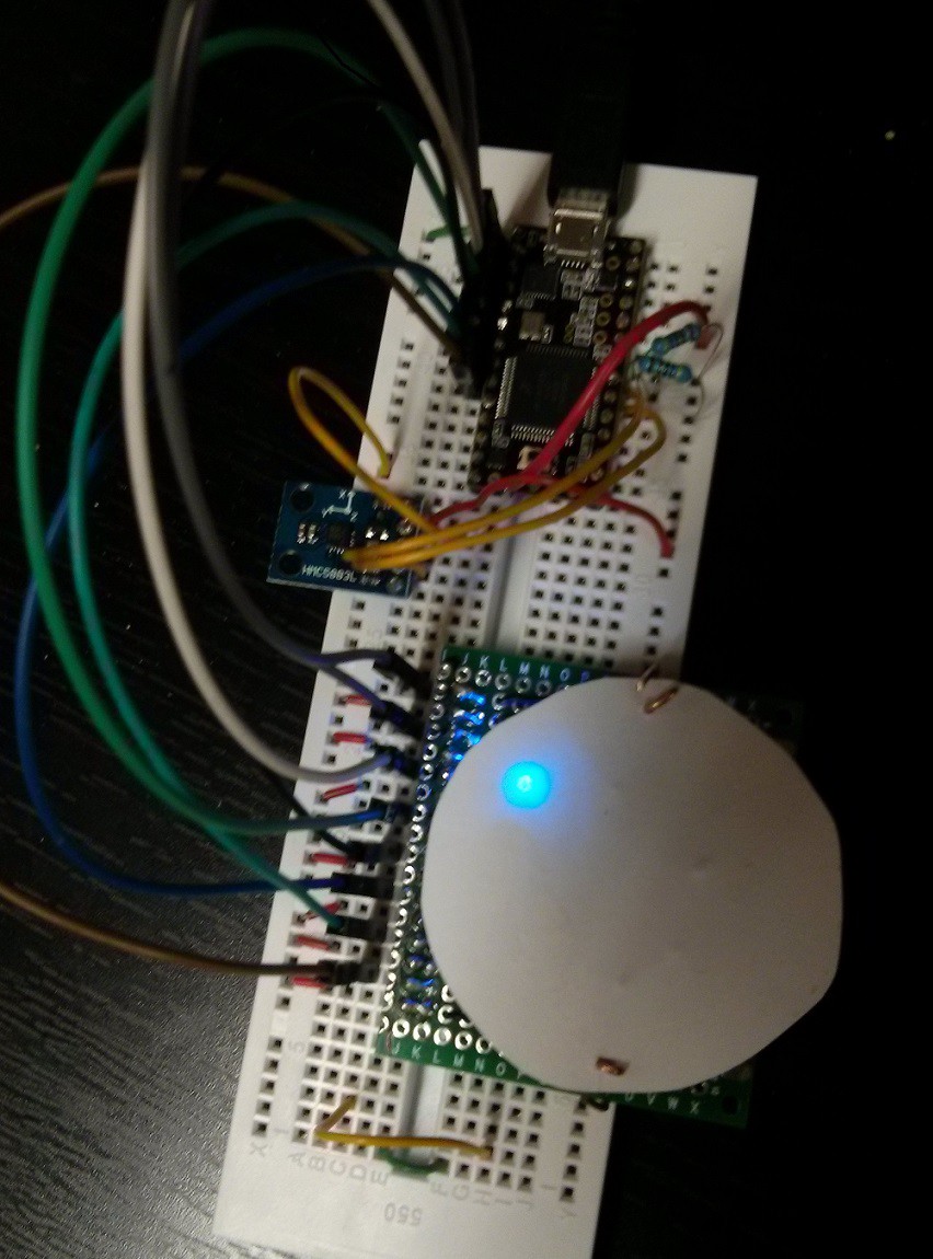
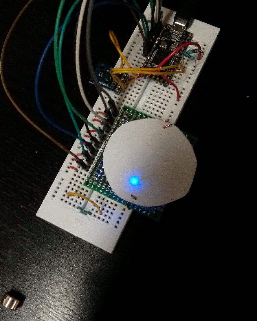
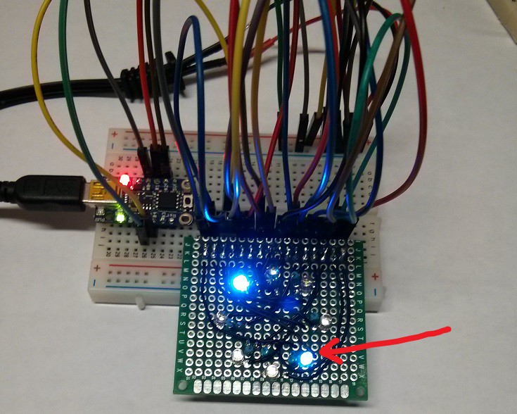
    Finally got to writing some sample code for the compass, based off of the Adafruit Arduino library (git repo here), and I've gotten the whole setup working. Now I just have to fix it up, streamline it, and then test it on an attiny. I've included some images of it working below. The first image shows the measured magnetic north and the second image shows the magnet I used for testing in the bottom left corner. Once I figure out the components/footprints I'll be using (mcu package, battery holder, etc), I plan on doing the board layout next.

  • Log 04: Sensor and Display Changes

    Luc04/23/2015 at 23:14 0 comments

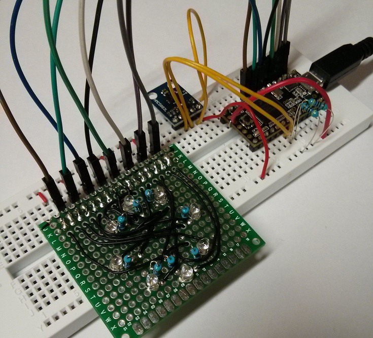
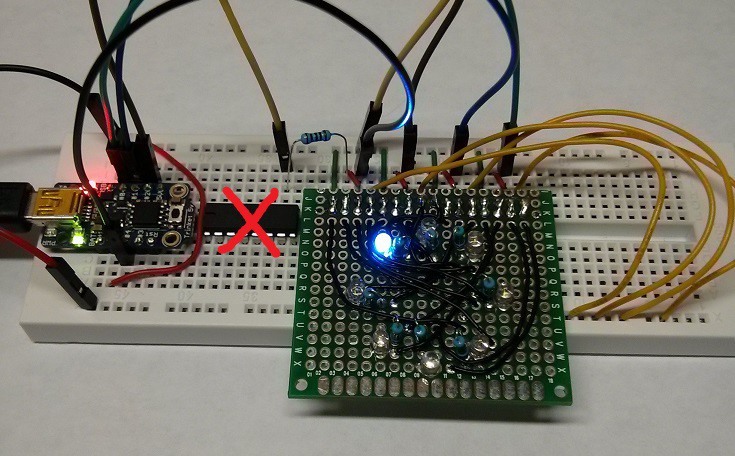
    Quick update: After a grueling month of waiting for the cheap ebay sensors to arrive, they are finally here! I've hooked one up and I'm in the process of writing some test code to get everything working on the breadboard. I neglected to get the sensor breakout board with level shifters on the I2C lines, so I've switched over to a Teensy for the prototyping since it's one of the few 3.3V boards I have. This also lets me drive each of the LEDs independently from their own pins, which simplifies things. I'm still planning on porting over to an AVR chip for the final board. However, I think I'll stick with 1 LED per pin, so I won't be using an attiny85 like I had originally planned. A picture of the current setup is included below, and hopefully I'll have it all working soon.

  • Log 03: LED Display

    Luc03/23/2015 at 02:17 0 comments

    For the visual interface of the compass, I am planning on using 8 LEDs laid out in a ring. Since I'm planning on using an ATTiny85 at this point, I would only have 4 pins for driving the LEDs (with 2 already used for the I2C connection to the magnetic field sensor). Thus I did some experimenting with different ways to drive the LEDs without any extra components.

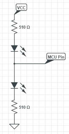
    I tried out charlieplexing first, but for only turning on a single LED at a time, the flicker was quite noticeable. Thus I tried out a different method, with only 2 LEDs / pin, in the following configuration:

    So I soldered up a ring of LEDs and hooked everything up to a 5V trinket (from Adafruit) that I had laying around. However, I ended up having to use 3.3V for Vcc on the LEDs, since the resistors were not large enough to prevent both LEDs from turning on with 5V as Vcc. On the final PCB, I'll make sure that I choose high enough resistor values, but since this was just meant as a demo, the work around will do. Once I had everything hooked up, I noticed there was another issue: one of the LEDs would remain on even when coded to be turned off.

    I made sure all the connections were good on the breadboard and the PCB, and that none of the wires were loose/shorting, but the same LED kept giving me issues. I tried switching the pins around, and apparently pins 3 and 4 of the trinket I am using have issues with Hi-Z mode (input mode), since none of the other pins had the same problem on any of the other LEDs. I'm not sure if there is just some capacitive coupling on pins 3/4 from somewhere else on the board or if there was some interference (although turning off the fluorescent lights didn't help at all), but I ended up just putting a 1 kOhm pull down resistor on pin 4 of the microcontroller (show below).

    Doing so got rid of the problem, so I may have to do something similar on the final board, or even use a shift register or decoder chip for driving the LEDs. I would like to avoid doing that, as extra chips would require more power, take up more space, and increase the final cost. Hopefully getting rid of the reset pin (using it as I/O) won't cause any problems (fingers crossed that I can get the firmware right on the first go) but we'll see what happens.

  • Log 02: Starting Up

    Luc03/19/2015 at 22:48 0 comments

    I managed to find some HMC5883L modules on ebay for <$1 US shipped, so I picked some up and now I just have to wait for them to arrive from overseas. If the tests go well, then I'm hoping to be able to desolder the components from one of the boards to use on the final PCB, which is why I ordered a few. For the brains of the device, I'm considering using an ATTiny85, as its the one of the smallest microcontrollers I have on hand and it has just enough pins to cover the I2C to the sensor and LEDs (2 LEDs/pin). I plan on testing the concept at some point, but ultimately I'm waiting on the sensors to arrive at this point.

    EDIT: I also did a quick mockup of what it may look like (using Eagle and SketchUp) just to get rid of the blank image for the project.

  • Log 01: Brainstorming

    Luc03/18/2015 at 01:44 0 comments

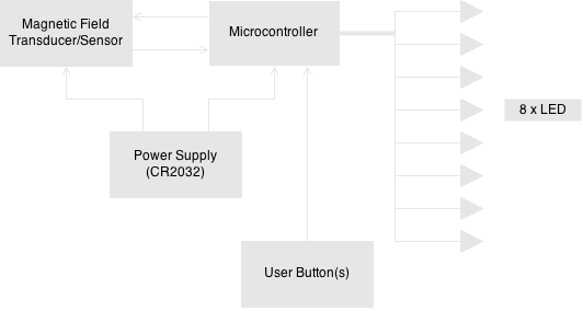
    As an initial step in this project, here is some of my brainstorming: I'm aiming to power the entire device from a single CR2032 coin cell battery, it will have 8 LEDs to show the direction of north, and have at least 1 push button for user interaction. For functionality, I'm thinking that the user will just press and hold the button to display the direction of north on the LEDs and then the system will be disconnected from power when not in use. From some initial searches, the MAG3110 from Freescale seems like it may work, and I will probably end up using a small AVR chip for the microcontroller, as I don't have a PIC programmer at the moment. It's a fairly simple system, but I've included a block diagram of the system as it currently stands, and I doubt it will change too much over the course of the project.

    System Block Diagram:


View all 5 project logs

Enjoy this project?

Share

Discussions

alpha_ninja wrote 12/07/2015 at 01:18 point

Just a friendly reminder to please upload your design documents by 23:59 UTC on Dec 8, 2015 to be in the running for #The Square Inch Project!

  Are you sure? yes | no

alpha_ninja wrote 12/02/2015 at 00:43 point

This is your one-week reminder to upload design documents: https://hackaday.io/project/7813-the-square-inch-project/log/28566-design-deadline

  Are you sure? yes | no

Duane Degn wrote 03/18/2015 at 03:24 point

I'm not sure if you've seen the HCM5883L sensor or not but they work really well IMO. There are sellers on ebay who will sell the sensor on a small PCB for about $2.50 (shipped). You might want to consider using these really inexpensive sensors.

  Are you sure? yes | no

Luc wrote 03/18/2015 at 04:25 point

I actually just stumbled across the HCM5883L today and there is a semi-local store close by which has little boards like you described. I'll have to pick one up and check it out. Thanks for the suggestion!

  Are you sure? yes | no

Similar Projects

Does this project spark your interest?

Become a member to follow this project and never miss any updates