TTN
TTN-
Implementation: Y axis
04/17/2015 at 09:19 • 2 commentsOk, so I'm basically going for an Prusa i3 like machine that is close to 100% printed. I would like to avoid using linear rods or bearings, as good rods and bearings aren't cheap.
In a worst case scenario, if my printed rails fail I could always fall back to linear rods but I'd really like to avoid it if at all possible.
In theory, if I can get a printable axis that has 0.8mm error in linearity in it, and it can position to an accuracy of 0.6mm then I should be able to have the machine self replicate.
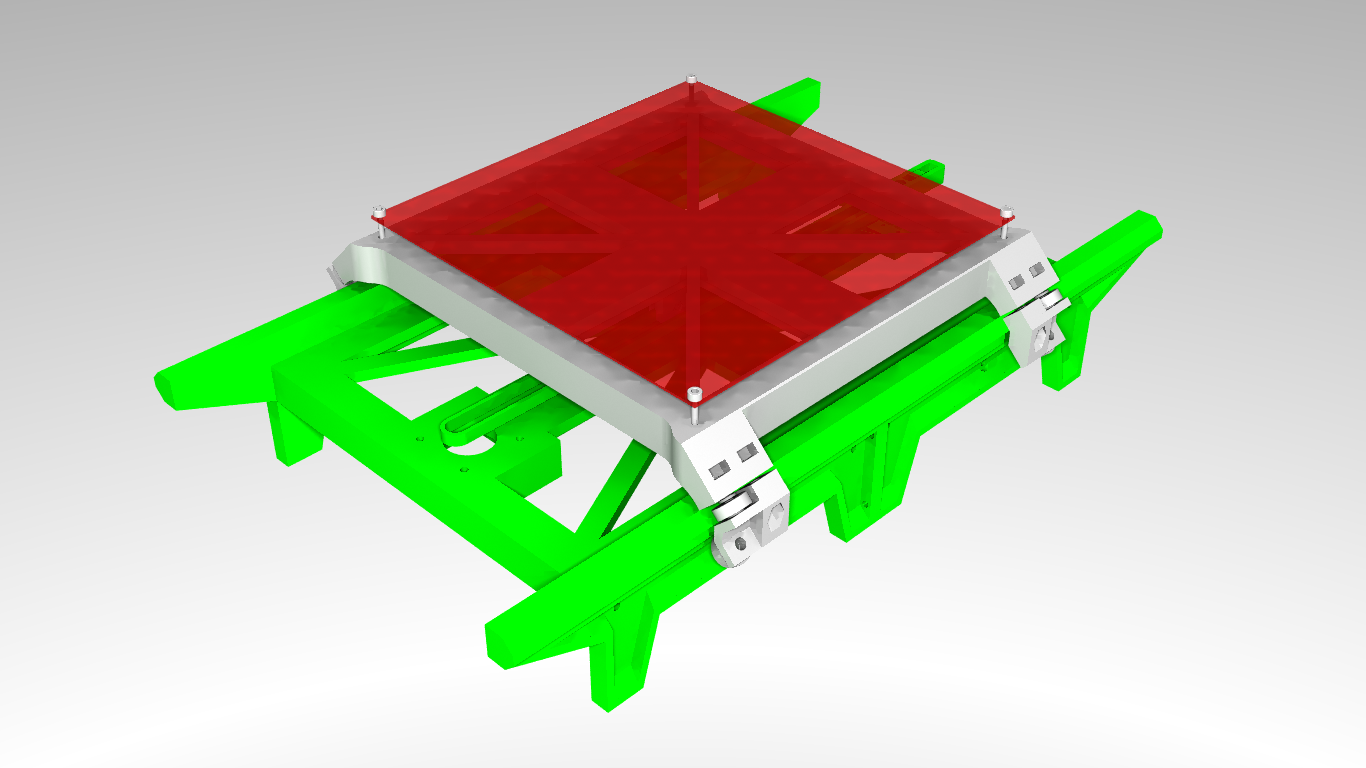
I've been doing some designing and here's what I have at the moment:
![]() I'm using FreeCad 0.15 and povray for rendering. Both are free, open source and are available here and here.
I'm using FreeCad 0.15 and povray for rendering. Both are free, open source and are available here and here.Implementation:
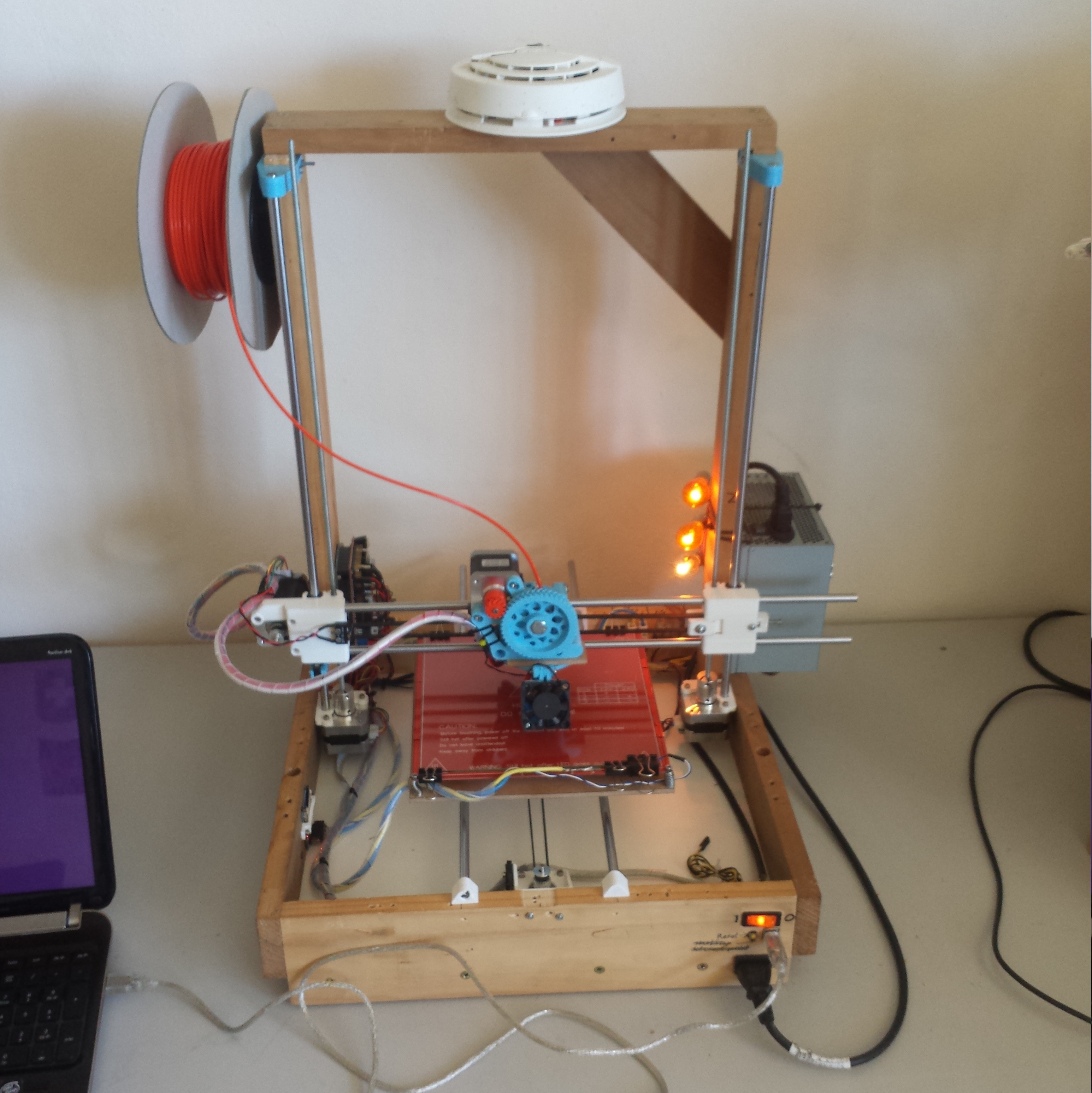
I needed a machine to print on. Since the Icepick Delta wasn't printing accurately enough for my purposes I rebuilt my repstrap into a proper reprap (this was some weeks back) and ordered parts for Reprap Nuemann. Ever so much better than the my original repstrap:
![]()
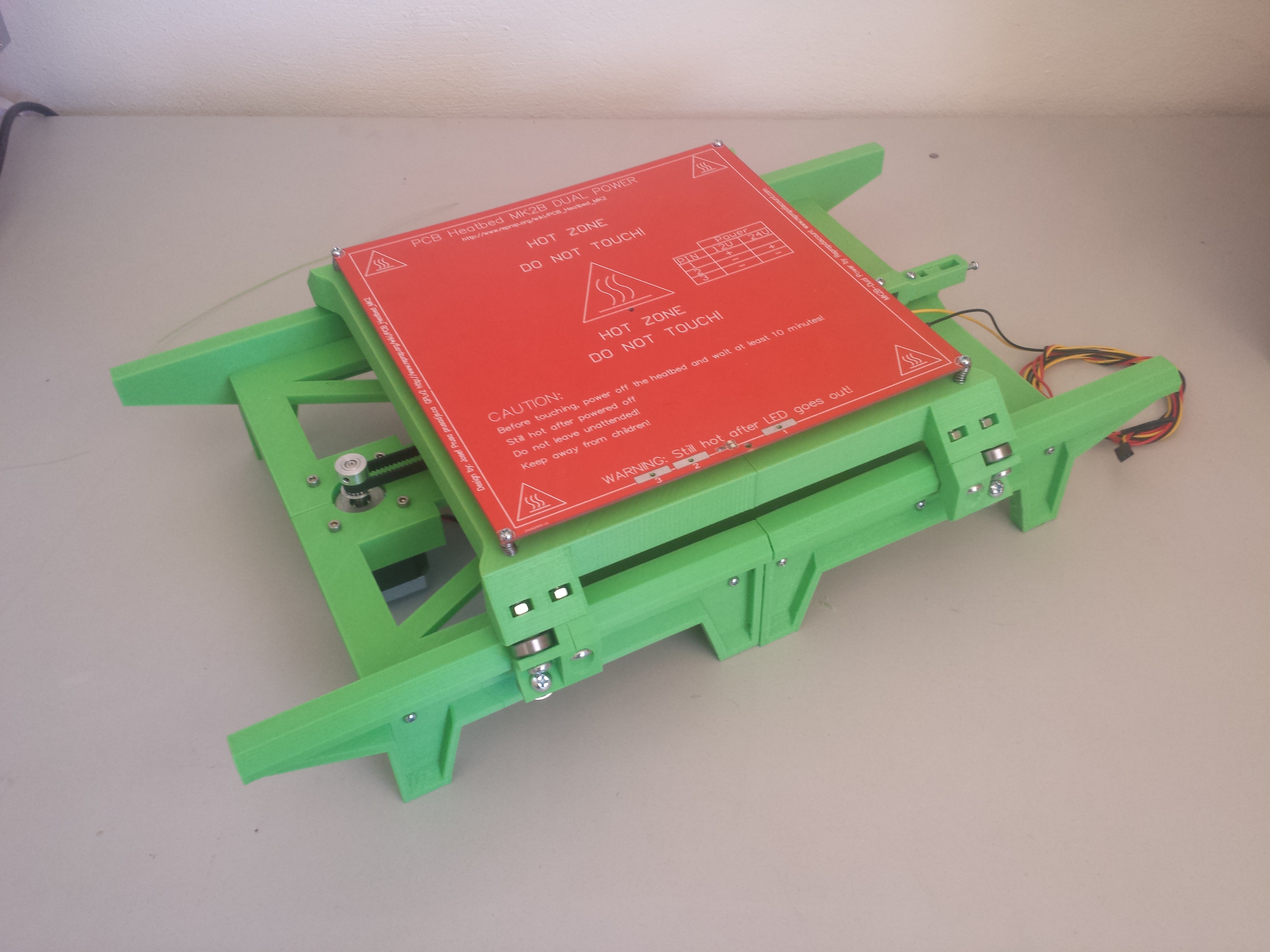
And printed:
![]()
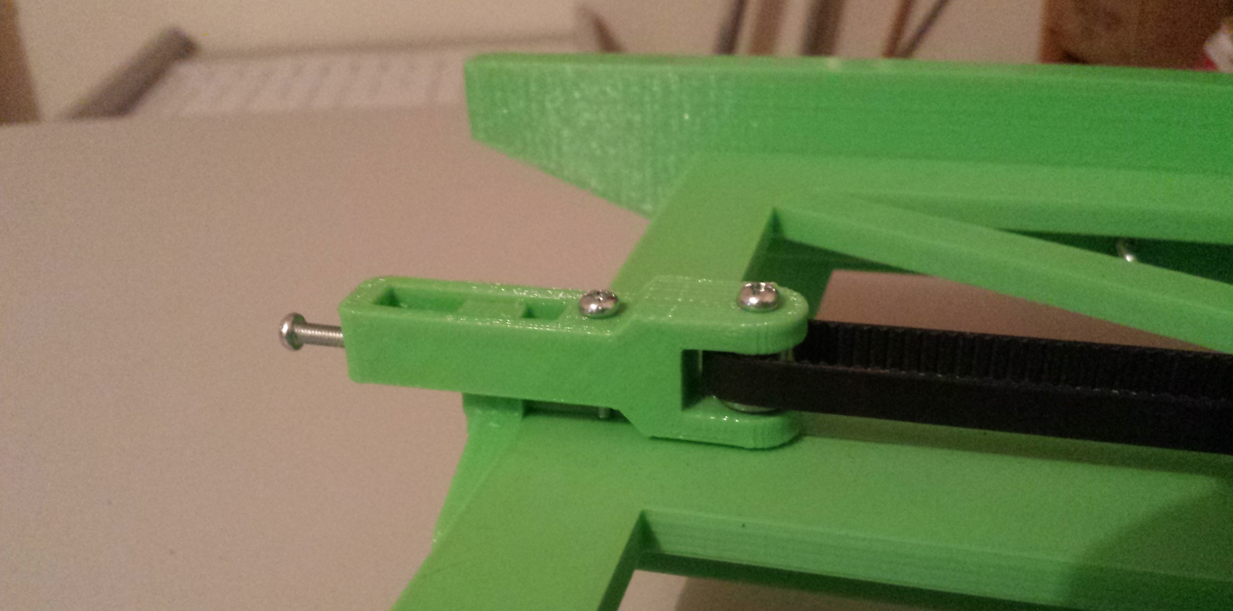
Features a robust belt clamp and adjustable tensioner:
![]()
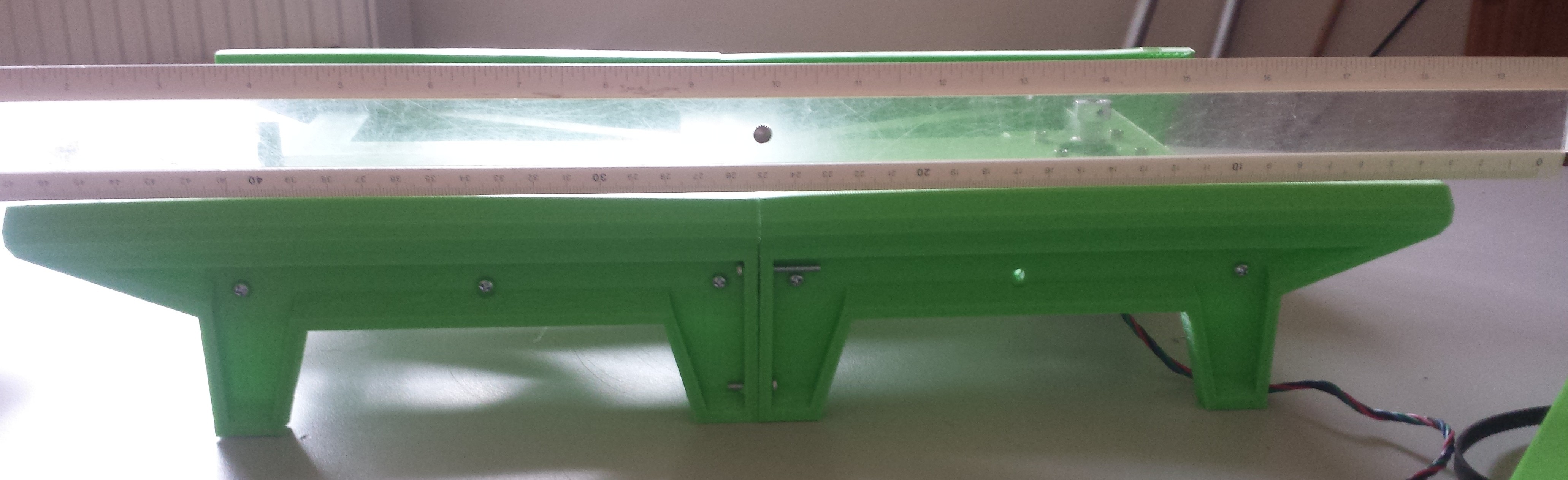
It works nicely, though, there is an issue: the rail is printed with the top face down. When the part is removed from the build platform it warps. With each rail that I printed I attempted to fix the problem by adjusting my heated bed temperature, less fan, very good first layer adhesion to no avail. End result is that the carriage motion isn't linear and that the rollers have slop near the ends.
![]()
In the next iteration I'll redo the rails so that the face of the rail facing the camera is position upward on the print bed and is bolted to the frame. this way, if, when warp occurs, it will be straightened with help of the frame and not affect the linearity of the motion of the carriage, since the opposing side also had the same warp, but opposing. That is, if the frame hasn't already pulled it all straight.
I'll leave it as it is right now, and get to work on the Z and X axis.
-
Introduction..
04/12/2015 at 10:03 • 0 commentsHere I'll try to explain the beginins of the project, a bit of background of where I'm coming from, the idea, and where I'm trying to go with this project.
As a student, building a Reprap is a cost and time intensive undertaking. I find the concept of a self replicating very interesting. Not having much money to spare led to my interest in highly printable Repraps as a means of reducing cost by printing many parts of the motion system. I was very tempted to build a GUS Simpson and was also looking at delta printers of which a large cost is the linear bearings. I didn't like how the GUS Simpson uses two special bearings. What about building a traditional delta style printer?
Searching on the Internet I found that there have been attempts at creating a traditional delta printer (e.g, RappiDelta, PolyBot), but they were either not well documented, or had low resolution, or were otherwise incomplete (I couldn't find functional firmware), and so I started my last project, the Icepick Delta.
The Icepick Delta has been a success to some extent. It did not require a linear motion system, and therefor was cheaper to build. Some of the issues are as outlined below:
- Calibration is very difficult. Measuring an arm, and entering it in the firmware incorrectly by 0.5 mm will be a quiet a problem.
- The arms and end effector sockets have to be spaced exactly 120 degrees from one another.
- The end-stop distances are critical, there are three to calibrate. If one of these is calibrated incorrectly, parts are made dimensionally inaccurate, e.g. warped, wider as it gets taller, or other weird nonlinear transformations.
- Low repeatability, (banding in prints)
- It cannot self replicate: After days of calibration and fiddling it was printing dimensionally correctly apart from everything being 4% too short in the z-axis.
- The Arduino Mega with a custom version of Marlin firmware could only calculate 40 delta segments per second.
All in all it makes for a very cool looking, low cost minimalistic printer in terms of hardware usage, but it is very difficult to build and not suitable for a beginner. Lessons learned here will help with the Reprap Neumann project for sure.
I came to the conclusion that the GUS Simpson is a very impressive piece of engineering and is simply much better implementation of a highly printable delta printer. The GUS Simpson is practically an inverted delta which removes the need for large frame like the IcePick Delta uses.
Still the problem remains: How can a Reprap be made, so that it can create its own motion system, and still maintain dimensional accuracy when replicating?
I spent a lot of time looking at other designs, trying to come up with an original solution. Some are rather beautiful and elegant pieces of engineering. In my opinion notably: the GUS Simpson, Reprap Morgan and Wally. I eventually came to the conclusion that there are no such Reprap's as of now that can print its own motion system while remaining dimensionally accurate or easy to calibrate as it replicates from generation to generation.
An example would be I had an Icepick Delta, a Reprap Morgan or a Reprap Wally printer and the pulley radius has a slight error in the pulley radius, the next generation that is printed will now have more than the original error in the radius of the new pulley. As the generations are printed this error will increase exponentially. It is the same with the GUS Simpson's arm joints, the Wally's pulleys and the Morgan's pulleys.
Reprap Neumann aims to tackle this core problem by using a very simple design. The problem on the afore mentioned printers that when there is an error, it is magnified. As explained before, the radius of the printer arms are larger than the radius of that pulley that was being used. To achieve a demagnification of error size, the radius of the point of rotation must be larger than the radius of rotation of the print bed. Although I do not think this is practical with the afore mentioned printers, I think I have found a way to achieve this.
The idea is to build printer that uses linear motion with an Y axis as a base on the table, a Z axis that consists of two vertical rails and an X axis that runs in between the two vertical Z axis rails. The rails and guides would be printed. This way by placing the rolling points further from the build platform, any movements will be demagnified, because the radius from the center of the bed to the guide is greater than the radius of the center of the bed to the edges of the printbed.
Advantages:
- Easy to calibrate; by using standard pulleys and GT2 belts the only thing that will need to be calibrated is the extruder steps per millimeter. No dimensional print accuracy critical endstops.
- Highly printable
- Low on vitamins
- Easy to assemble (hopefully). Using nuts and screws to assemble should be straightforward using a diagram and instructions.
- Can self replicate (in theory, will need to do testing to confirm)
Disadvantages:
- Highly printable: needs lots of printed parts
- Takes a long time to print
- Assembly time may be slightly longer due to more parts, maybe offset by ease of calibration
To be continued..
If you have any questions or if what I'm trying to explain is unclear go ahead and ask and I'll do my best to explain :)
Reprap Neumann
An easy to build, open source self replicating 3D printer with a rock bottom bill of materials that maintains accuracy when reproducing
 I'm using FreeCad 0.15 and povray for rendering. Both are free, open source and are available