-
1Step 1
The complexity in the project was not the hardware - although it was a learning experience with the ESP-07 as to what to pull up or down etc.
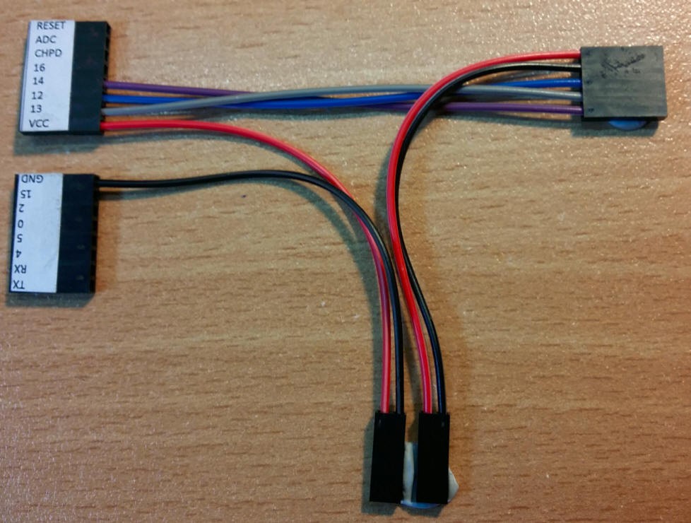
Assemble the programming wiring loom
ESP-07 Pinout (Connector 1 LHS)
- RESET - Pullup to VCC using a resistor - Push button shorts to GND to reset the device
- ADC
- CH_PD - Pullup to VCC using a resistor
- GPIO 16
- GPIO 14 - Connect to DATA on the TM1638 unit
- GPIO 12 - Connect to CLOCK on the TM1638 unit
- GPIO 13 - Connect to STROBE on the TM1638 unit
- VCC - Connect to VCC 3.3v
ESP-07 Pinout (Connector 2 RHS)
- TXD - Connect to RXD on the FTDI chip
- RXD - Connect to TXD on the FTDI chip
- GPIO4
- GPIO5
- GPIO0 - Push Button connects to GND to start program mode
- GPIO2
- GPIO15
- GND - Connect to GND
There are many example circuits out there, search via google.
My programming loom looks like this:

-
2Step 2
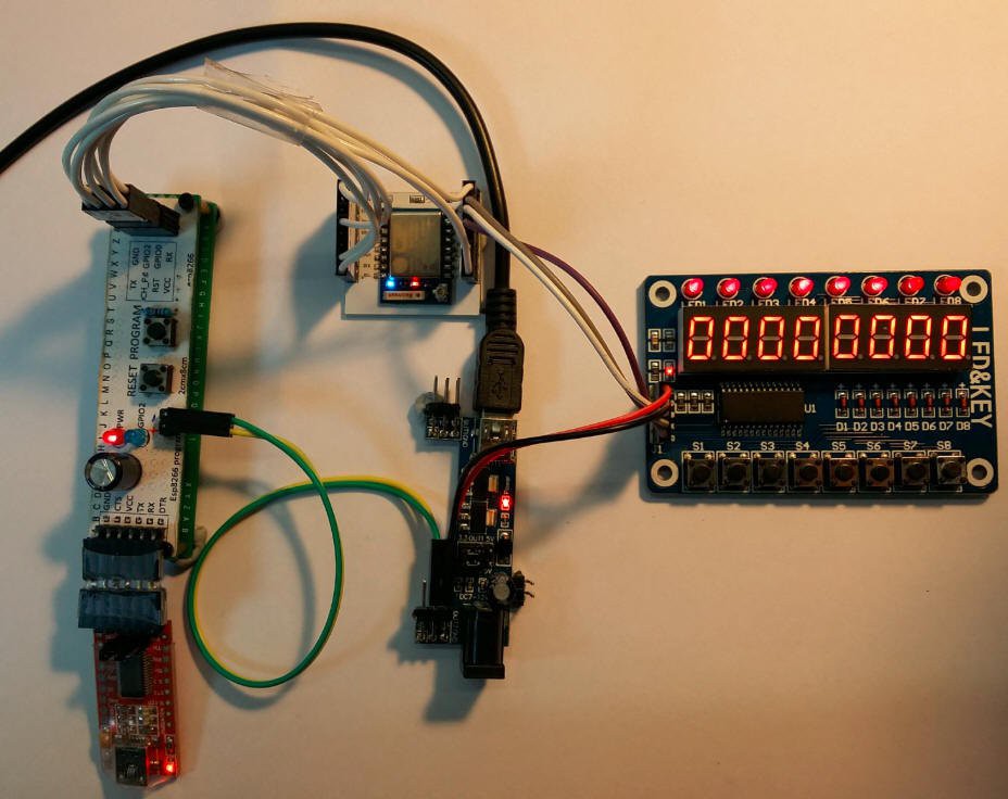
Assemble the run time wiring loom
Once you have programmed and tested the setup then you can simplify the setup with a run time loom. this removes the FTDI and program connections and is much simpler than the programming loom. The two connectors on the left connect to the ESP breakout pins. The top right hand connector connects to the TM1638 display module. The two connectors at the bottom go to the power supply.
TM 1638 Display Pinout
- VCC
- GND
- STB
- CLK
- DIO
-
3Step 3
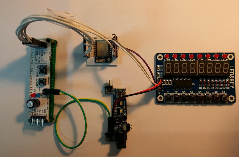
Connect it all up to start testing - The programming loom is shown here:
-
4Step 4
Create the TM1638 Driver
Information Sources
- Data sheet - TM1638
- elcheapo Logic analyzer from Ebay - This was a lifesaver and I could not have got this working without it!
- Various other examples for the Arduino code including http://www.limpkin.fr/index.php?post/2014/12/07/First-Steps-with-the-ESP8266-03-Development-Board
- ESP8266 Pin List Spreadsheet
- ESP8266 Register spreadsheet
- ESP8266 Nurdspace WIKI page
This took quite a bit of messing around. The data sheets for the TM1638 are not very easy to decipher - but actually do make sense when you look back...
The approach I took was very simple bit banging - The ESP8266 is capable of SPI etc but since the interface here is quite specific to the TM1638 and I Really wanted to get this working - I did not try to use the native ESP8266 functions for this.
The code consists of the user_main.c and a separate tm1638.c and tm1638.h library.
TM1638 Library
The tm1638 library includes these main functions:
Initialize the output pins that we will use, called at boot time from user_main.c
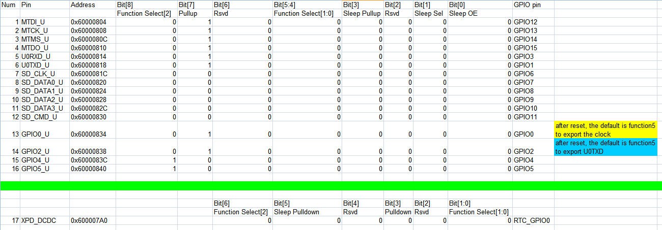
void tm1638Init()
{
   gpio_init(); // Initialize the GPIO subsystem.
   PIN_FUNC_SELECT(PERIPHS_IO_MUX_MTDI_U, FUNC_GPIO14);
   PIN_FUNC_SELECT(PERIPHS_IO_MUX_MTCK_U, FUNC_GPIO13);
   PIN_FUNC_SELECT(PERIPHS_IO_MUX_MTMS_U, FUNC_GPIO12);
   Set14_0; // DATA
   Set12_1; // CLOCK
   Set13_1; // STROBE
   os_printf("TM1638: Init Complete /n/r");
}
The one trick I learnt earlier on (after 4 hours trial and error) was how the PIN_FUNC_SELECT function works and the values to use for the parameters. The first is the internal pin functional name. Each pin has an internal function name, so whilst I'm using pin 14 as a GPIO port, it's internal functional name is PERIPHS_IO_MUX_MTDI_U. So to setup any pin you need to know it's functional name.
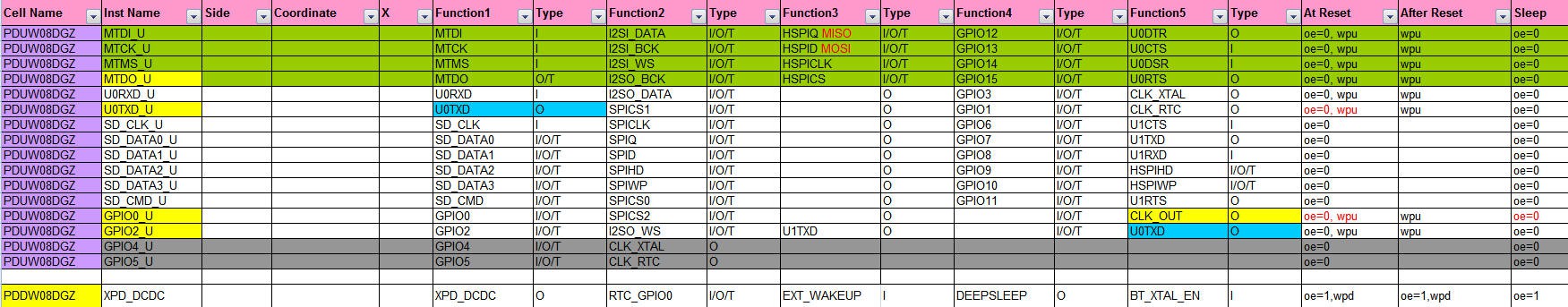
The second parameter sets the mode. Internally FUNC_GPIO maps to a number - in this case 3 which is the mode to enable the pin for GPIO. The spreadsheet I found contains a full description of this. (but I can't find the link to it, so I've attached the entire spreadsheet.)
Digital Die Pin List:
Registers - This shows the various pin modes that are possible:
Next Create shortcuts to switch the pins on and Off:
// These defines create simple shortcuts to switching IO pins on and off.
#define Set14_1 gpio_output_set(BIT14, 0, BIT14, 0);
#define Set14_0 gpio_output_set(0, BIT14, BIT14, 0);
#define Set13_1 gpio_output_set(BIT13, 0, BIT13, 0);
#define Set13_0 gpio_output_set(0, BIT13, BIT13, 0);
#define Set12_1 gpio_output_set(BIT12, 0, BIT12, 0);
#define Set12_0 gpio_output_set(0, BIT12, BIT12, 0);
Next we need to be able to send command bytes to the TM 1638
void tm1638OutByte( uint8_t data )
{


      SEND_tm1638_stb_pulse();
      #ifdef DEBUG
         os_printf("<");
      #endif


      // Send Data
        if( data & 0x01 ) SEND_tm1638_data_1(); else SEND_tm1638_data_0();
                if( data & 0x02 ) SEND_tm1638_data_1(); else SEND_tm1638_data_0();
        if( data & 0x04 ) SEND_tm1638_data_1(); else SEND_tm1638_data_0();
        if( data & 0x08 ) SEND_tm1638_data_1(); else SEND_tm1638_data_0();
        if( data & 0x10 ) SEND_tm1638_data_1(); else SEND_tm1638_data_0();
        if( data & 0x20 ) SEND_tm1638_data_1(); else SEND_tm1638_data_0();
        if( data & 0x40 ) SEND_tm1638_data_1(); else SEND_tm1638_data_0();
        if( data & 0x80 ) SEND_tm1638_data_1(); else SEND_tm1638_data_0();


       #ifdef DEBUG
         os_printf(">");
      #endif


}
The first step in sending a command byte is to make a high to low transition on the strobe.
Then in some rather clumsy code I send each bit using the following functions:
// SEND_tm1638_data_1 : Set the data line to 1
void SEND_tm1638_data_1()
{

   #ifdef DEBUG
      os_printf("D");
    #endif

   Set14_1;
   // Now send a clock pulse to send the data
   SEND_tm1638_clk_pulse();

}

// SEND_tm1638_data_0 : Set the data line to 0
void SEND_tm1638_data_0()
{
   #ifdef DEBUG
      os_printf("d");
    #endif

   Set14_0
   SEND_tm1638_clk_pulse();

}
Sending data is very simple - just set the data bit to 1 or 0, then send a clock pulse using this funciton:// SEND_tm1638_clk_pulse : Send a pulse down the CLOCK line (pin 13) void SEND_tm1638_clk_pulse() { // Configure a delay counter - All delays calculated using a Logic Analyser uint8_t time = 20; #ifdef DEBUG os_printf("C"); #endif while(time--) { Set13_0; } time = 10; while(time--) { Set13_1; } }The clock pulse is timed using a very simple loop counter - luckily the TM1638 is very slack on timing so it does not matter a great deal. -
5Step 5
To receive button presses via the tm1638 driver:
Couple of interesting points here - Part way through I change an output to an input. I also map the odd button mapping across 4 bytes into a single byte. Teh basic sequence to read from the TM1638 is
- Set strobe LOW
- Send command byte 0x42 to tell the TM1638 to send the button press data back
- Switch the data pin to INPUT
- Clock through 32 bits of data reading the input pin after allowing the clock to stabilise
- Set the Strobe HIGH to terminate the flow
- Return the DATA line to OUTPUT MODE
// Routine to fetch the button presses back as a single byte with each bit representing a // button in order. uint16_t TM1638getButtons(void) { uint16_t keys = 0; uint16_t time = 20; uint16_t i=0; uint16_t pinvalue=0; #ifdef DEBUG os_printf("in: TM1638getButtons"); #endif // Send Command 1 - Which tells the TM1638 to send the button presses over the next set // of clock pulses tm1638OutByte(0x42); // Keep the strobe low SEND_tm1638_stb_0; // The data line was configured as an OUTPUT, now switch to INPUT mode gpio_output_set(0, 0, 0, BIT14); // Set GPIO14 as input // Read all 4 bytes. the TM1638 can handle many buttons, this display unit // only uses 8 buttons, but these are spread over the 32 bits returned for ( i = 0; i < 31; i++ ) { // Set Clock Low time=20; while(time--) { // Wait for stabilisation Set13_0; //13 clock } // Now check the data line high or low pinvalue=GPIO_INPUT_GET(GPIO_ID_PIN(14)); #ifdef DEBUG os_printf("%u",pinvalue); #endif // Read input value on the Data Pin (14) // Buttons are mapped across 4 bytes, at positions // 1,5,9,13,17,21,25,29 Hence the various shift operations if( i == 28 ) keys |= pinvalue << 0; if( i == 20 ) keys |= pinvalue << 1; if( i == 12 ) keys |= pinvalue << 2; if( i == 4 ) keys |= pinvalue << 3; if( i == 24 ) keys |= pinvalue << 4; if( i == 16 ) keys |= pinvalue << 5; if( i == 8 ) keys |= pinvalue << 6; if( i == 0 ) keys |= pinvalue << 7; // Set Clock High time=20; while(time--) { // Wait for stabilisation Set13_1; } } SEND_tm1638_stb_1(); // Reset 13 to be an output again PIN_FUNC_SELECT(PERIPHS_IO_MUX_MTDI_U, FUNC_GPIO14); return keys; } -
6Step 6
Create the ESP8266 user_main.c
This is the main code - whose job is to connect to WIFI and setup an UDP server that listens for UDP packets and dumps them to the TM1638 display as ascii. A timer routing checks for key presses every 500 milisecs and displays a binary representation of the buttons on the display.
I won't explain the UDP part as I found most of this in Limpkins' Blog - First Steps with the ESP8266-03 Development Board
The user_init code is:
//Init function
void ICACHE_FLASH_ATTR user_init()
{
    uart_init(BIT_RATE_57600, BIT_RATE_57600);                          // Init UART @ 57600 bps
    network_init();                                                     // Init network timer


    char ssid[32] = "LightningStrikesTwice";                            // Wifi SSID
    char password[64] = "97379039";                                     // Wifi Password
    //char ssid[32] = "B-LINK-MP01";                                    // Wifi SSID
    //char password[64] = "";                                           // Wifi Password
    struct station_config stationConf;                                  // Station conf struct
    wifi_set_opmode(0x1);                                               // Set station mode
    os_memcpy(&stationConf.ssid, ssid, 32);                             // Set settings
    os_memcpy(&stationConf.password, password, 64);                     // Set settings
    wifi_station_set_config(&stationConf);                              // Set wifi conf

    // Init the driver for the tm1638 - just sets up the io pins
    tm1638Init();

    // Set up a repeating timer that checks for key presses periodically
    os_timer_disarm(&key_timer);
    os_timer_setfn(&key_timer, (os_timer_func_t *)key_check, NULL);
    os_timer_arm(&key_timer, 500, 1);

    //Start os task
    system_os_task(user_procTask, user_procTaskPrio,user_procTaskQueue, user_procTaskQueueLen);
    os_printf("\n\rStartup done\n\r");                                  // Startup done
}
The init code sets up a repeating timer to check for key presses and convert the resultant byte into a binary string for display on the 7 seg displays
// key_check: Poll the keyboard and check for keypresses
// This routine is driven by a timer that operates periodically.
void ICACHE_FLASH_ATTR key_check(void)
{
   uint8_t data;
   char buffer[10]="....";

   // Bring back a 8 bit value representing keypresses.  1 button per BIT
   // This routine also decodes the odd bit vs button mapping of this unit.
   data = TM1638getButtons();

   // Convert the value into a displayable Binary value
   //  0000 0000 - No buttons pressed
   //  0101 1010 - four buttons pressed
   tobinstr(data, 8, buffer);

   os_printf("READ %u\n\r",data);

   // Send the Binary string to the display
   tm1638OutBuffer( buffer, 8);


}
To convert the integer into a binary string I used this function// tobinstr: Integer to Binary // Convert an integer in to a STRING containing the BINARY equivalent. void tobinstr(int value, int bitsCount, char* output) { int i; output[bitsCount] = '\0'; for (i = bitsCount - 1; i >= 0; --i, value >>= 1) { output[i] = (value & 1) + '0'; } }Finally the UDP receive code is triggered whenever a packet is received on port 2222 and does this:
static void ICACHE_FLASH_ATTR udpNetworkRecvCb(void *arg, char *data, unsigned short len)
{
    struct espconn *udpconn=(struct espconn *)arg;

    //  Diagnostic output via the FTDI USB port
    os_printf("UDP RECV [");
    os_printf(data,"%d");
    os_printf("] ");

    // We have received an UDP packet - so let's dump it to the TM1638 LED display as ASCII
    // data.

    // Disable the watchdog timer to prevent reboots during the data send operation
    ets_wdt_disable();
     os_intr_lock();
     tm1638OutBuffer( data, len );
     os_intr_unlock();
    os_printf("\n\r");

}
ESP8266 Driving an ebay TM1638 Button/7seg display
Drive an elcheapo TM1638 display unit using an ESP8266
Discussions
Become a Hackaday.io Member
Create an account to leave a comment. Already have an account? Log In.