-
Component pick and place
02/18/2018 at 11:59 • 0 commentsThe very first PCB I assembled was populated using tweezers but it didn't take long to realise that tweezers are not very efficient for a number of reasons:
- There's not enough space around a component in the tape to get the tips of the tweezers in and pick up the part.
- If the components are densely packed on the board the tweezer tips get in the way of placing them
- Trying to release the component without disturbing it's placement is remarkably hard when you have to move your placement hand to release the component.
I'd watched Mike from Mikeselectricstuff use a piece of tube with a blunt needle to pick and place parts with the vacuum supplied by sucking on the end of the tube. Although somewhat awkward to use, this setup was enough to convince me that it was worth investing more into a proper vacuum pickup pen of some sort.
![]()
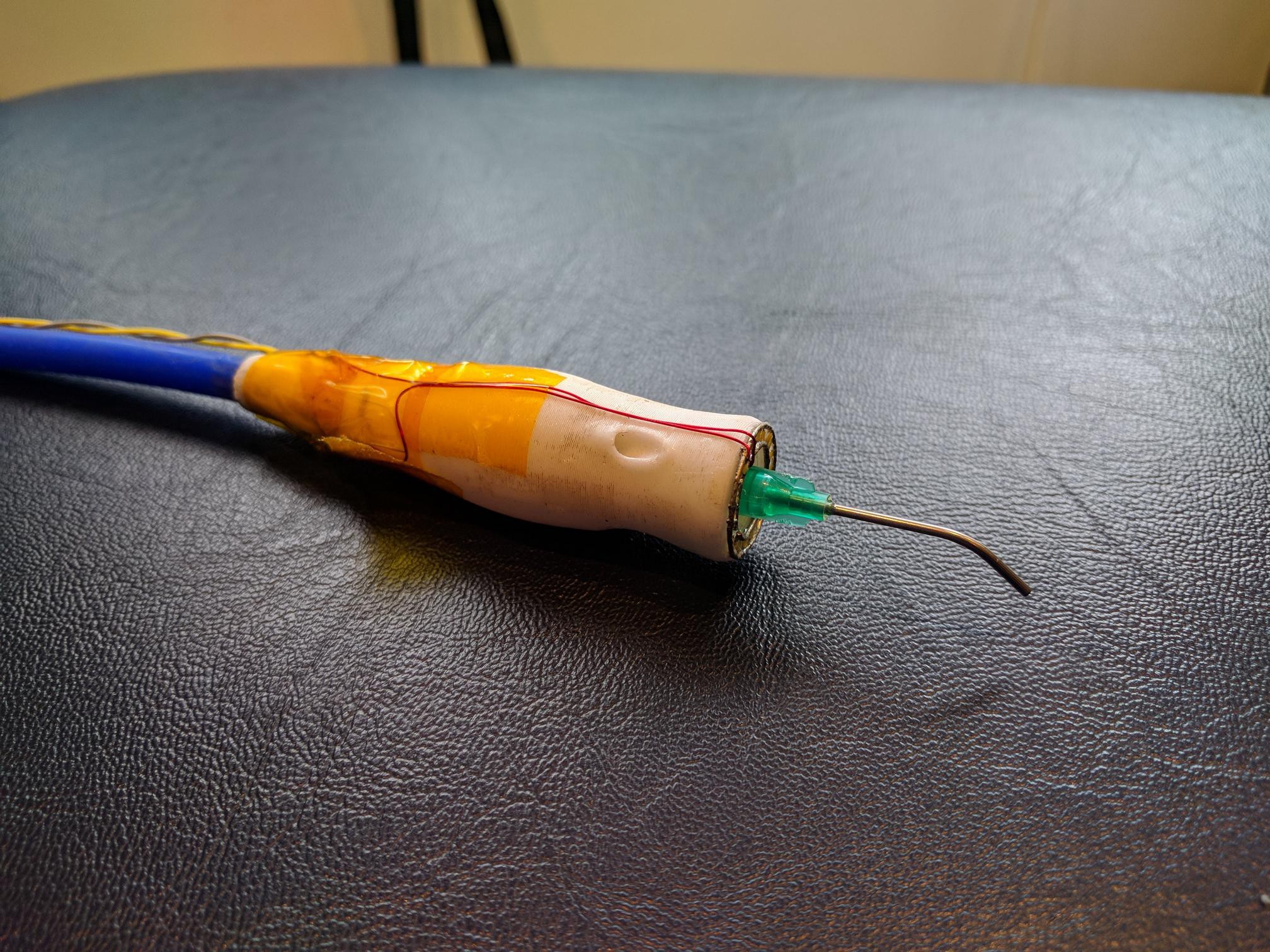
My first vacuum pick up pen looked like this although to begin with it didn't have the light ring. This is still a very simple setup, essentially this is a tube with a hose at one end and a needle at the other with a hole allowing you to control the amount of vacuum. The tube runs to a small, dc, vacuum pump that runs continuously. To pick a part up you would cover the hole with your finger creating a vacuum at the tip of the needle. One you have placed the part, removing your finger from the hole allows air in breaking the vacuum at the needle and releasing the part. This was a massive improvement over the tube-in-the-mouth setup but there were a couple of drawbacks:
- Once again, releasing the part meant moving the placing hand, this could easily disturb the part as it was being released.
- That thick blue silicone tube was too stiff and could make it difficult to place parts very accurately.
One advantage of this system is that by partially covering the hole you could regulate the amount of vacuum at the needle. With practice it was possible to have just the right amount of vacuum to pick up parts, place them and have them release from the needle once they were stuck in the solder paste without any movement of the finger.
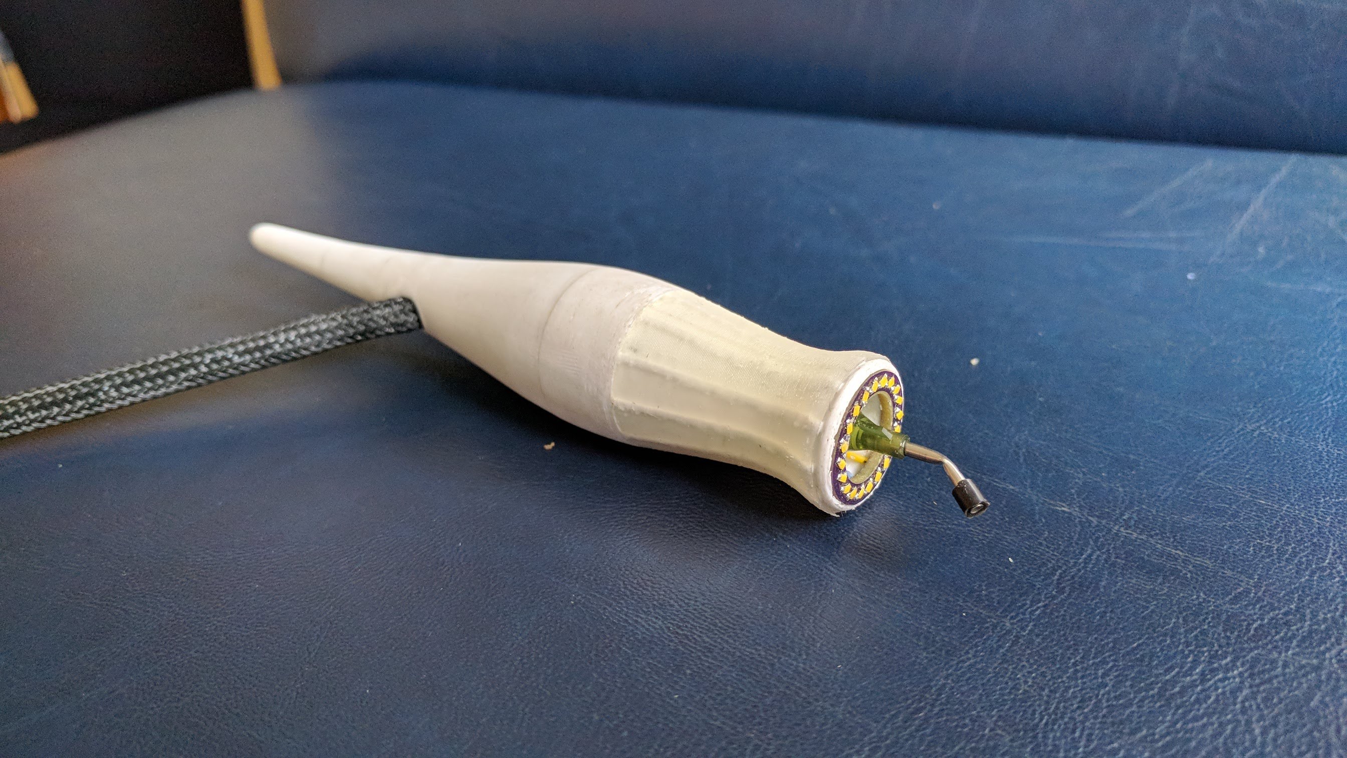
I probably assembled over 100 PCBs with this setup, I added the light ring which was a huge improvement. I find that 0603 parts are really pretty easy to handle provided you have enough, and even, light. The LED ring provides light in exactly the right place and without any shadows.
![]()
After a few months of using this system I wanted to try and improve it again. This iteration has a solenoid valve integrated into the pen body. The solenoid is controlled by a foot switch so finally I can place a part and release it without needing to move the placing hand at all. The pen is also larger in diameter and has a moulded silicone cushion to make it more comfortable to use for longer periods of time. The umbilical contains the wires for the solenoid and the LED ring which is now a proper PCB, having the umbilical enter half way up the pen reduces the amount it affects positioning the pen. I have various sizes of needle for the pen but typically I only use two, the one shown in the picture for larger parts and chips and a longer but thinner one for passives.![]()
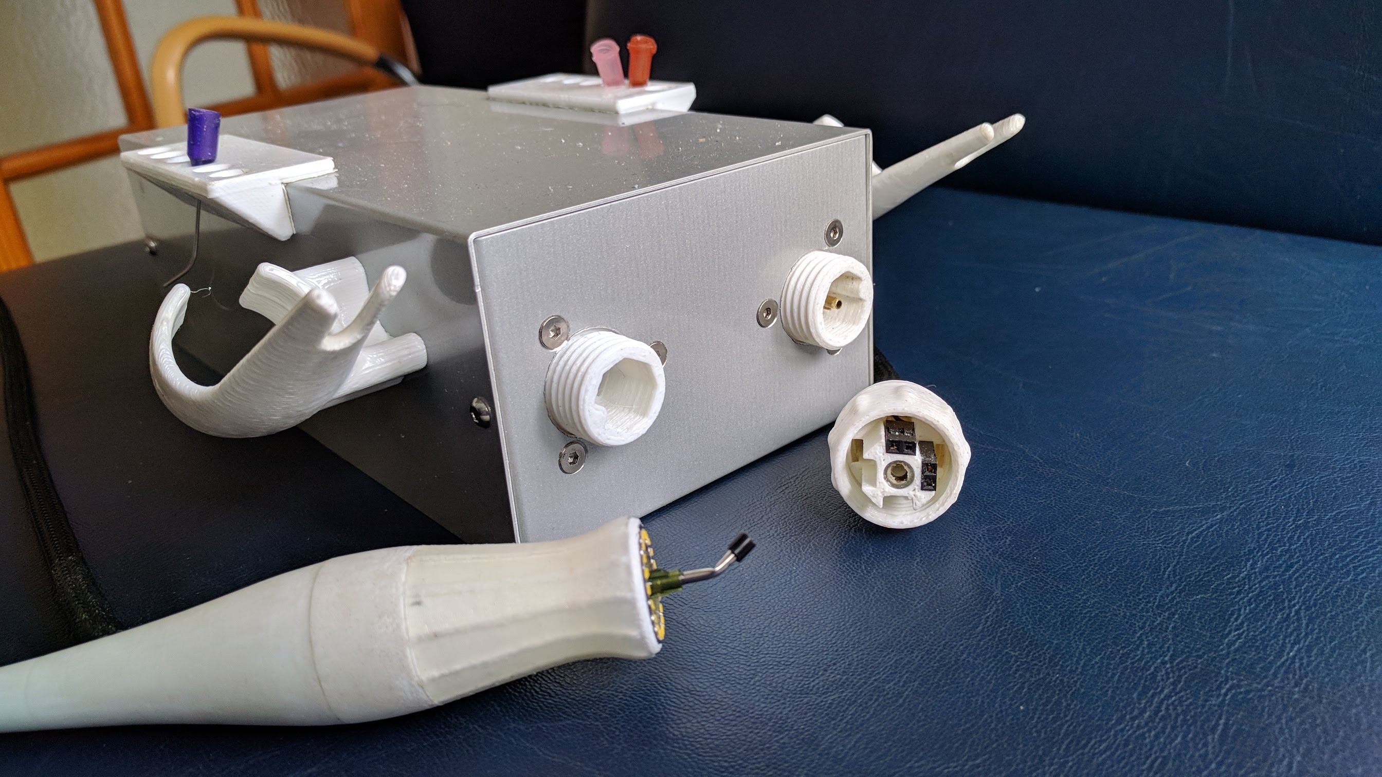
The vacuum pump is housed in this box which also houses a PWM speed controller and connectors for the pen (on the right) and the foot switch (on the left) as well as holders for the pen and spare needles.
-
SMD Tape and feeders
02/13/2018 at 10:30 • 0 commentsI used the flat tape feeder shown in the last log for a couple of months, it was an order of magnitude better than sticking tape to a piece of wood but still it had plenty of drawbacks.
- Longer component tapes still flapped about all over the place.
- Spent tape would encroach on the work area
- Batch sizes kept getting bigger and I would again run out of certain components.
- Ergonomically, assembling components flat on a bench is pretty uncomfortable.
About this time it was becoming obvious that there was a reasonable market for our product and it would be worthwhile investing some time and money to streamline the production process as much as possible.
![]()
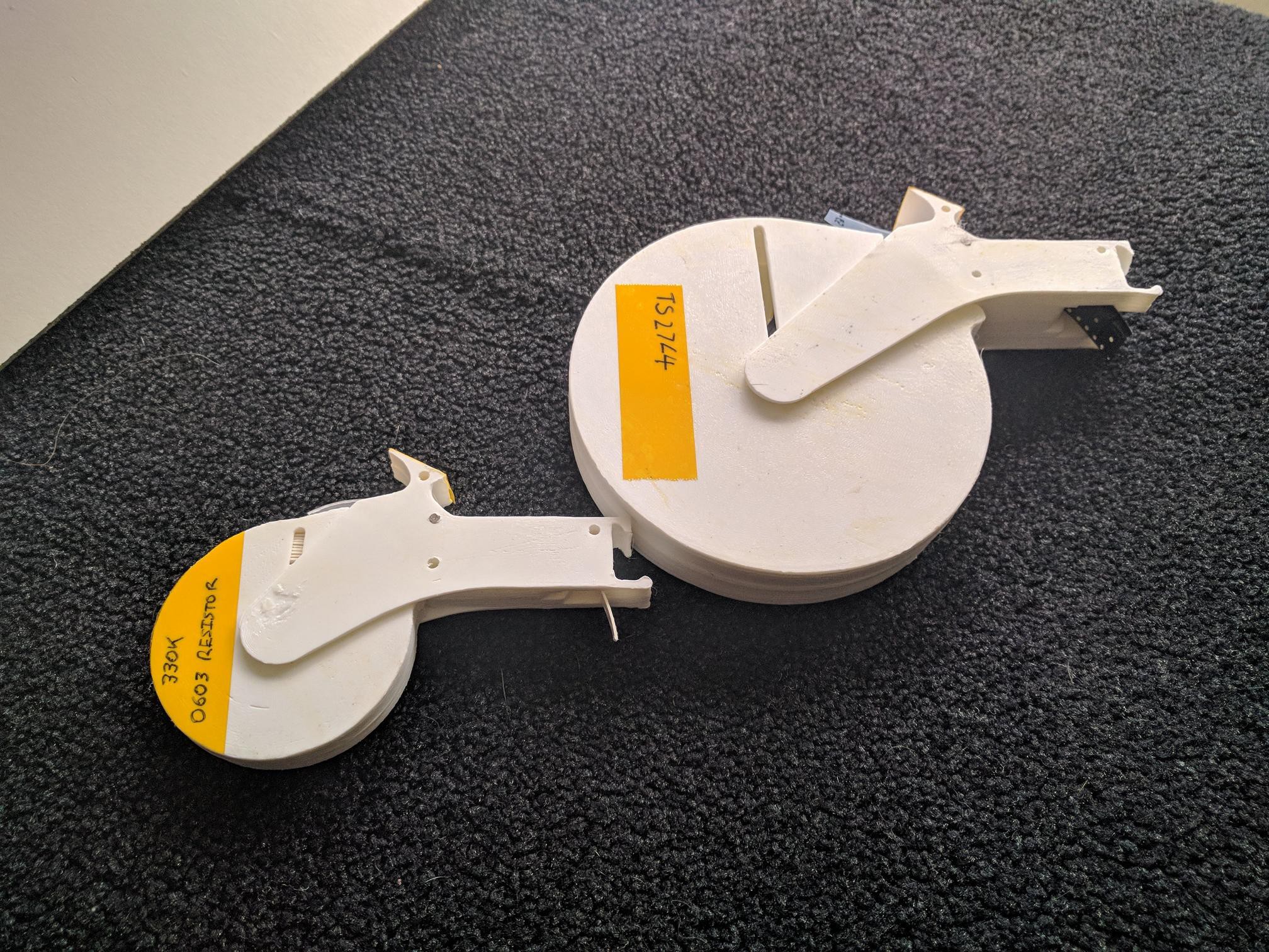
This is the result of many iterations and a couple of months of development, sometimes you need to work with something for a while to really get to understand what's good and what needs improving.
![]()
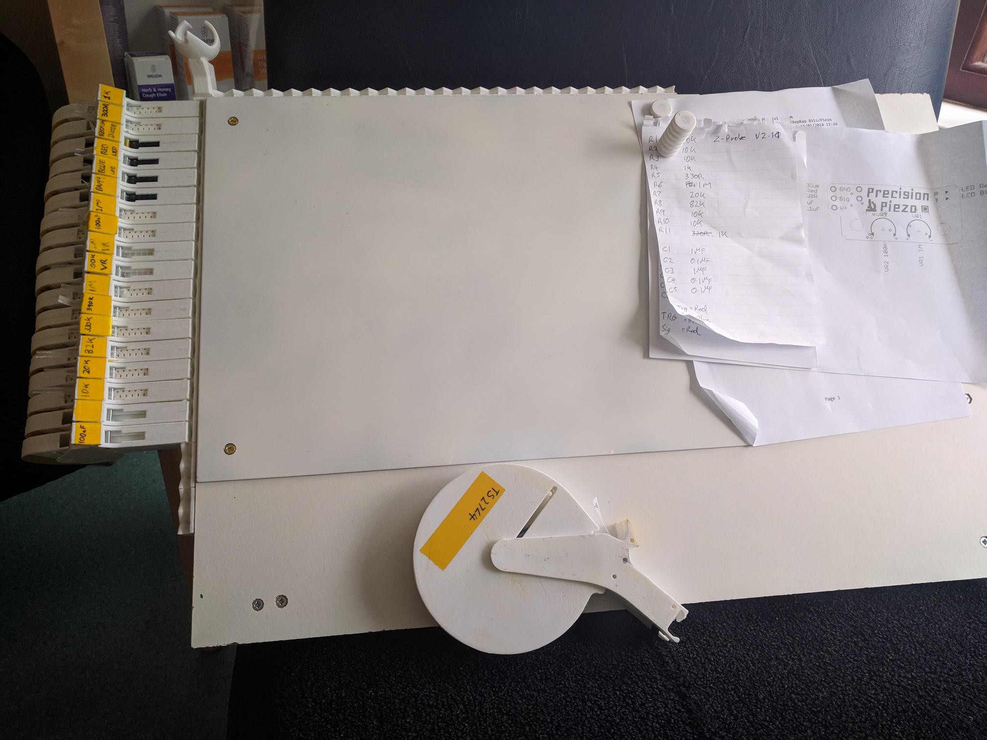
I use these feeders in a number of sizes, a small 8mm tape feeder on the left and a larger 16mm feeder on the right. The 8mm feeder will hold about 2M of paper tape or roughly 500 components. I've never filled the larger feeder to capacity but it will probably hold many hundreds of parts. The spools are removable to allow refilling and potentially swapping of components though currently I use one feeder per component value.
![]()
The feeders clip onto the side of an assembly board which then clips to the front of my bench, this makes assembly much more comfortable. Mounting clips along the side and top allow the feeders to be clipped wherever it's convenient. A steel sheet on the front of the board allows magnets to be used to hold PCB panels for assembly and at the top left of the board is a holster for my vacuum pick up pen.
-
SMD tape and feeders
02/11/2018 at 13:49 • 0 commentsOne of the first challenges facing someone who wants to use SMD components is their size which ranges from small to subatomic, to make them easier to handle and allow machine placement passive SMD components are almost always supplied on tape. SMD components on tape sit in a little pocket with a clear cover tape to keep them in place.
Having loose tape floating around the bench is a recipe for frustration, because they've been cut off a spool they wont lay flat and they're dying to swipe across your carefully populated board and ruin your hard work.
![]()
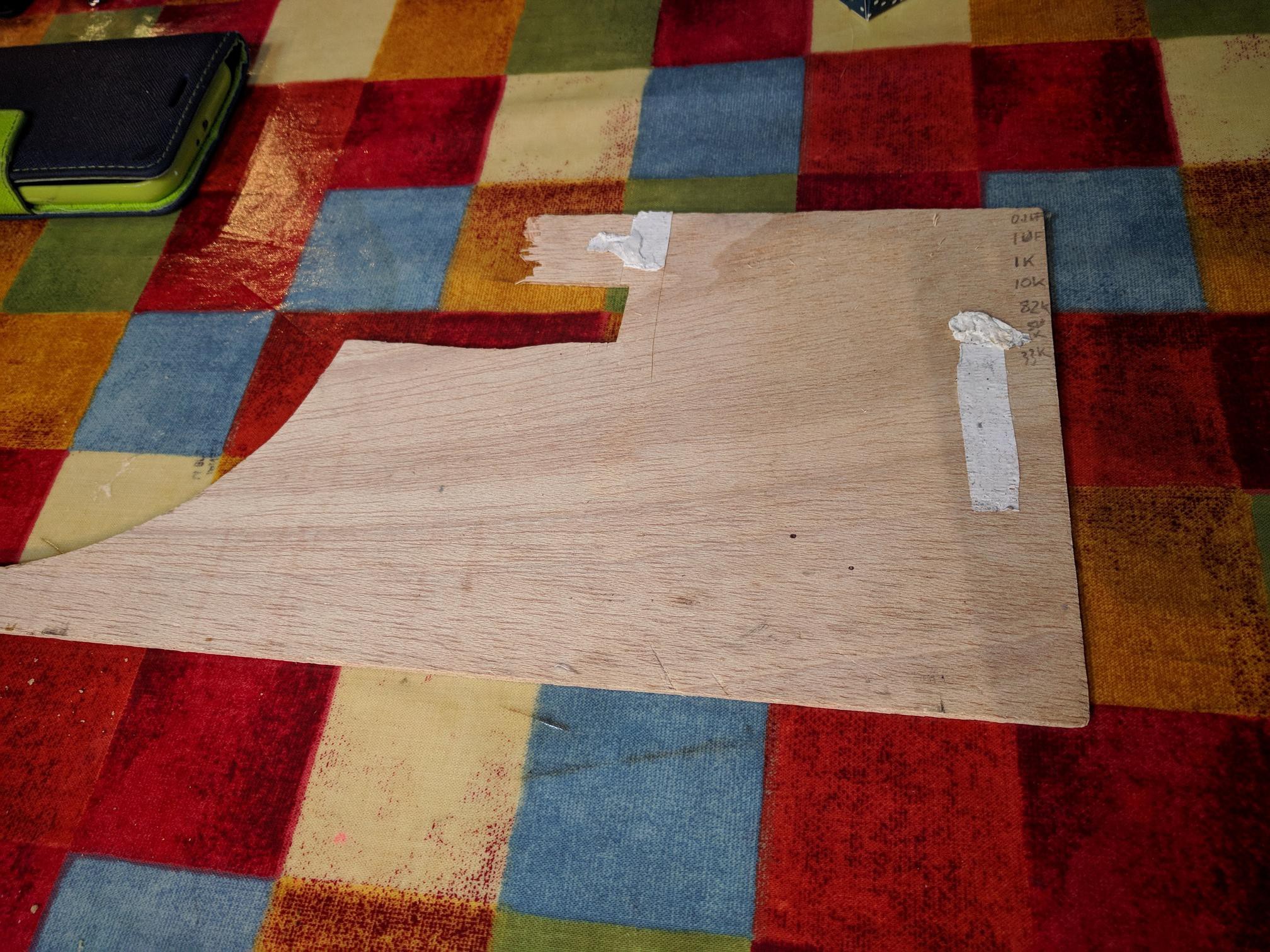
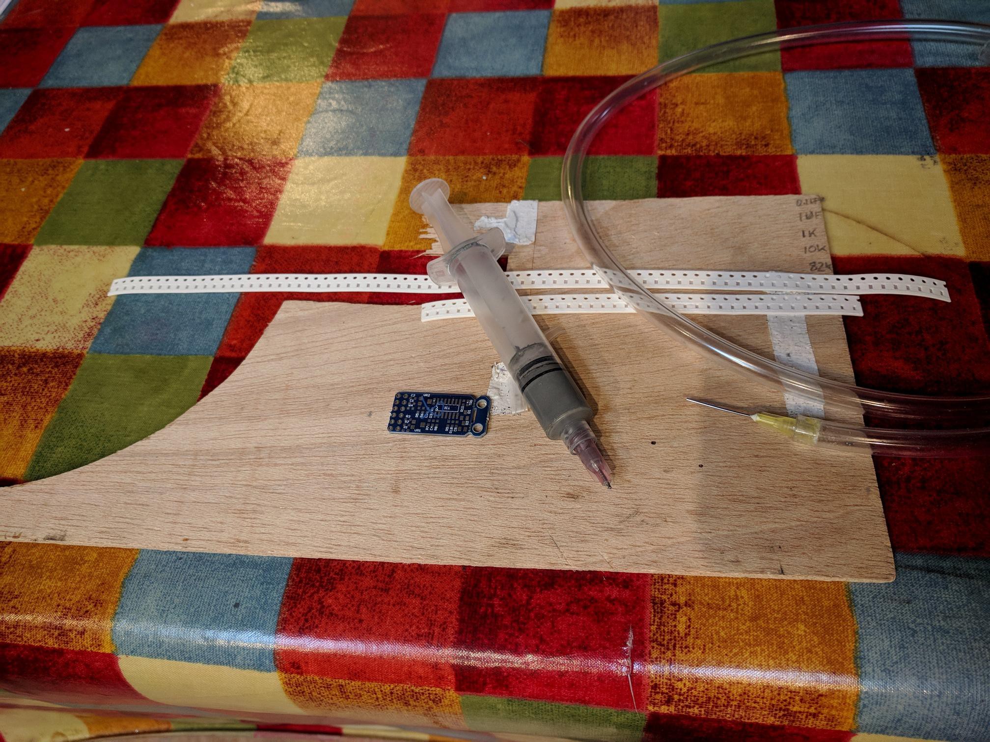
My first solution to this problem was to stick the tape down to a scrap of wood with double sided tape, it's easy, it's effective and it's cheap.Once I started making bigger batches the shortcomings of the Wood-n-Tape technique became apparent, you can only stick down so much tape so I would run out of certain values and surprisingly, picking from a different location each time slows things down more than you'd think.
![]()
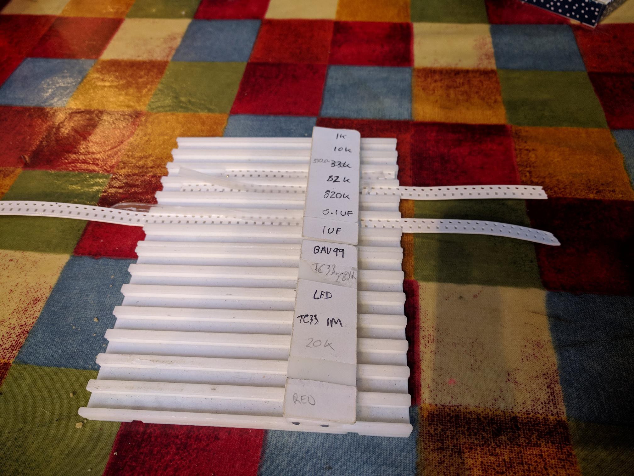
My first attempt to engineer a tape holder/ component feeder consisted of slots for the tape and somewhere to label what's what. What can't be seen very well in the picture is that the cover tape can be threaded underneath the labels around a shaft so that when the cover tape is pulled back it advanced the tape and exposes the components one at a time, in the same place, for picking.
-
In the beginning...
02/10/2018 at 11:58 • 0 commentsOnce the main development of the circuit had been completed, first on a breadboard followed by a stripboard prototype I decided to produce a small batch of PBCs. At this point I did not know whether there was a market for this idea, I had never had PCBs produced professionally nor had I used SMD components or solder paste. I ordered 12 bare PCBs from OSHpark and set about assembling them.
![]()
The equipment used for those first boards was as basic as it comes but I learned a lot. Shown in the image is almost everything you need to assemble small numbers of PCBs, the only thing not shown is the heatgun I used to reflow the boards. My intention in this project is to look at each of the tools in this picture in turn and show how it's changed as I have gone from essentially a one-off batch of 12 to series production. We will be looking at, in no particular order;
Component tape holding
Solder deposition
PCB holding
Component pickup
Reflow
Along the way I'll try to touch on the lessons I've learned regarding PCB layout for easy hand assembly.
Small scale SMD production
Trying to document the development of my processes for small scale manufacture of Precision Piezo PCBs
 Idris
Idris