Chris Low
-
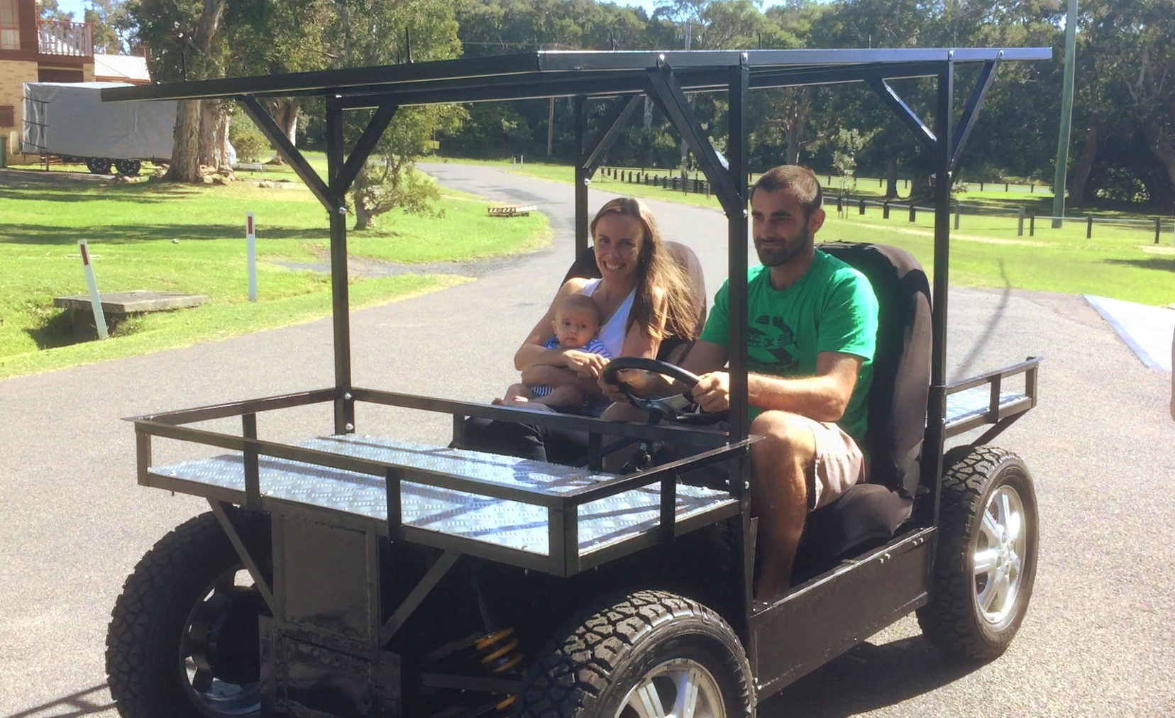
Mk3 in Action
04/08/2016 at 08:22 • 0 commentsA quick video of testing out the vehicle before we loaded it on the container.
-
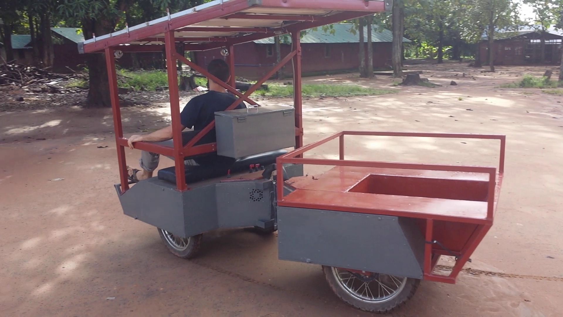
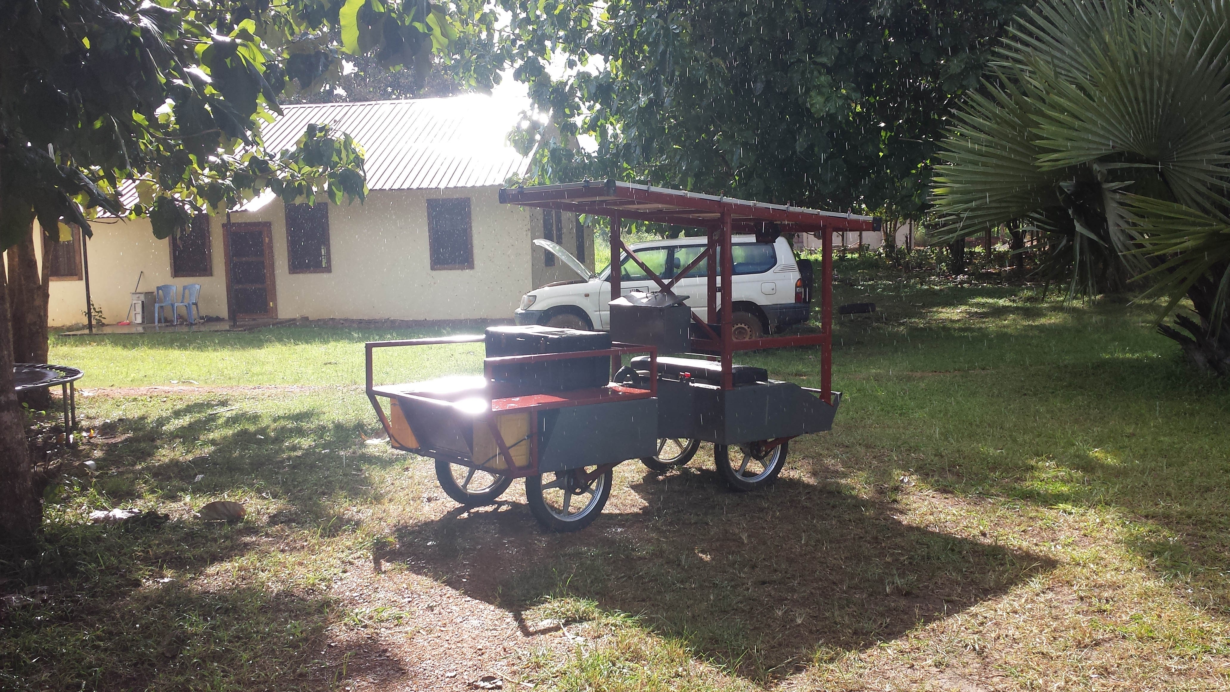
Mk3 "Finished"
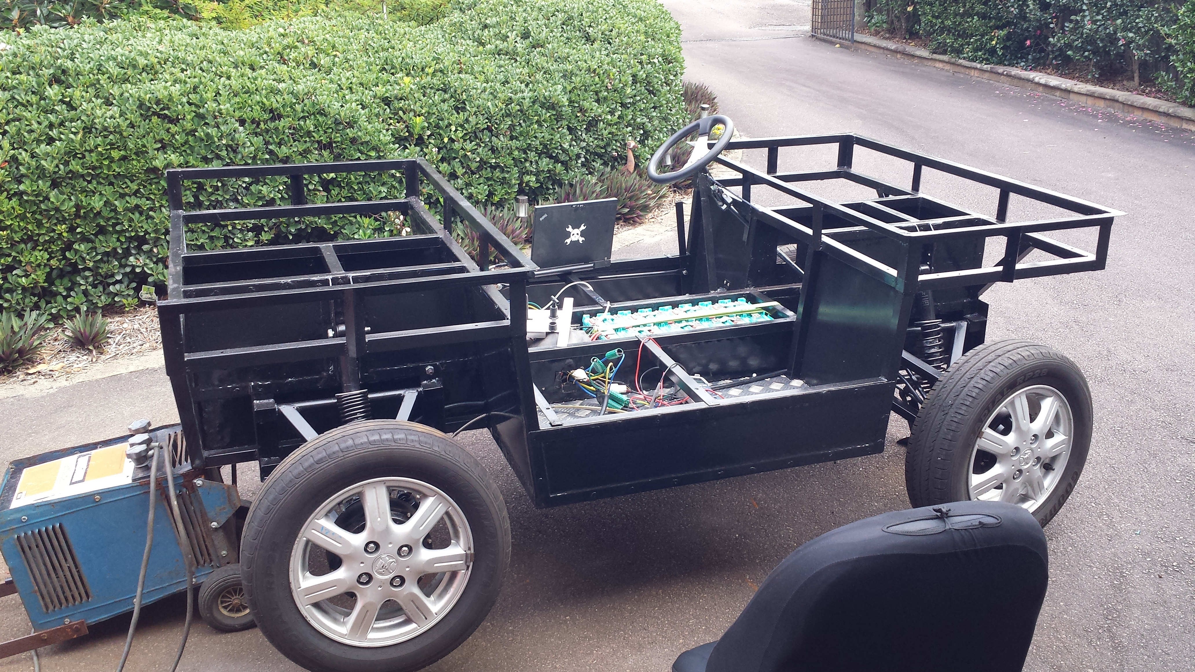
04/08/2016 at 02:17 • 3 commentsI have been working really hard to finish up the mk3 prototype while I have been back in Australia. This has been a pretty intensive process as this is a completely different vehicle from the earlier prototypes. In a few short months I have had to design, source components, and build this new vehicle in order for it to be put on a container headed to South Sudan. Making it a bit more difficult was the fact that I didn't have access to much in the way of tools. The whole thing was made outside under the shade of an McDonald's billboard I set up for protection from the sun and rain. The only tools I had were some basic hand tools, an angle grinder, a borrowed cordless drill, and an old stick welder. Everything is essentially done except for some adding some light, my BMS, and the panels which are already in South Sudan. I will try to write some logs about specific components, but in general the drive train consist of 4 1000W QS Motor hub motors controlled by 4 Kelly KLS sine wave controllers powered by 60AH 16S GBS LiFePO4 batteries.
Here are some photos of the build unfortunately I was rushing so things were
not very well documented:
![]()
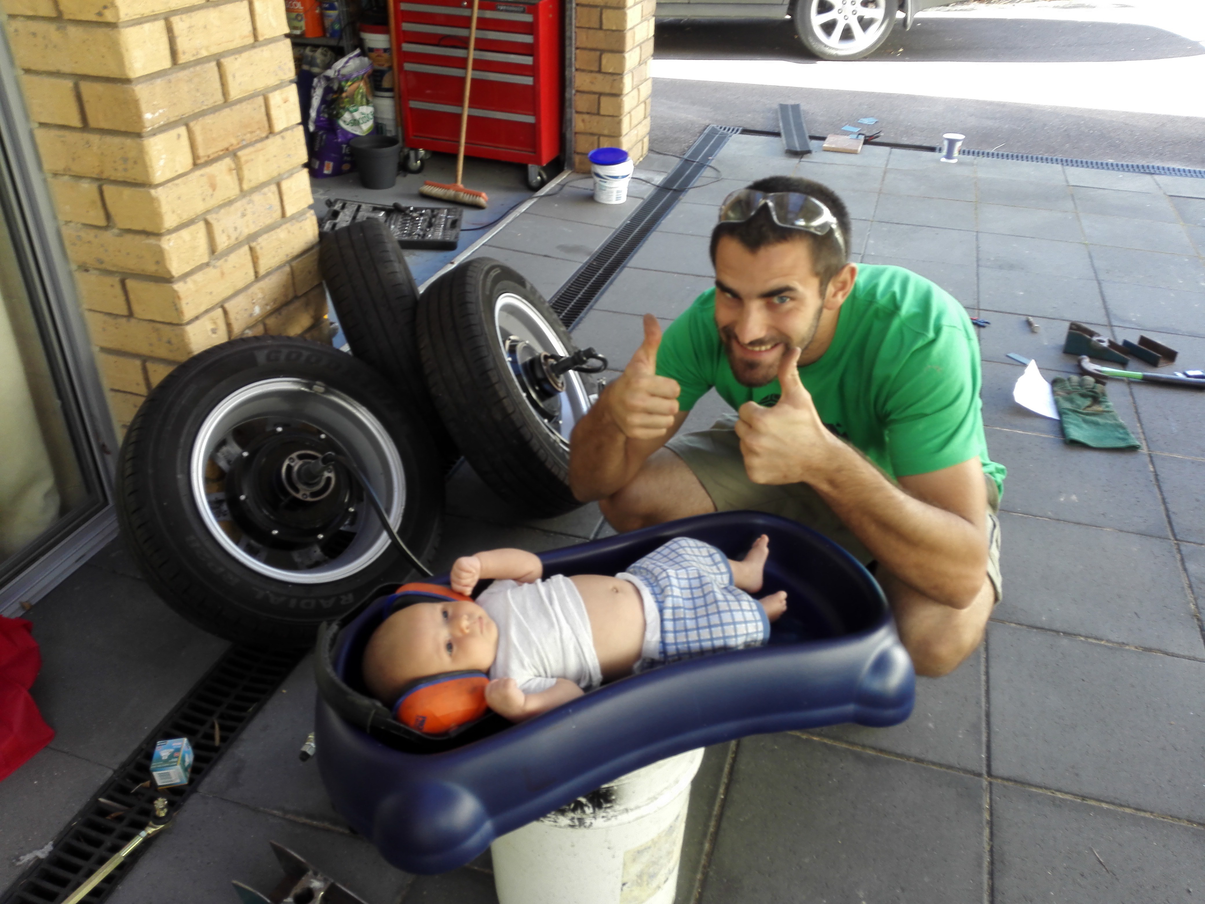
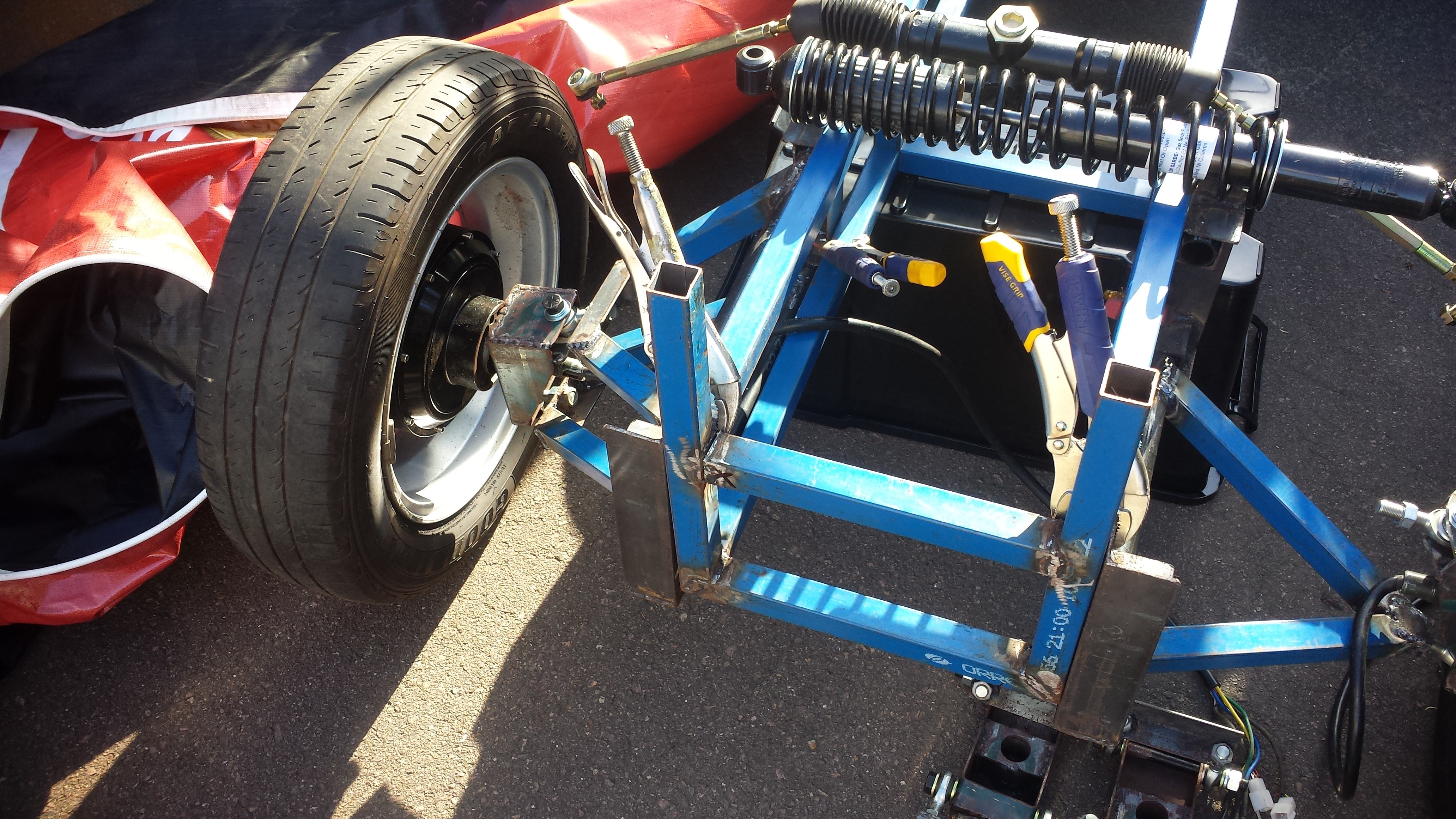
Inspecting the new hub motors. The rims are from a wrecked Holden. I had to modify them a bit to properly fit the 60.1mm center bore.
![]()
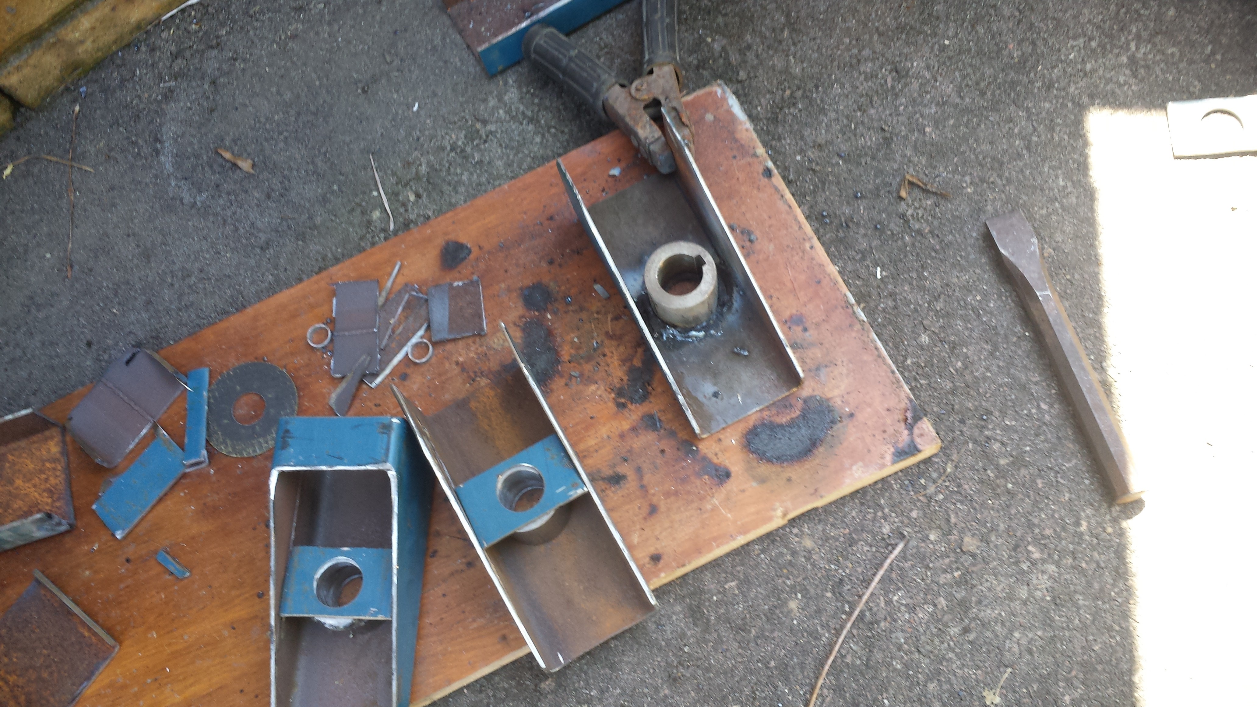
In the process of building the attachments for the motors. Found a new friend who bored out the steel and added the keyway.
![]()
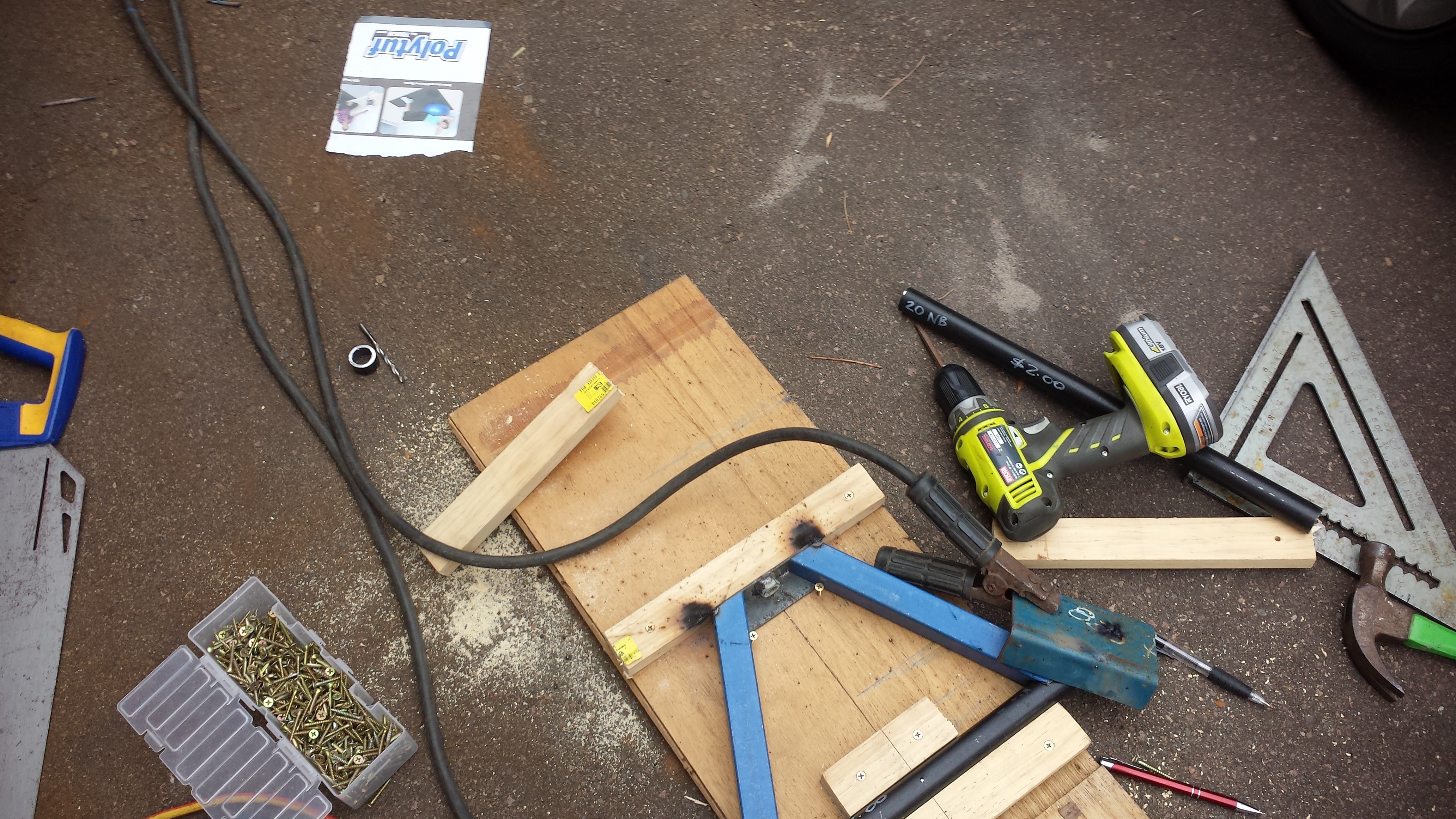
Building the upper a-arms. Not shown is the huge amount of time that was involved in calculating things like king pin inclination, caster, camber, and lots of other steering geometry I had to learn as I went.
![]()
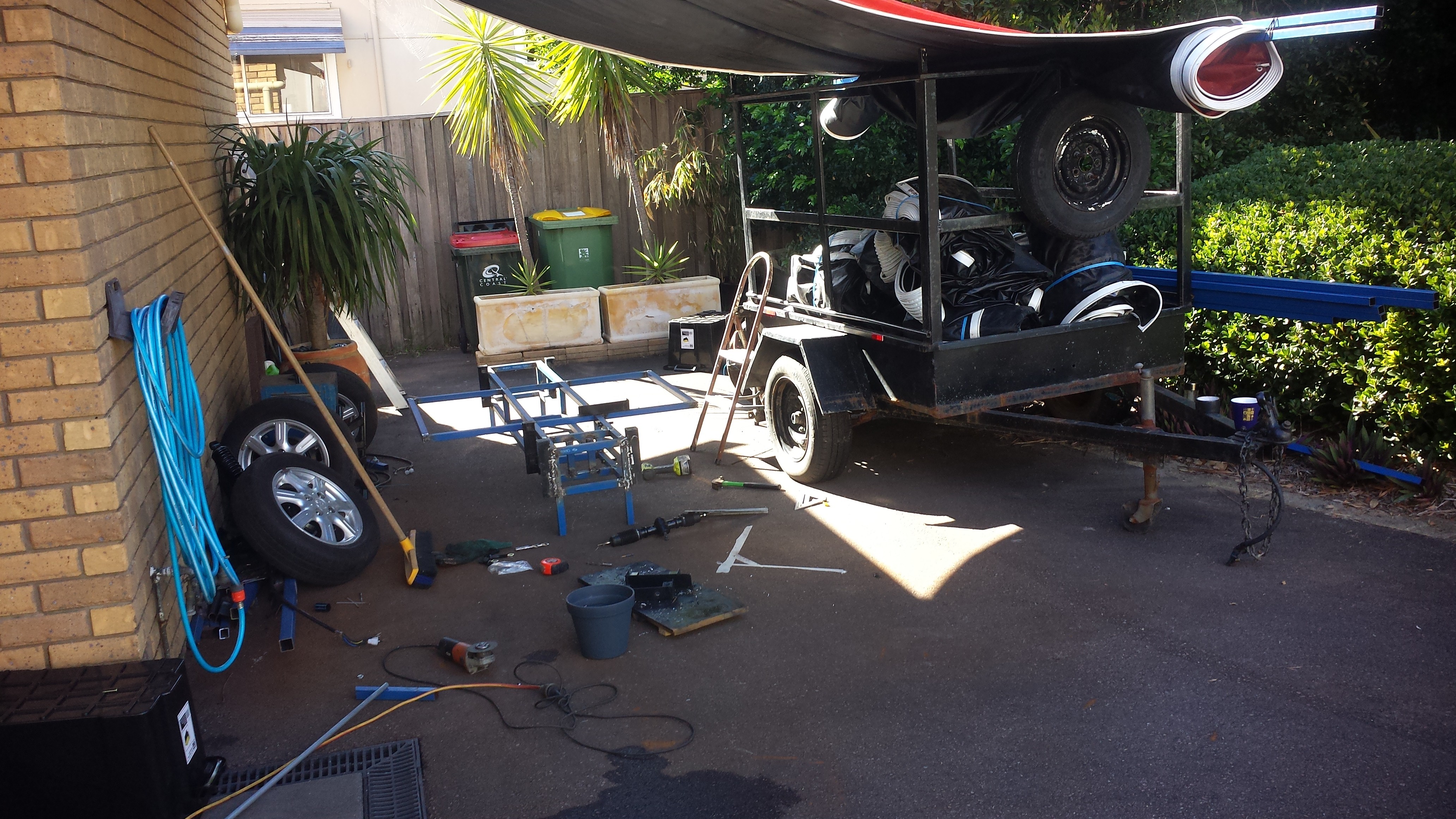
My "workshop" under an old McDonald's Billboard. I am taking these back to South Sudan to make light roofing structures.
![]()
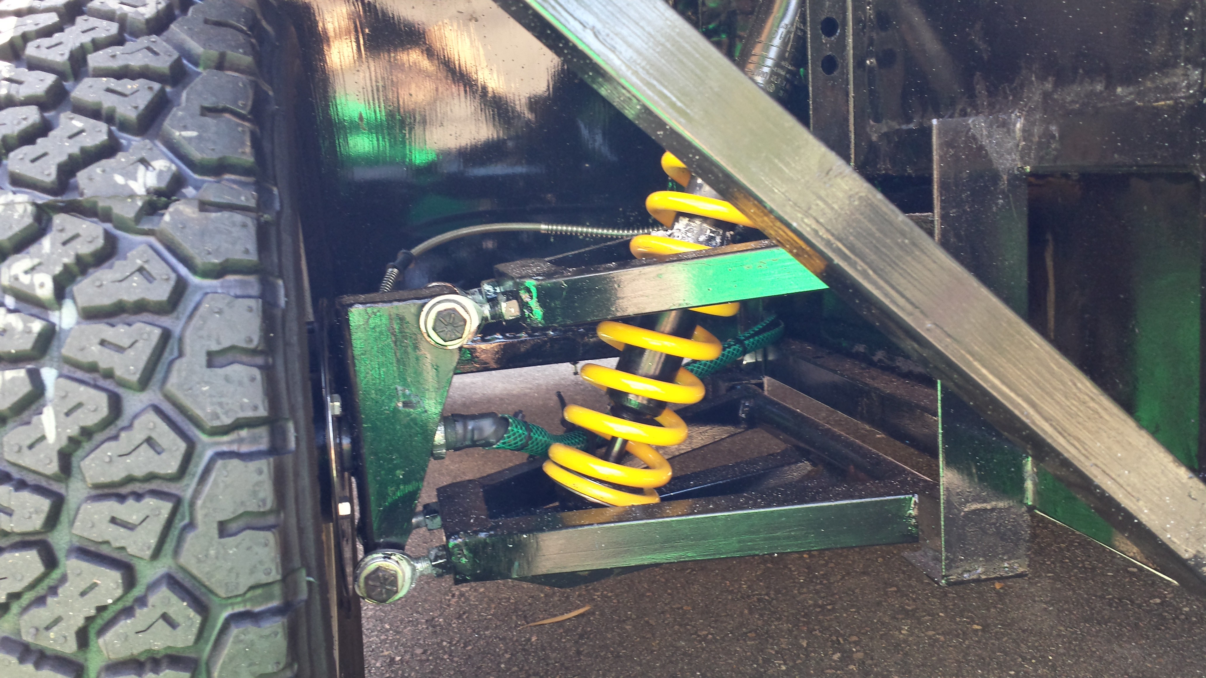
Working on the suspension.
![]()
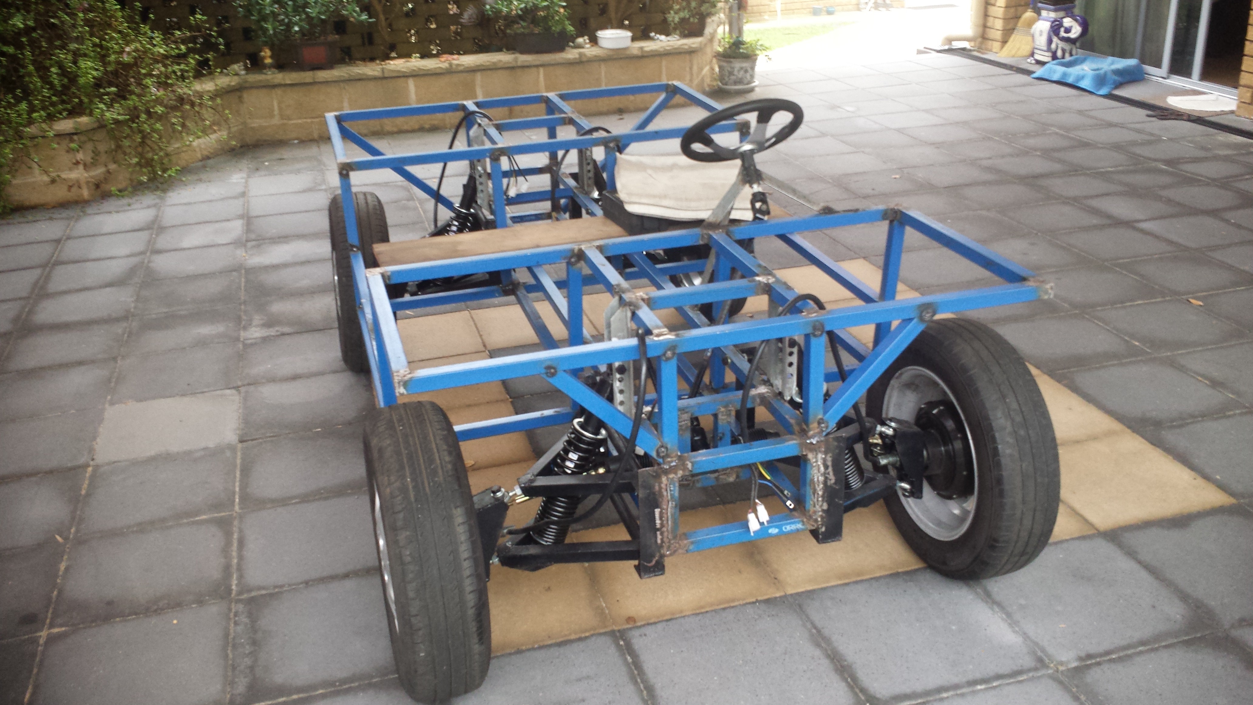
Frame just about complete.
![]()
early rolling testing.
![]()
Programming the motor controllers.
![]()
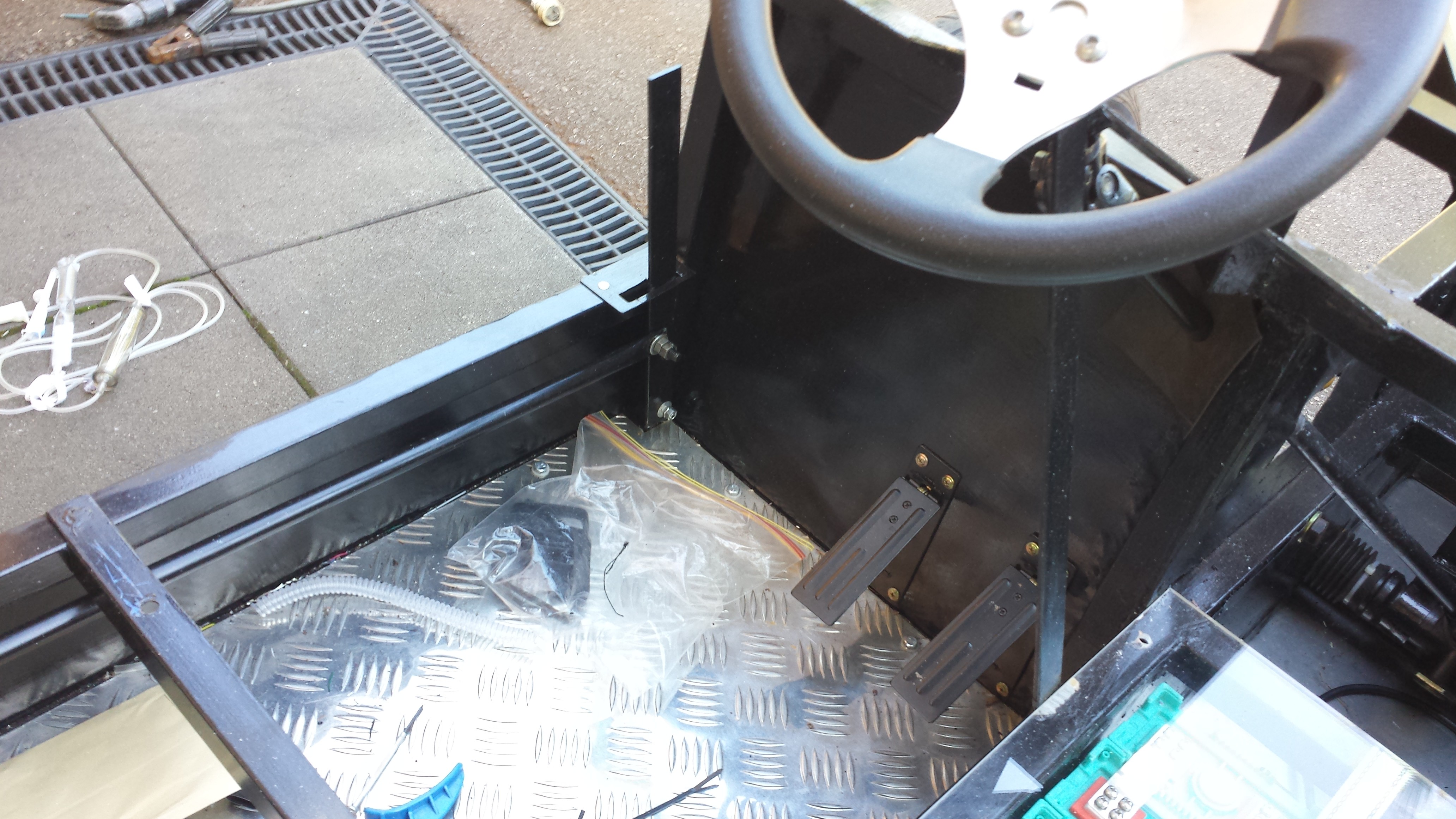
The right petal is the accelerator. Te left controls the regenerative braking. The handbrake controls the disk brakes and acts as the parking brake.
![]()
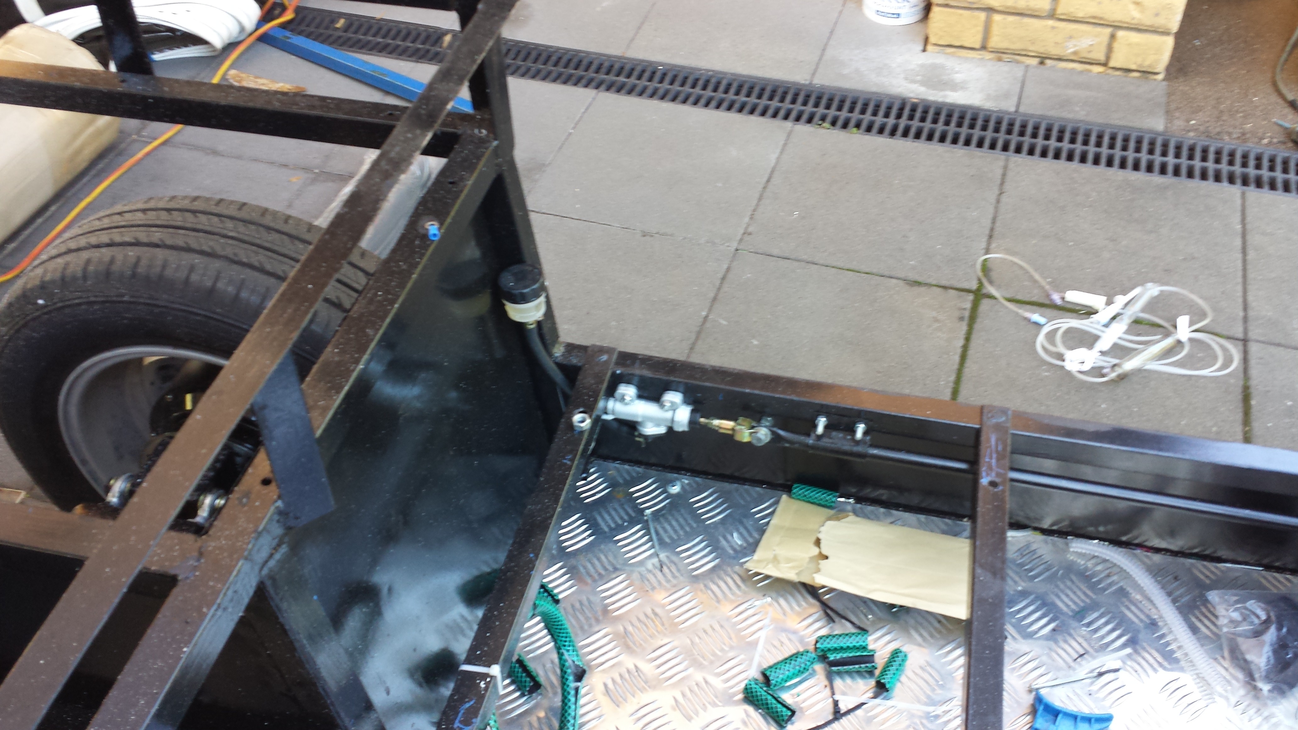
Mechanical linkage to the brake cylinder.
![]()
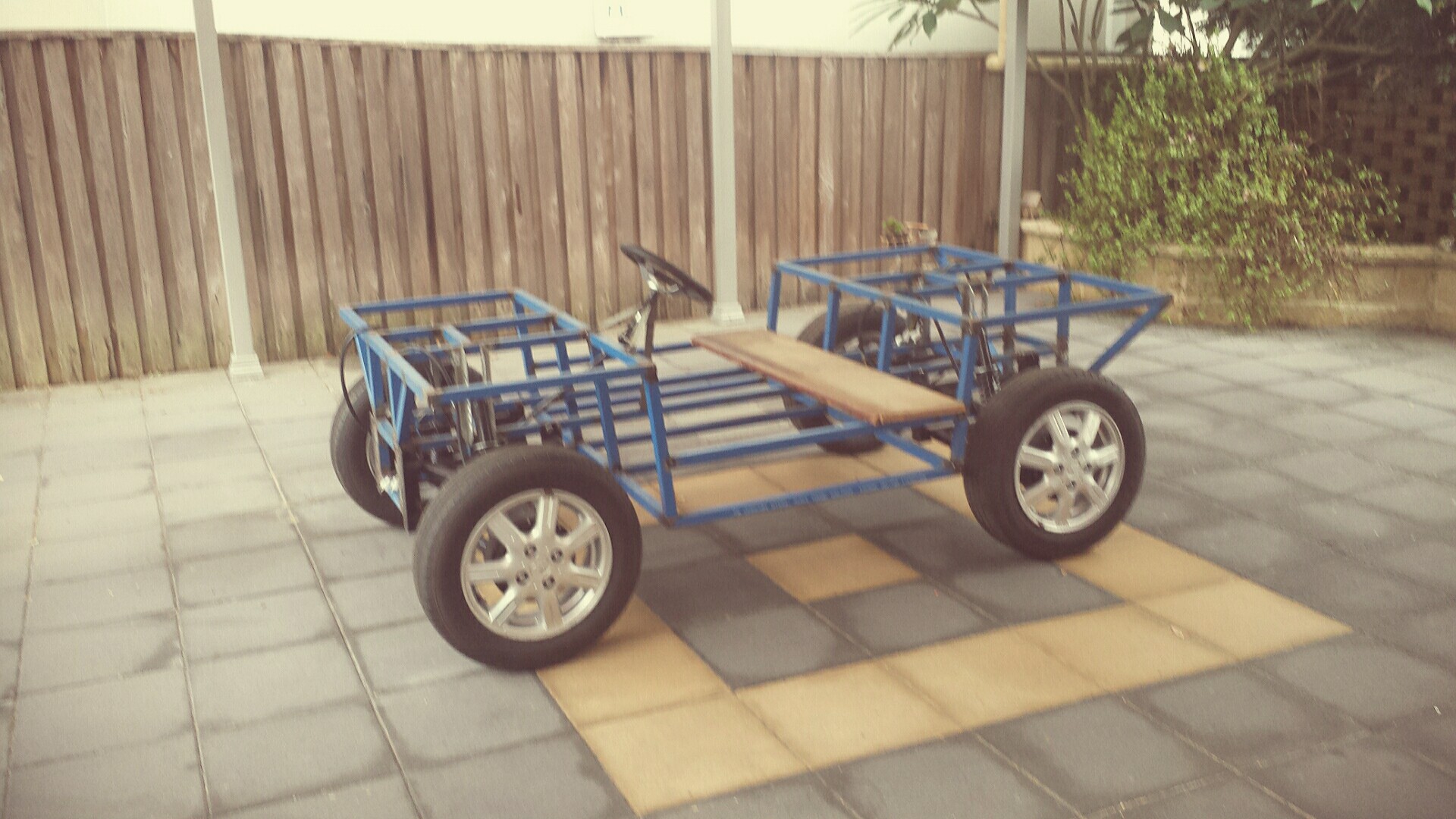
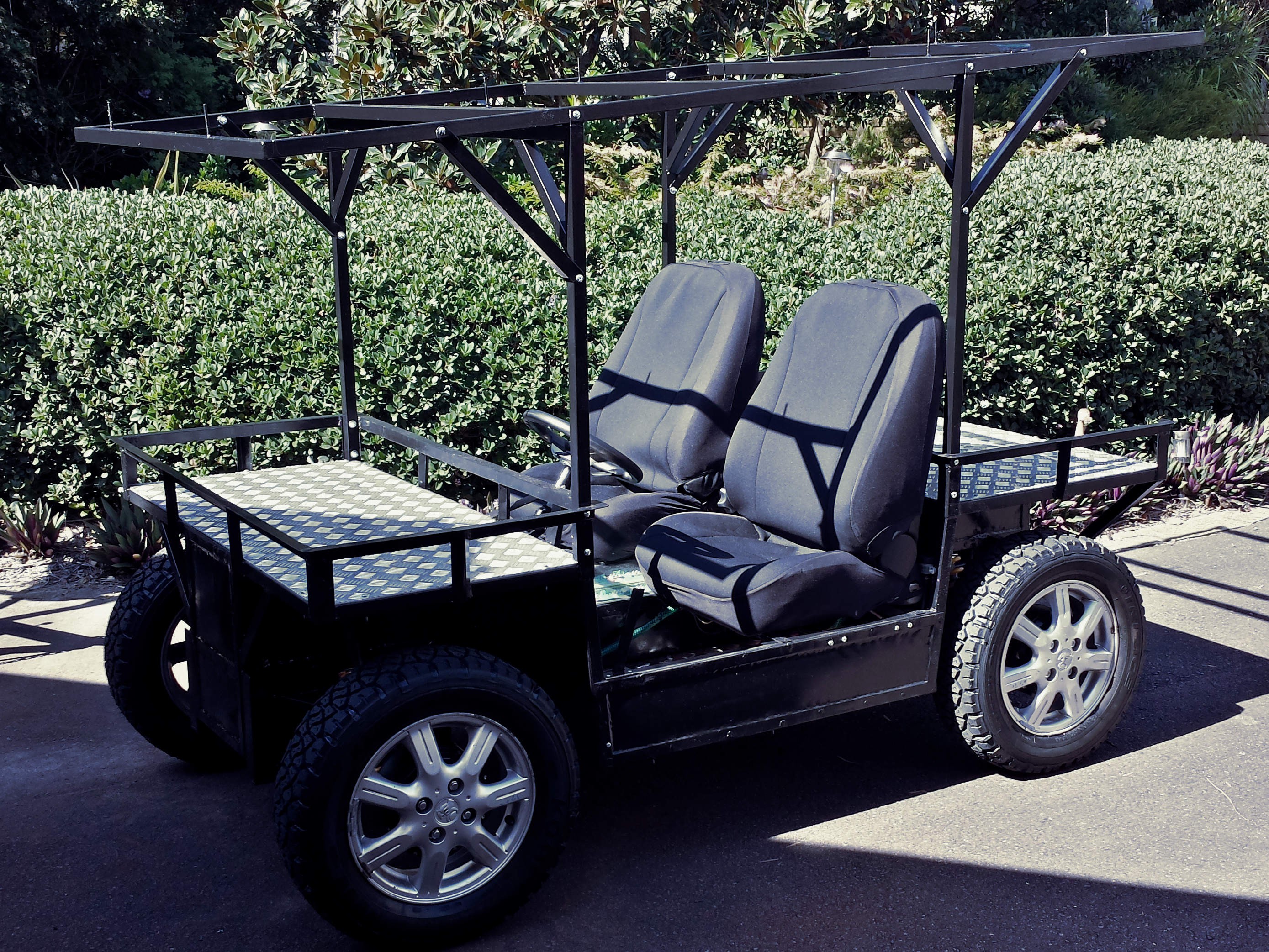
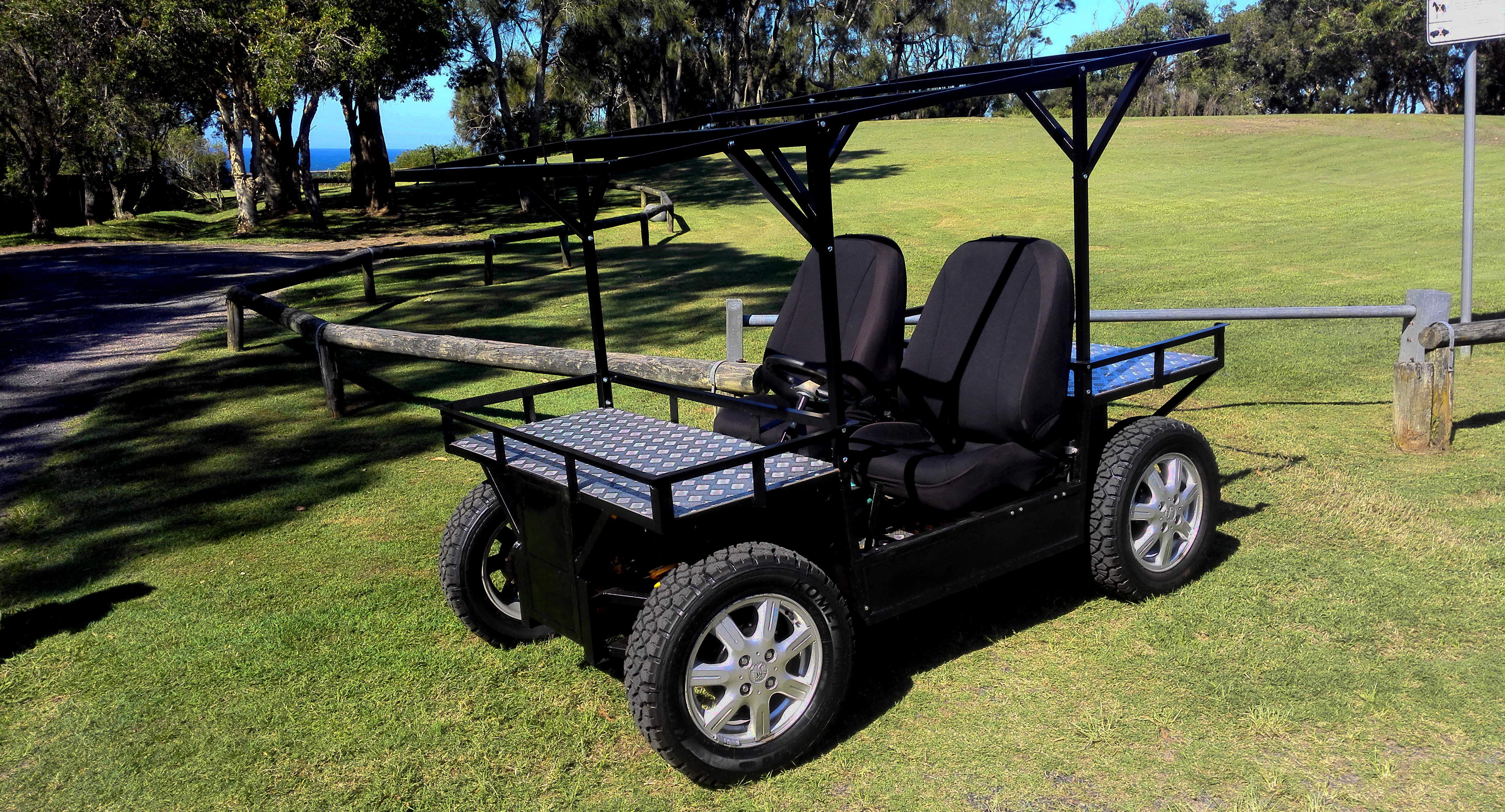
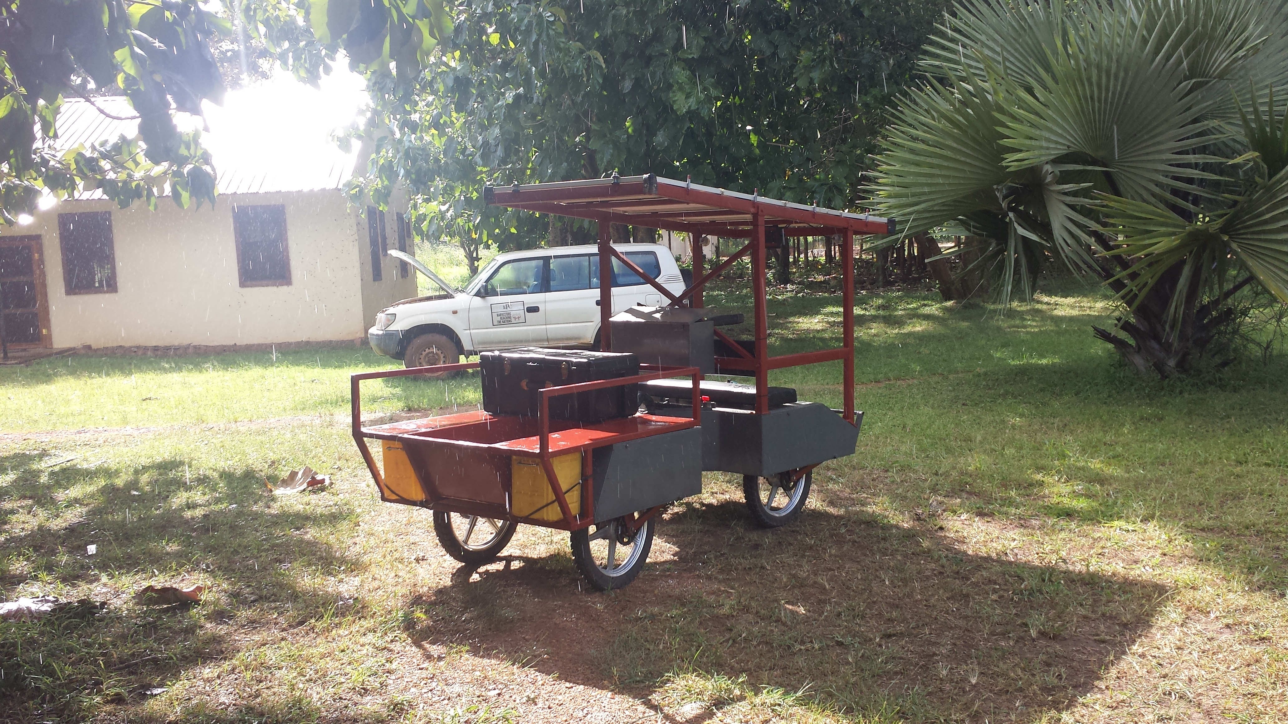
Just needs the panels.
![]()
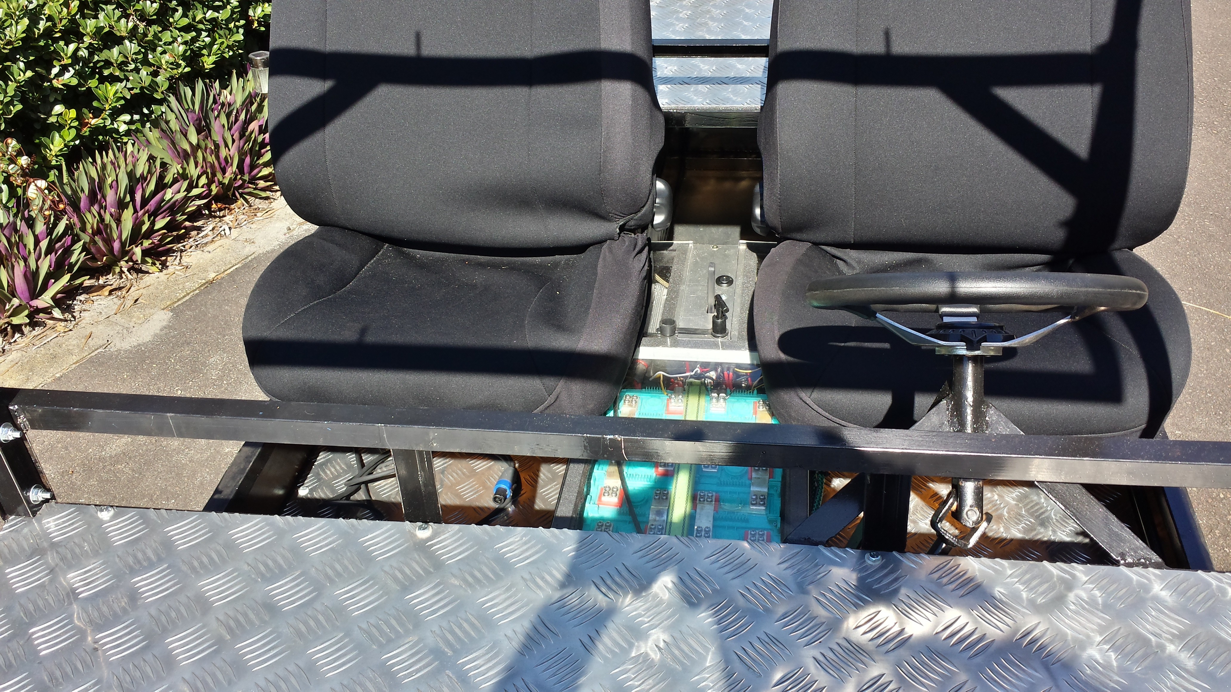
Simplified controls. Battery Shutoff, keyed switch, and a forward neutral reverse selector.
![]()
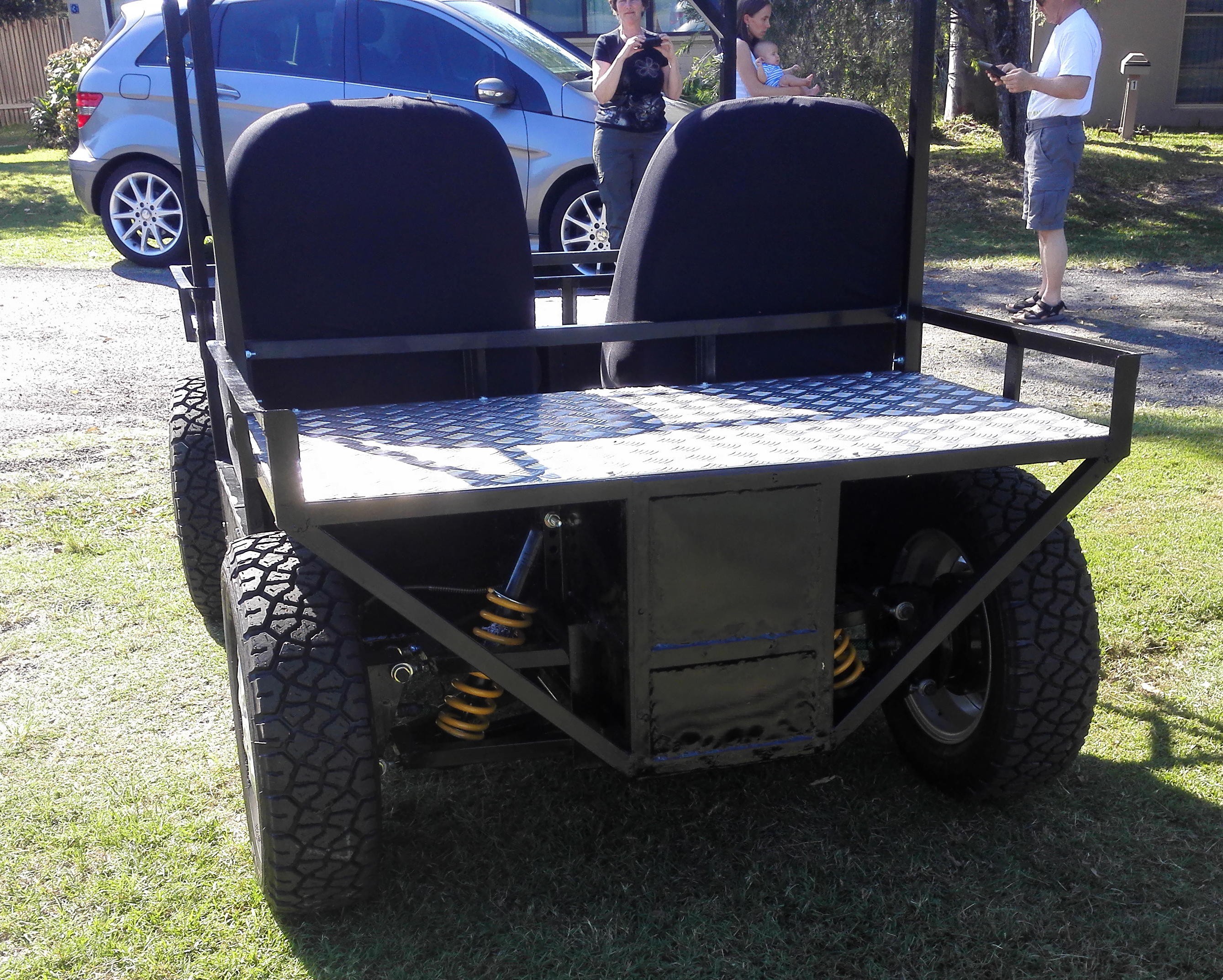
I had to change springs to beefier 400 lb/in.
![]()
![]()
![]()
New family car.
-
Updates
02/14/2016 at 04:39 • 1 commentI have been a bit distracted lately because my wife and I just had are first child. I am busy teaching him the finer details of hardware hacking, but I am worried he may not be picking things up as quick as I would like. ;) We have gone back to Australia for the delivery, and will be out of South Sudan until April. I have decided on a total redesign of the vehicle. The last version took some serious damage when it broke loose in the back of the truck it was being transported in. It gives me the perfect excuse to make some much needed improvements. My aims are to maximize efficiency and robustness. I have taken a number of ideas from the Luka EV project which can be found here on Hackaday. The guys behind that project have been hugely supportive and helpful. Their project is ambitious, and I think will really push forward EVs, and small builder manufacturing.
I have switched to using hub moters, Lifepo4 batteries, a more traditional rack and pinion steering system, and long travel a-arm suspension. Hopefully over the next few weeks I will be able to post new updates on the progress. Just wanted to let people know this project lives on.
Chris
-
Loading Up
10/27/2015 at 07:47 • 0 commentsJust a quick video of loading up the SUV in the back of the truck to start my journey up to Yida Refugee camp. I got to make good use of the winch which worked well, but sounds awful. Enjoy.
-
PID CONTROL
10/26/2015 at 18:37 • 0 commentsOne of the most difficult elements of this project to get right has been the PID loop to keep the vehicle tracking straight. Without it the vehicle can easily veer off course. I think the process of tuning the parameters took several years off of my life.
The first part was getting information about what the angle between the front and the back. I started out by creating a sensor using a ratiometric hall effect sensor and neodymium magnets.
![]()
![]()
This worked pretty well, but it was an incredible hard to set up. The output was very non-linear, and in the end I had to create a complete lookup table for all of the potential values. This was an incredibly cheap way to get absolute position feedback. It cost less than two dollars. As a long term solution it doesn't really work with what I am trying to accomplish because it would be really hard for someone to set up if they didn't know what they were doing. I also had to rebuild the center pivot which means I had to remove the sensor.
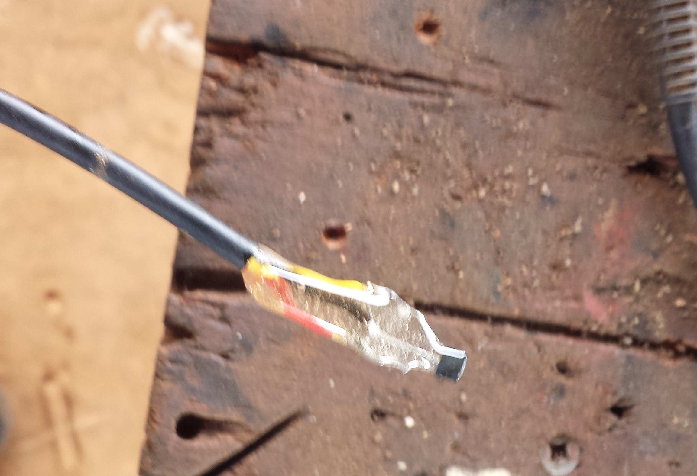
I then used a normal 10k pot. It worked for a while, but wasn't rugged enough and it failed. Unfortunately I didn't have any spares. I gutted a servo motor and used it as a pot. This has worked quite well so far.
![]()
I use this measurement to as the input of the PID loop. The setpoint comes from reading the joystick on the wii nunchuck. The output controls the turn parameter of the sabertooth controller.
Tuning this loop was pretty scary. There is a lot of power in these motors. When the parameters were out of wack it has a tendency to turn violently, There are some good dents in a couple of places from the sudden stops.
Now it is running pretty well, but I will try and tune it for a bit stronger response in the future.
-
Body
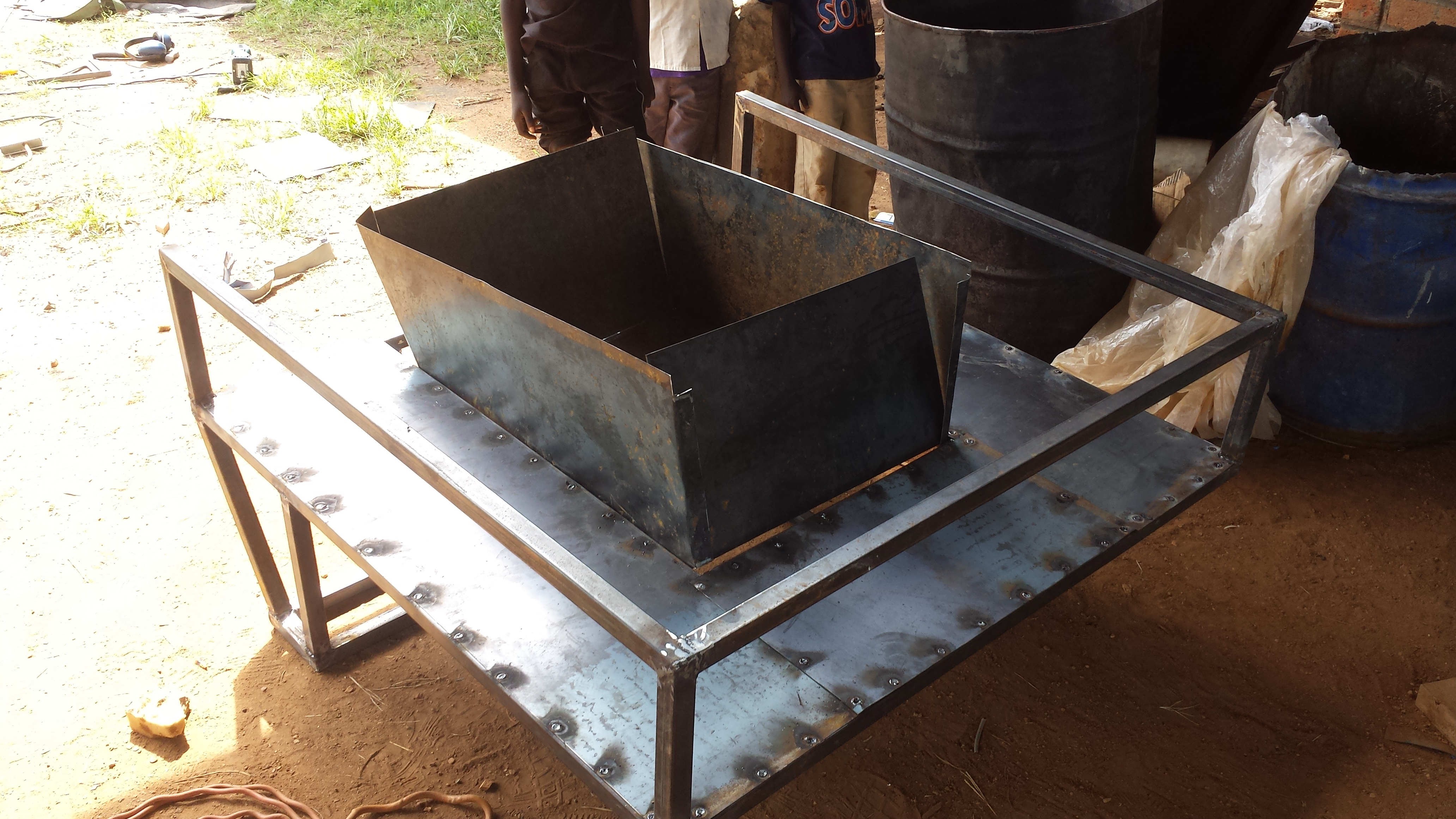
10/26/2015 at 16:12 • 0 commentsI have now finished the body, so I will give a brief overview, but mostly show off some photos. The biggest additions are a dumping bed and a built in toolbox.
![]()
![]()
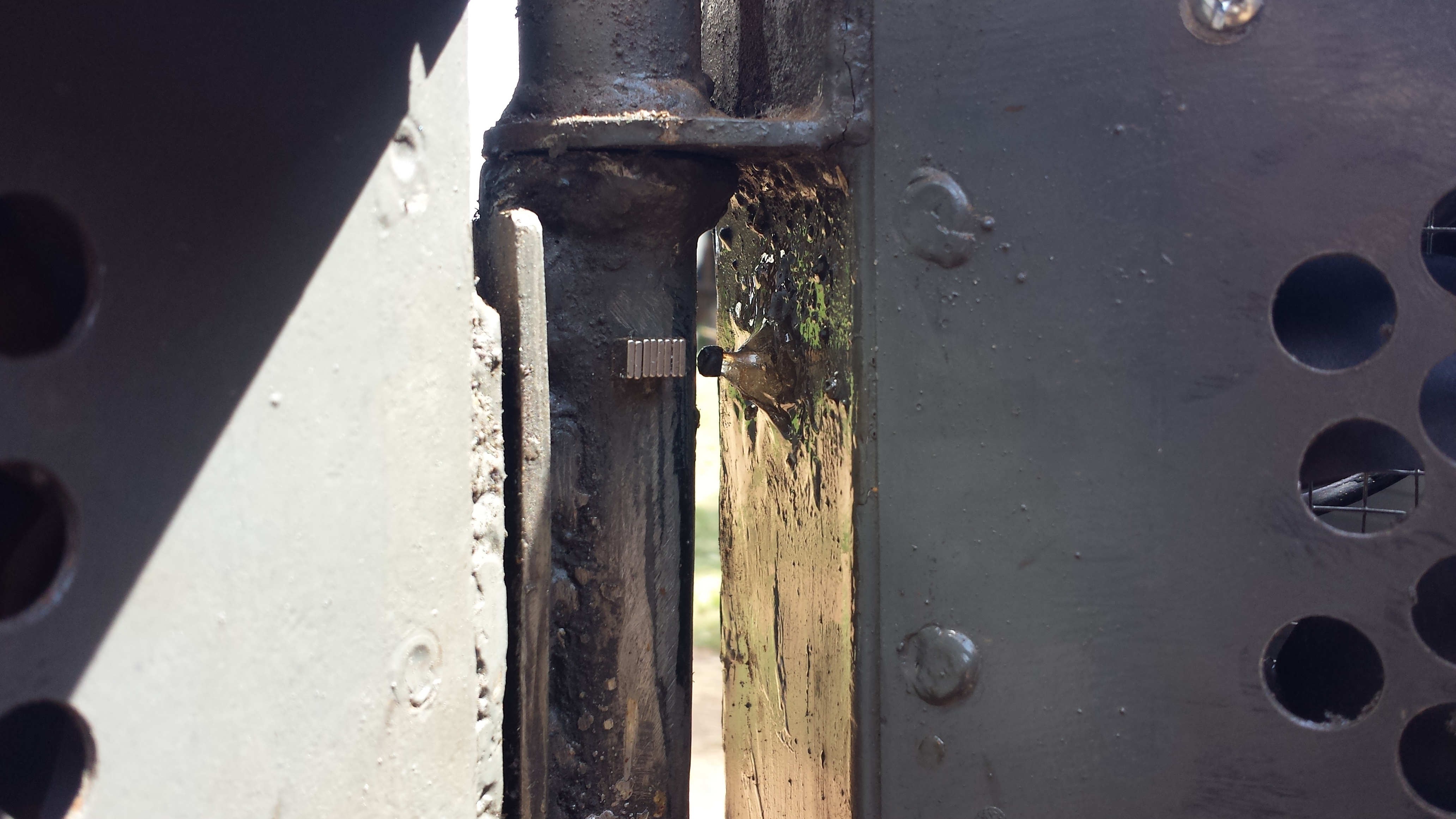
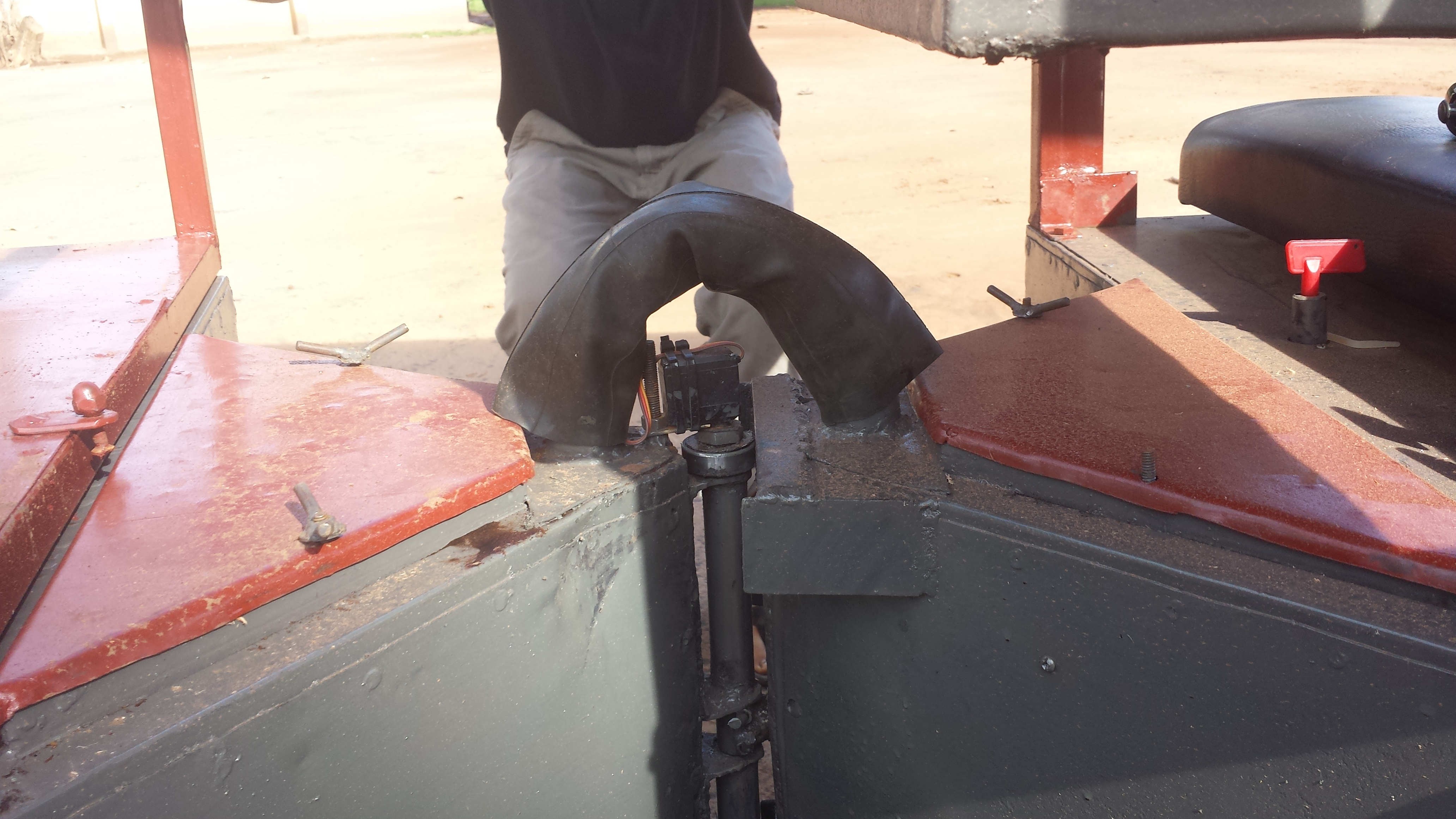
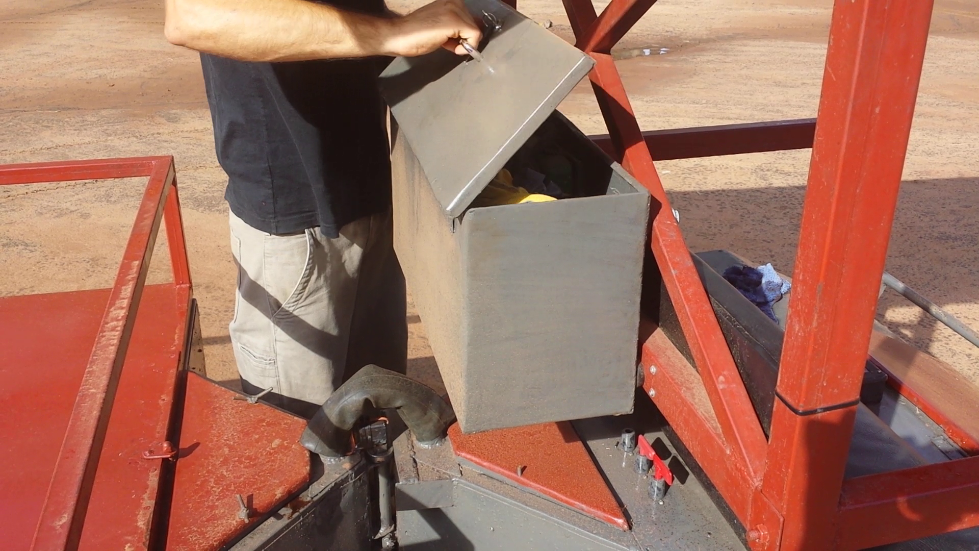
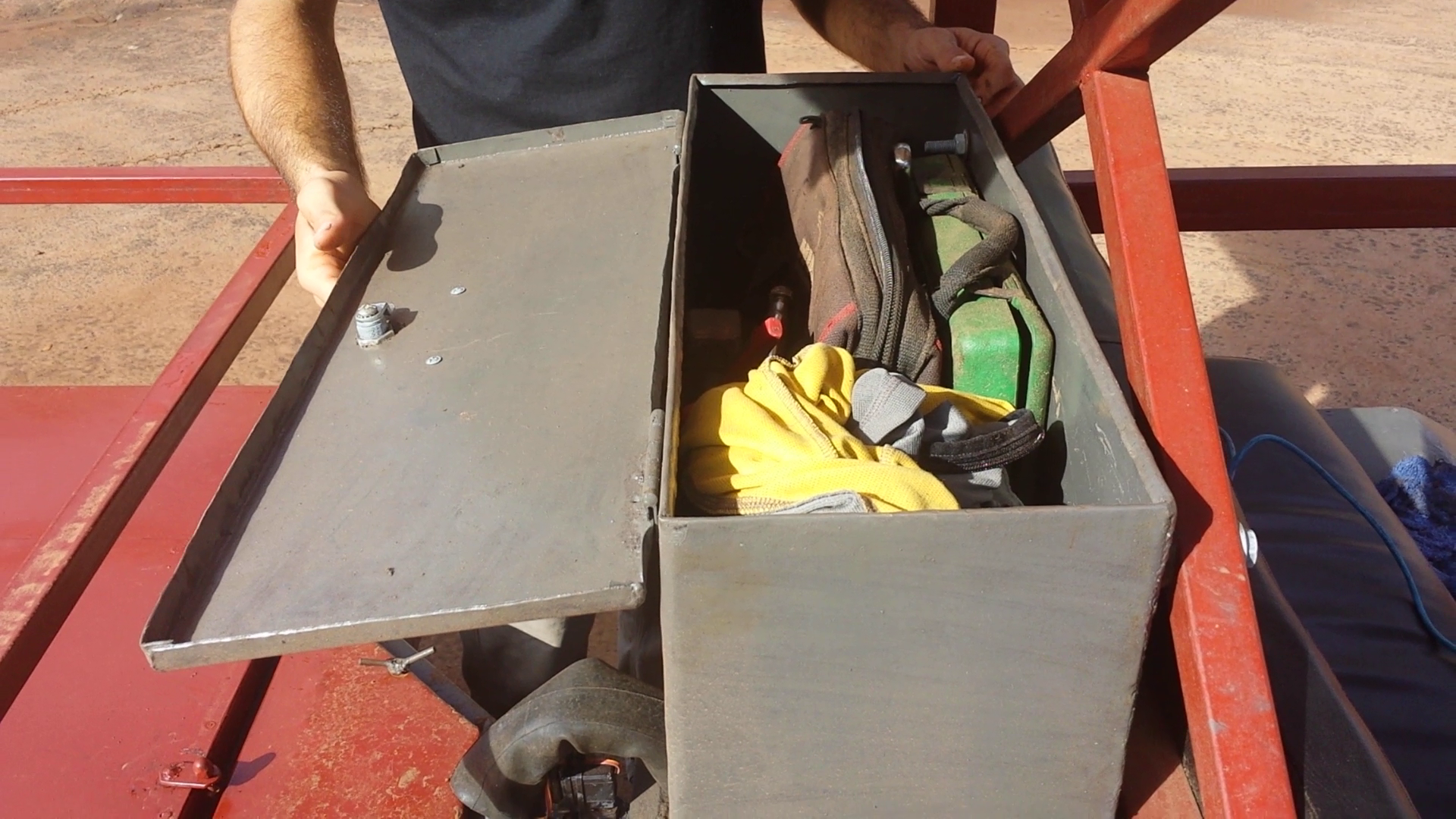
Here is the mounted toolbox. It is a nice size for the space available, and it is really nice to have lockable storage. The rubber tube connecting the two haves contain wiring. I ran it through two motorcycle inner tubes for abrasion protection and to keep water out. Sorry everything is really dirty. I was running a sander off the batteries earlier in the day and got sawdust everywhere.
![]()
All the storage in the vehicle is designed to be waterproof.
![]()
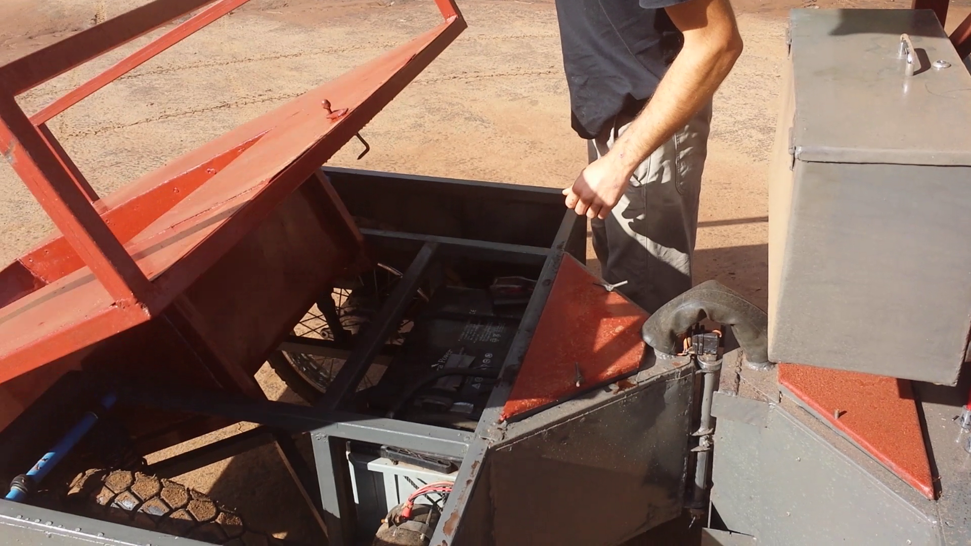
The rear bed tilts for dumping loads and for access to the rear wheels and motors.
![]()
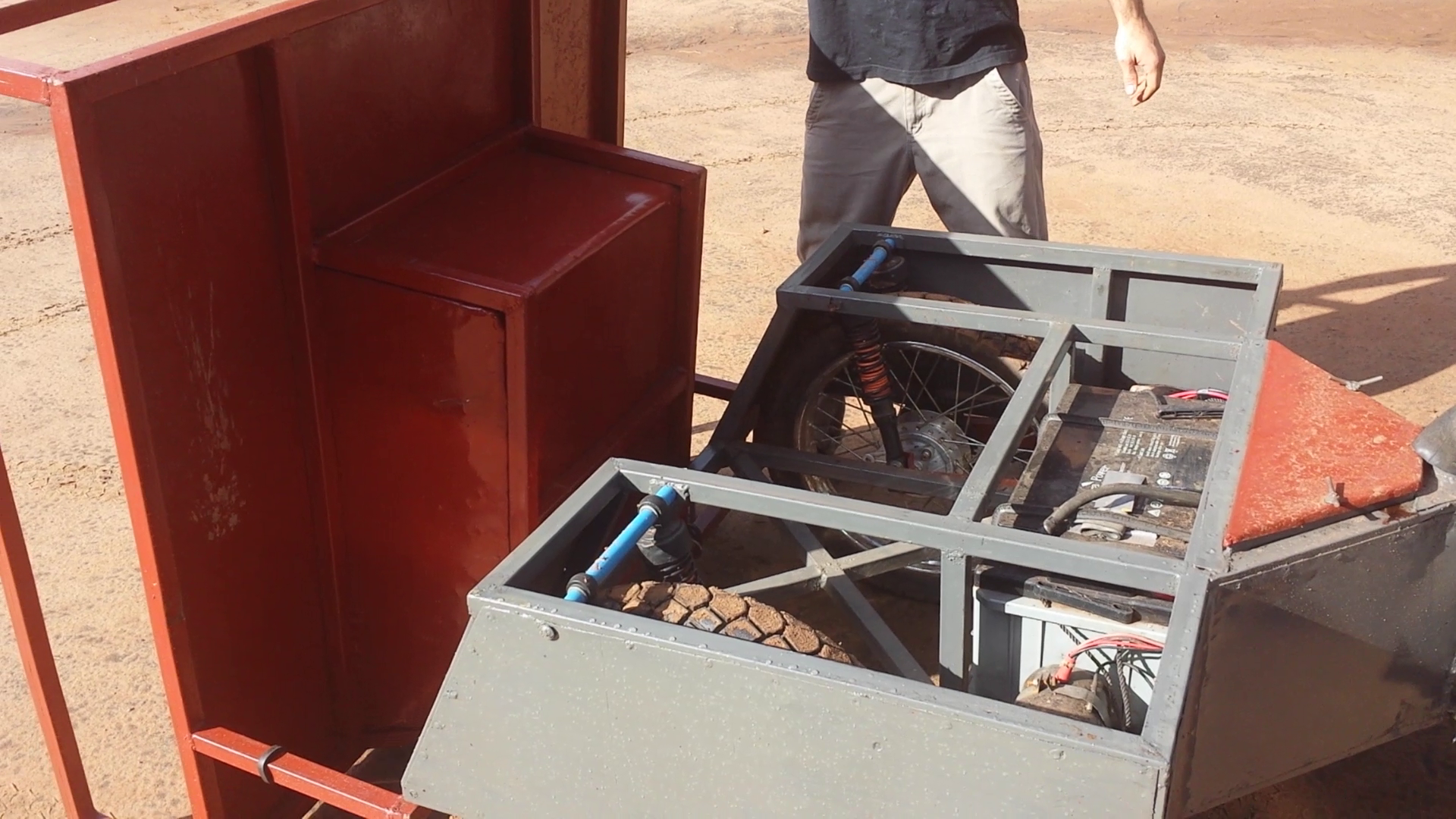
The bed rests at about 90 degrees to the ground. I hinged it closer to the center point instead of the end so it tips with less effort.
![]()
The areas in the back are used for storage. They fit these buckets which can hold things like ropes or extra tools. It is ice to have a place for them that is out of the way. There are some different wheels on the vehicle for this photo. They turned out to be terribly weak and I shattered two of them. I went back to the original wheels and lowered the suspension about 80mm to lower the center of gravity.
![]()
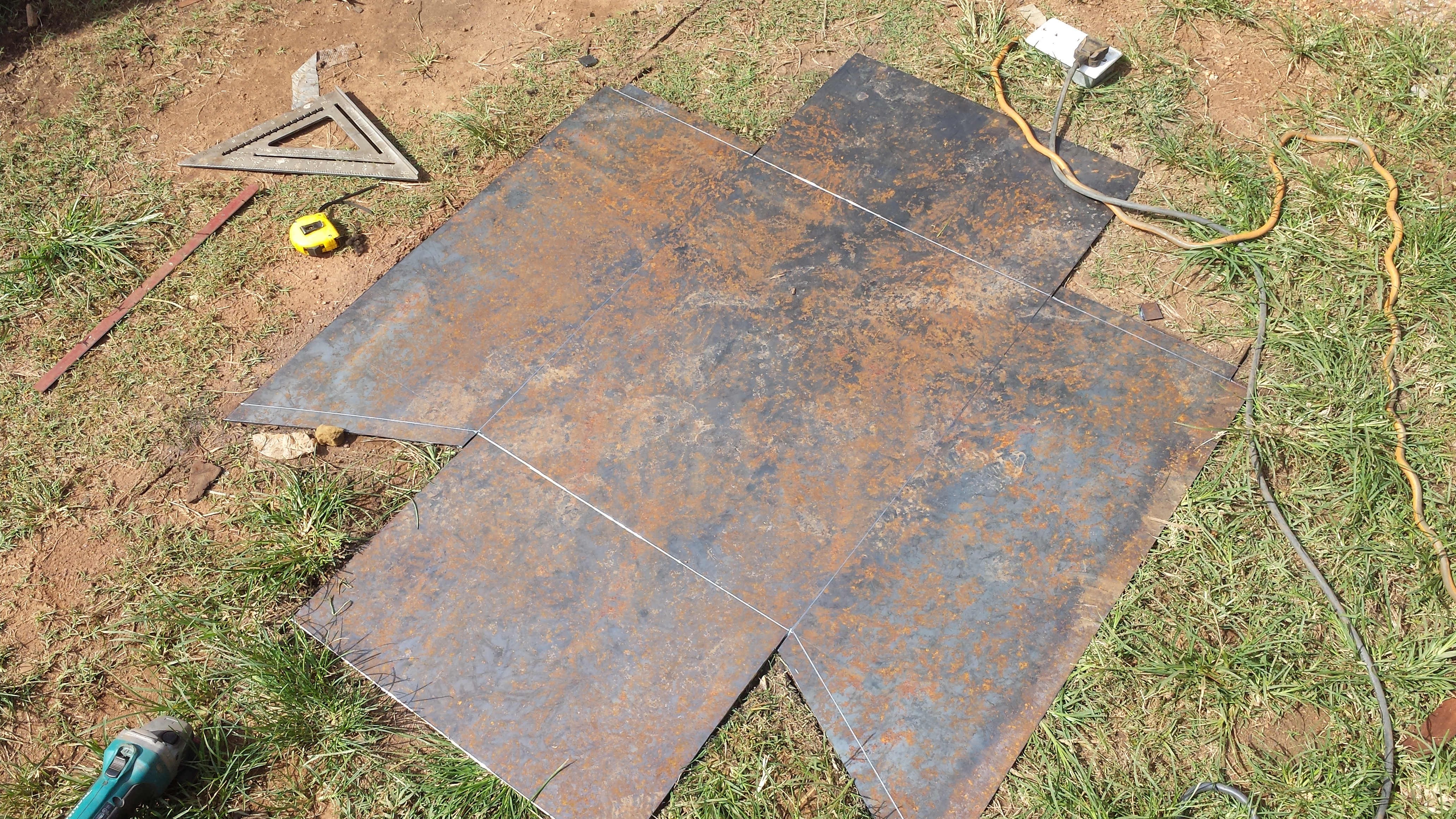
I made the back by first welding the hollow section frame. I then cut out the panels from a 1200x2400x1mm sheet of steel. I score the places where I want a bend, and then bend it with a hammer.
![]()
I then weld each sheet in place by burning through the sheet with the rod. The resulting bond is really strong, and it is a very fast process.
-
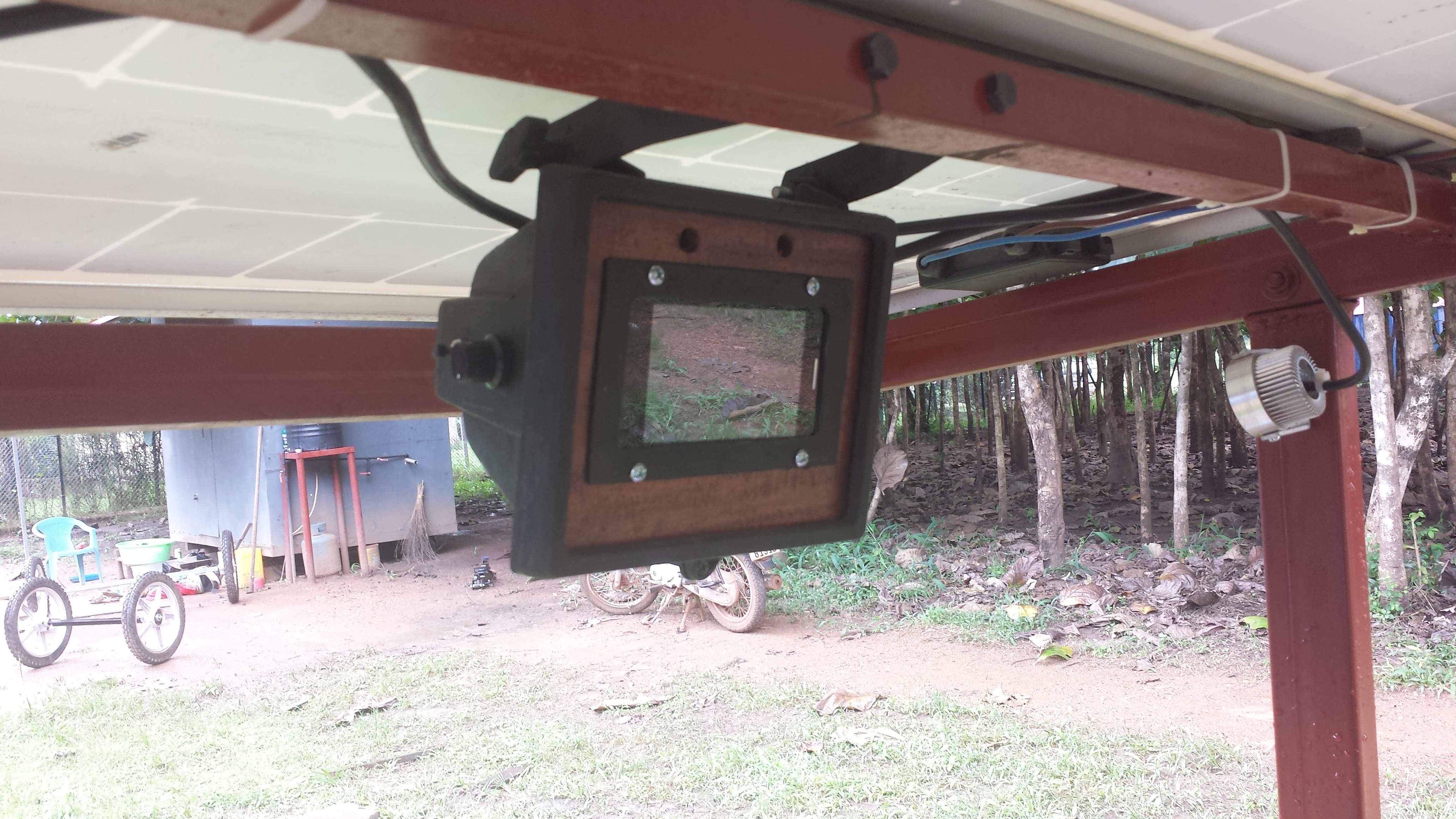
Entertainment System
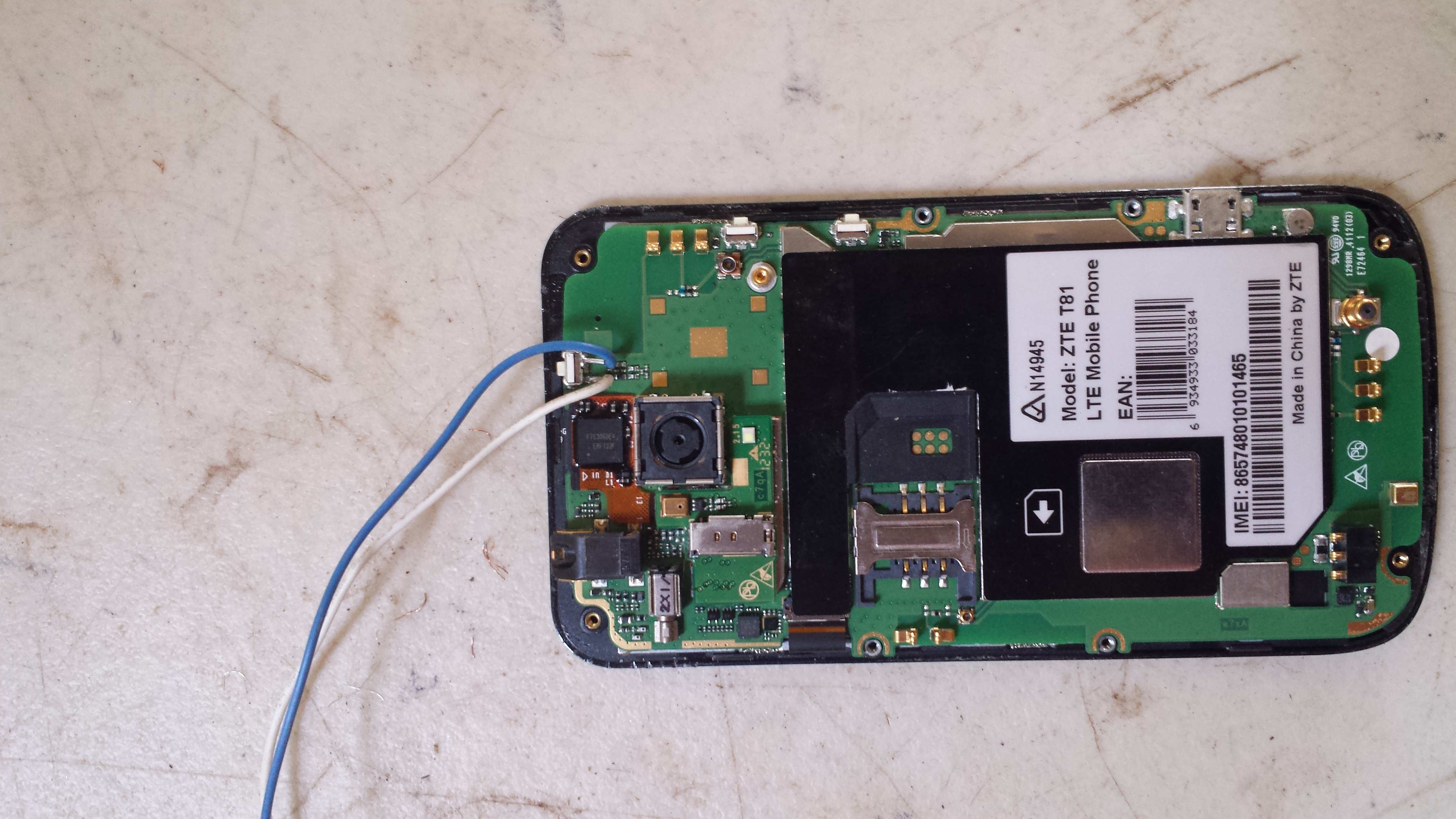
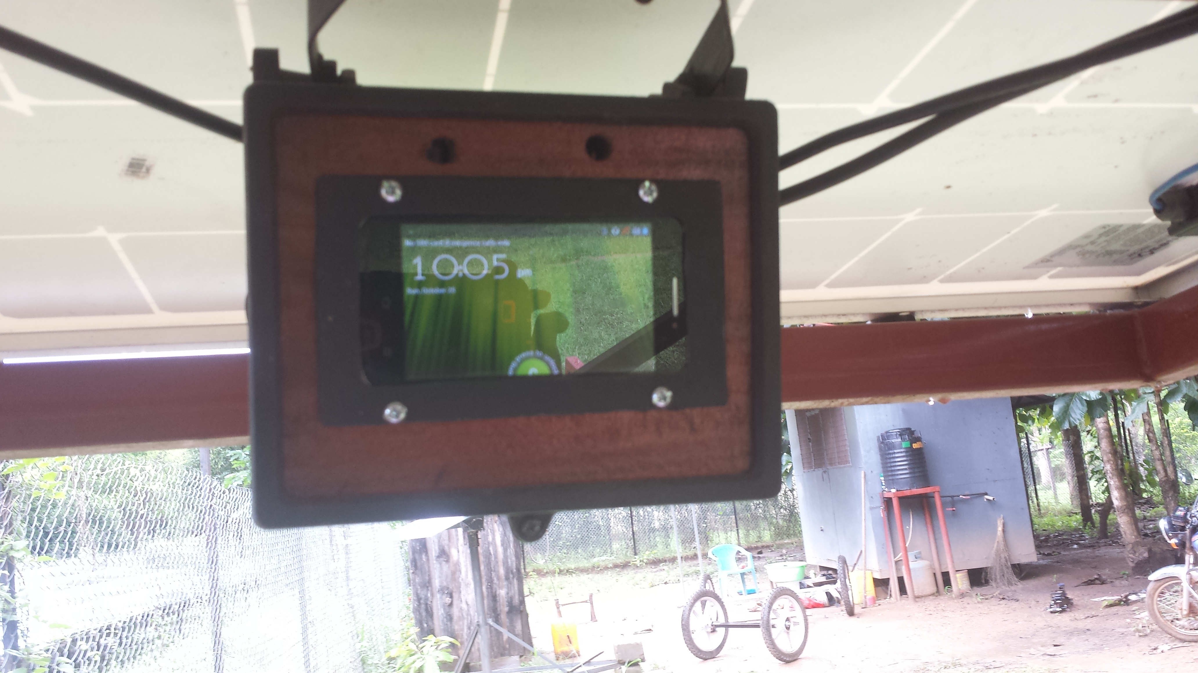
10/26/2015 at 15:23 • 0 commentsWhile this is a utility vehicle, I thought it would be nice to be able to play music, so I decided to add a radio of sorts. When I started looking at options I realized that with the way people go through phones it is pretty easy to find an older model that is just looking for new life. I found an old ZTE T81 Android phone that someone had given me a while back. The phone was locked in Australia, and needed to be back there to be unlocked. While it didn't work as a phone, it is basically a ready built entertainment system.
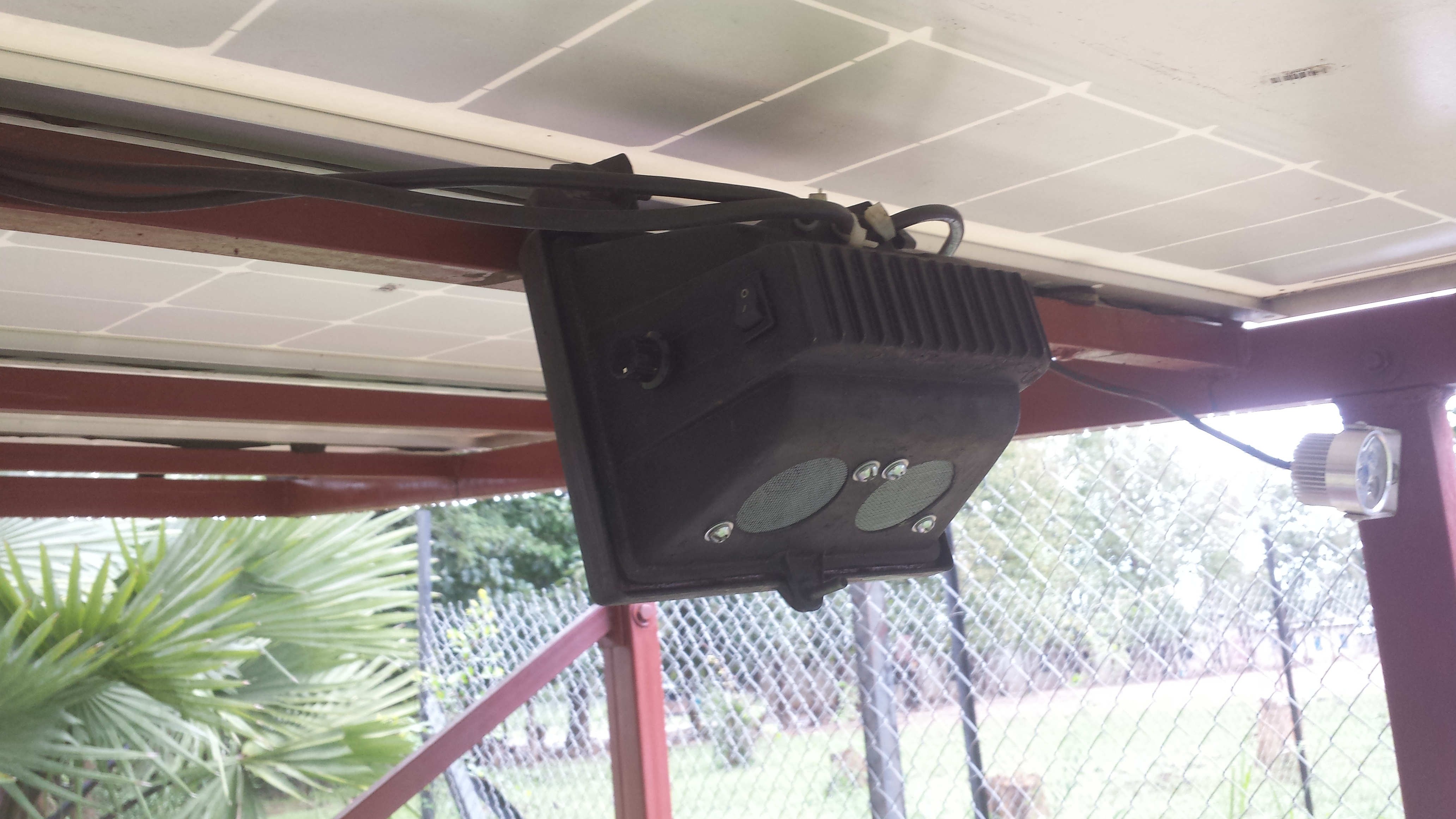
I built an enclosure for it by cutting up an old Halogen work light. The glass was replaced with a piece of mahogany. I cut out a space for the phone using a jig saw. The only real tricky part of the build was adding a external button to turn the screen on. The screen is turned on by a button on the top which was not accessible when it was mounted. I soldered a wire to a momentary switch to simulate a button press.
![]()
The phone is powered by an LM2596HV buck converter wired into a usb chord. A small amplifier and a pair of 3w speakers finish out the enclosure. I also wired in a pair of old led down lights to act as headlights which can be dimmed with a 200k pot. The results turned out pretty nice. I would like to write an android app that connects with the an Arduino via Bluetooth to display system information like battery voltage and current, which would eliminate the current LCD screen.
![]()
![]()
![]()
-
Thoughts on the Hackaday Prize
10/22/2015 at 20:07 • 4 commentsIt is a real honor to have my project selected as a finalist for the 2015 Hackaday Prize. As others have said it would have been incredibly difficult to pick the top ten from the 100 semifinalists. This is especially true when you look at the huge range of projects that were represented. It can't be easy to choose between projects that try to solve such a wide range of problems. One project may be much simpler than another, but it may be done very well. Some people are struggling to come up with answers to problems that are incredibly complex, while others are working to create rock solid products along a much more well tread paths. There is also the added complexity of the huge range of individuals or groups that have taken part. Some projects have been taken on by groups that are working on there projects as professionals, or as a businesses, some as loosely affiliated groups of individuals that only know each other through this contest, some who are working completely by themselves, and everything in between. I don't really know how you would weigh those factors for a competition like this. Is the competition only about the product or idea that comes forth, or is there any consideration for the story of how everything got built.
I am thankful for the competition because without it I would not have finished the vehicle, or at least got it to the point it is now. There are simply way to many other things going on in my life right now. My wife and I are expecting our first child in late December, so my wife just had to fly back home to Australia, because she couldn't fly later in the pregnancy. I am staying in South Sudan for another month to try and set things up for when we come back early next year. We are trying to move to Yida refugee camp on the border to North Sudan to work with the almost 100,000 refugees from the Nuba mountains that live there. Yida happens to be one of the least accessible places on the planet. It is only accessible by road for several months of the year in the dry season, and even then the road is so dangerous it is only traveled by armed convoys. Food is airdropped to the camp, and people get in and out via a dirt airstrip.
I am hoping to travel up to Yida early next week, and take the solar utility vehicle with me. It should be a pretty interesting trip. I am going to load up the SUV along with tools and materials into the back of a heavy truck I have been fixing over the last few weeks. We will drive the truck to the capitol city Juba where I have some contacts with some Russians who fly an old Antinov cargo plane up north. I was given an old shipping container up there that I am hoping to convert into a house. It should be a really good test of the SUV as I will be using it as both transport, and as a power source for tools and welding.
It has definitely not been easy finishing up the vehicle, and there is certainly a number of things I will improve in the future, but I am thankful for the competition for keeping me focused so that I could get this thing done. I hope it can help me to work with people here, and inspire others to try something similar. I haven't finished the building plans yet, but I will have several months once I get back to Australia that I can hopefully use to create a set of plans so that people can build their own. I hope the next month of testing will also show me some areas for improvement. This is obviously a very hardware oriented project, which I think makes it harder to open source. It is easy to release a pcb design, or a piece of code. It is just a mater of git commit, git push. With Hardware a lot more effort needs to be put into creating something that someone can gain meaningful information from. As this project is aimed at people in the developing world it requires more than just 3d files as well. This vehicle has been built using a lot of techniques I learned from people I the developing world, but explaining how to hammer out different metal shapes is not an easy or quick thing to do.
I will be adding a number of updates over the next few days, but this is a project that won't end when the competition does. Regardless of the results, I will be continuing to improve the vehicle. Maybe no one else will make one, but I hope that at the very least this project will demonstrate the viability of solar powered vehicles for certain uses. I hope that others will try to improve on these ideas, ad that we can create something that is of real practical use for people in the developing world.
![]()
I thought this was a pretty funny picture with the Prado in the background ironically with a dead battery.
-
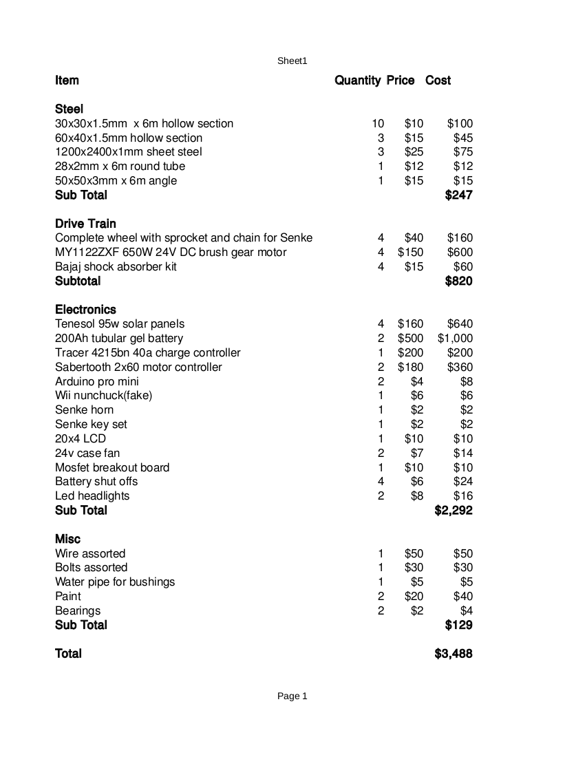
BOM
09/20/2015 at 19:48 • 0 commentsSo here is a general breakdown of the items I have used, and the cost to make a basic vehicle. Total cost is about $3500. I am pretty happy with that number considering there are no fuel costs, and what the vehicle is capable of.
![]()
-
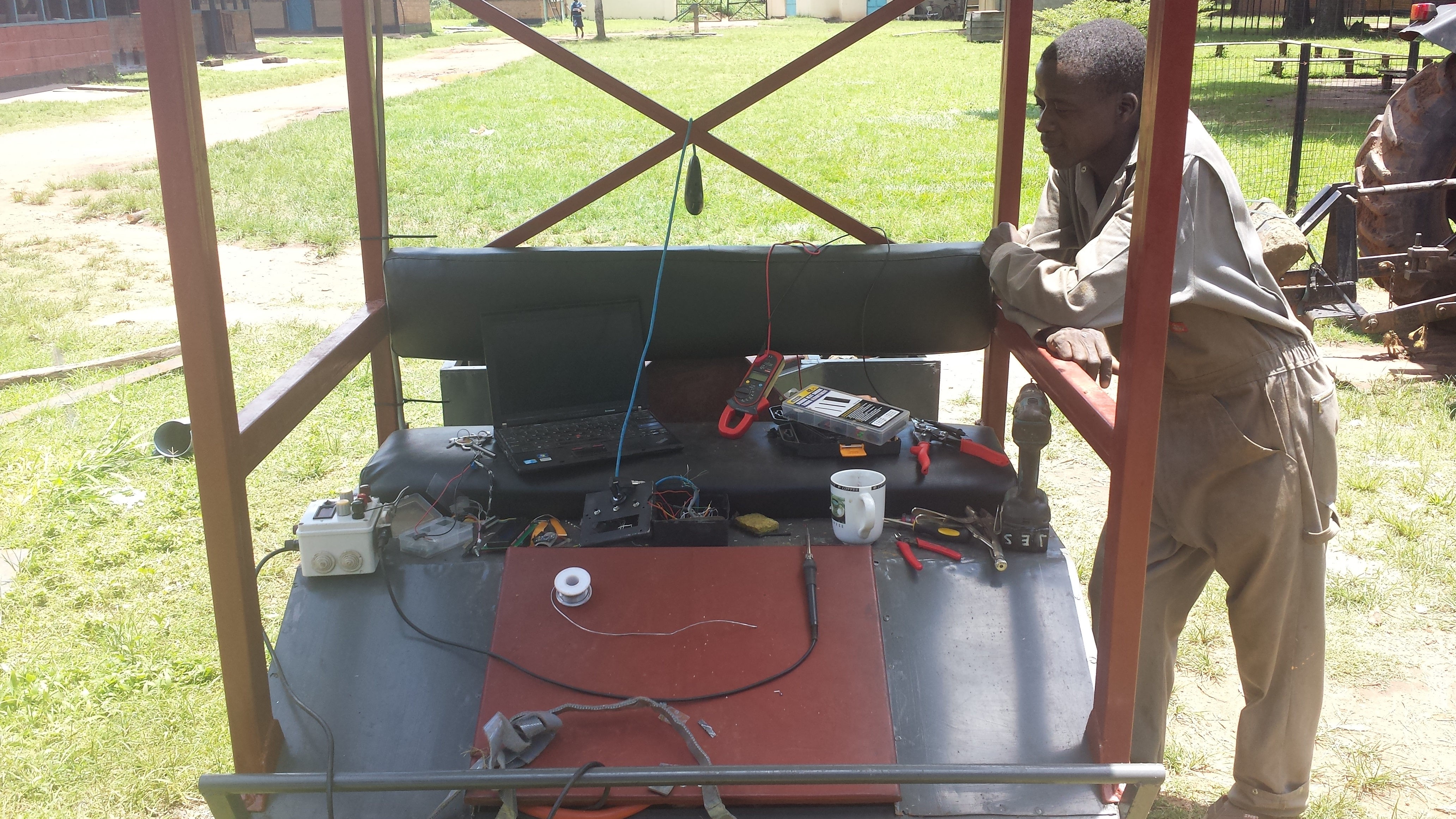
Control System
09/20/2015 at 18:26 • 0 comments![]()
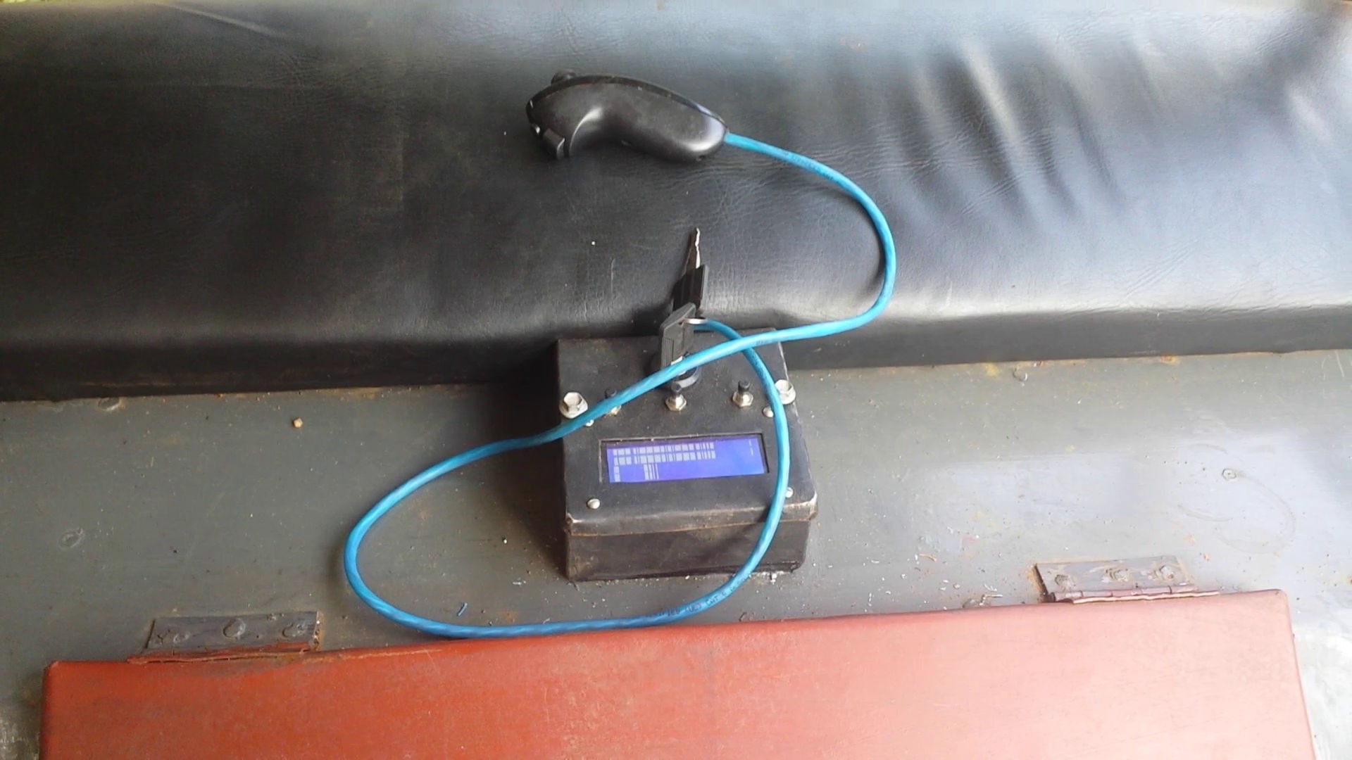
Up to this point I had been running the vehicle with an rc transmitter. It was a simple solution, but certainly not practical in the long run. I wanted a system that was simple and cheap, and could be made as modular as possible so that it could just be bolted on to vehicles made by local people. I decided not to reinvent the wheel when it came to interfaces. I liked the feel of the wii nunchuck, and it gave me the buttons I needed. I already had one out here, for another project, so it was donated for the cause. Unfortunately the cheap ebay knockoff versions are not as 5v tolerant as the Nintendo original, and I seemed to have lost the I2c chip. This wasn't a big deal, because I didn't need the accelerometer, so I rewired it and just read the joystick and buttons with the Arduino.
The Arduino sends control codes to the Sabertooth 2x60 motor controllers via serial packets. The button button will activate a PID control loop when pressed which will control the angle at the pivot point to control turning. Right now there is a pot at the pivot point, but I hope to move to some kind of hall effect based angular position sensor. The other button is for a horn which is turned on with a mosfet.
I wanted to keep the drive as simple as possible to avoid anything weird. All the other non critical components are controlled by a second Arduino. This Arduino connects to the sensors which include 6 ds18b20 temperature probes to measure temperature for all motors and batteries, an 3 Allegro Microsystems ACS758 current sensors. It controls output to lights, two case fans, and accessories via mosfets. Its main function is to display all of this information on a 20 x 4 LCD screen, and set parameters for things like temperature alarms, and fan on temps.
![]()
![]()
The programs are still works in progress, but they are functional. The code in its current state is available in the github repository along with pinouts and my wiring layout.
Light Electric Utility Vehicle
A rugged low-cost solar electric utility vehicle platform for the developing world