Chris Low
-
Center Pivot
09/20/2015 at 08:01 • 0 commentsI chose to build an articulating vehicle because they are very efficient when it comes to turning, and require very little power to turn. It also makes adding 4wd fairly trivial when it comes to an electric drive train like mine. A pivot that only moves in one plane however concentrates a lot of stresses when the vehicle goes over rough terrain. A universal joint that allows complete freedom of movement would simply cause the vehicle to drop at the hinge point. What we need is something that acts as a hinge in one direction and can rotate on one side.
Here is a quick video of what I am talking about
To make this system work well has been a bit of a challenge, because I don't have access to any specialty equipment, and I am trying to make something that is reproducible by local people here in South Sudan.
![]()
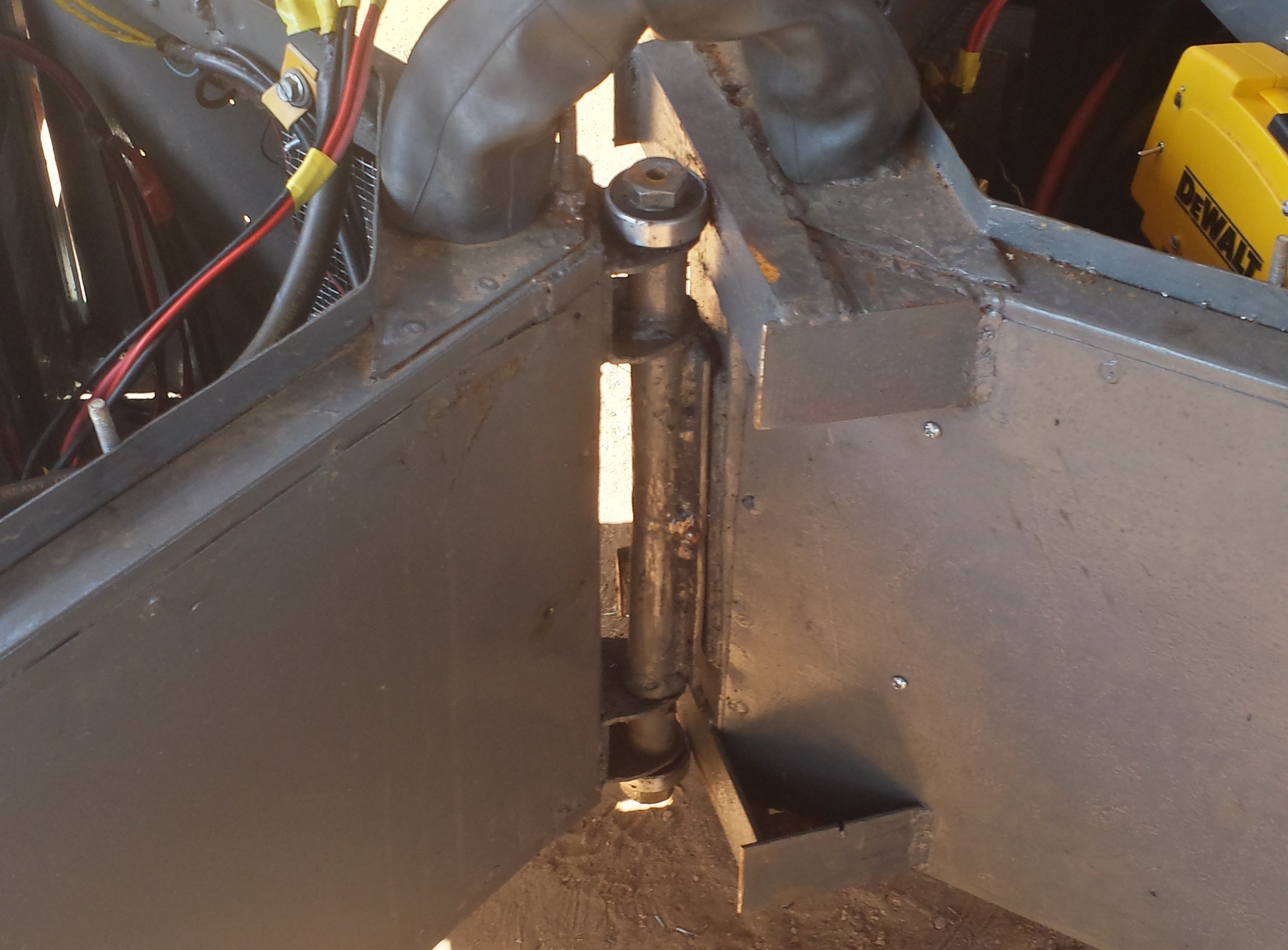
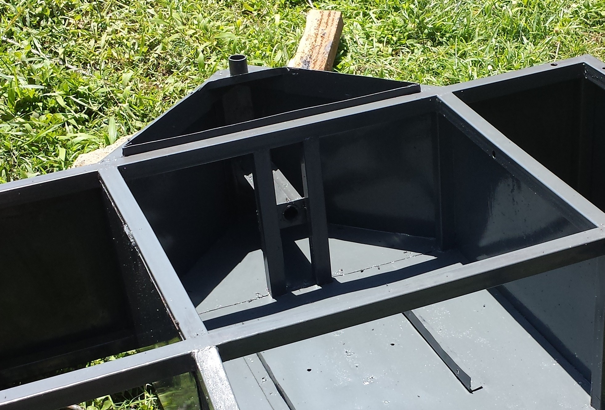
What I have come up with is a hinge that rotates at the center, but the moment force actually transfers from one frame to another through bearing at the top and bottom. This makes the system very strong. I can get up and jump on the pivot point and notice no real deflection.
parts the make up the hinge are normal round tube. This is not actually round inside as it has a welded seam, so I use 1/2" water pipe as a bushing. It seams to work quite well, and when it wears out can be replaced for almost no cost.
![]()
The rotating part was made in a similar way. Two pieces of angle were cut to make a tube the right size to hold a larger water pipe which allows to metal pipe inside to rotate. a welded stud at the end allows a nut to lock the piece from pulling out.
-
Solar Panels
09/20/2015 at 06:58 • 0 comments![]()
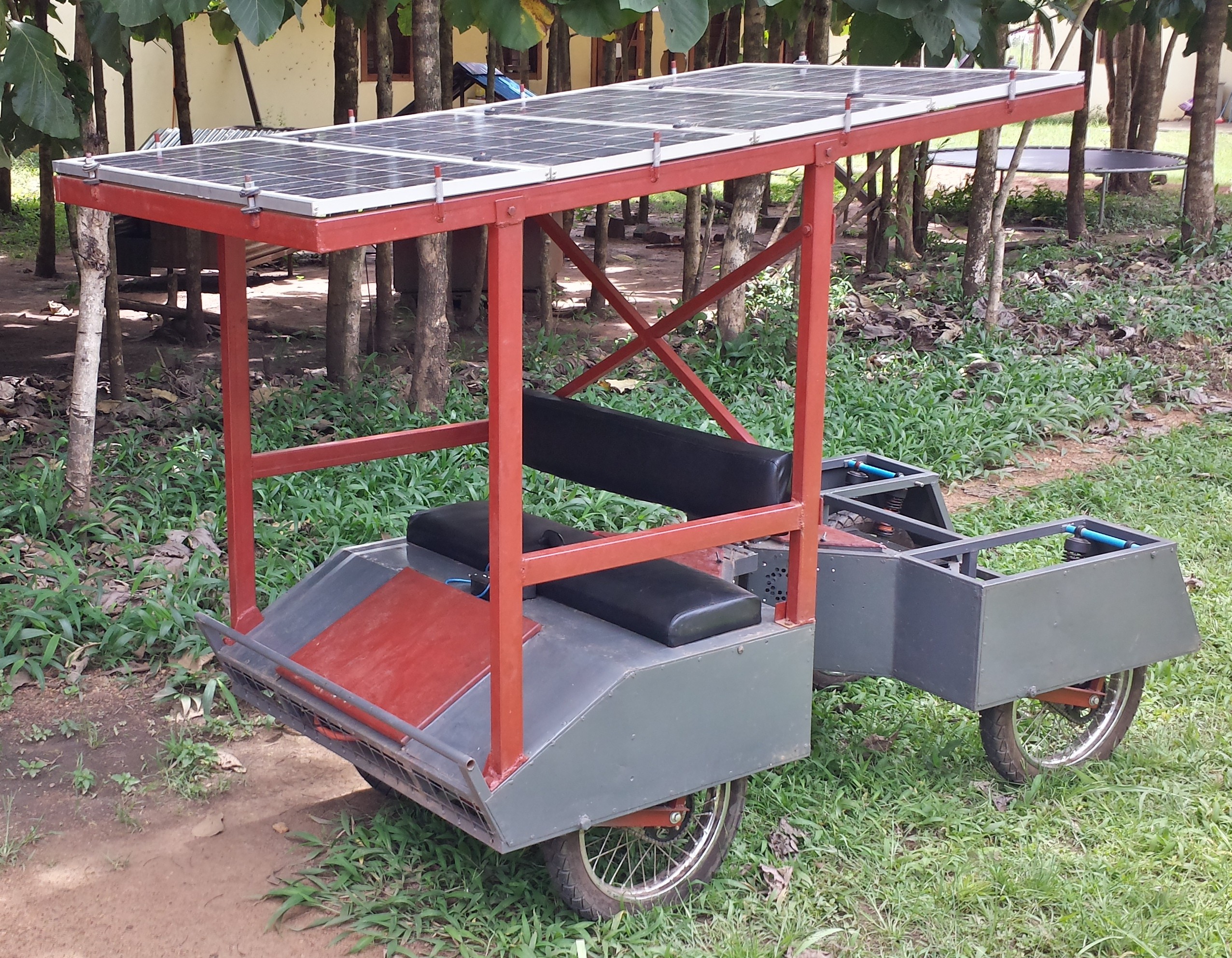
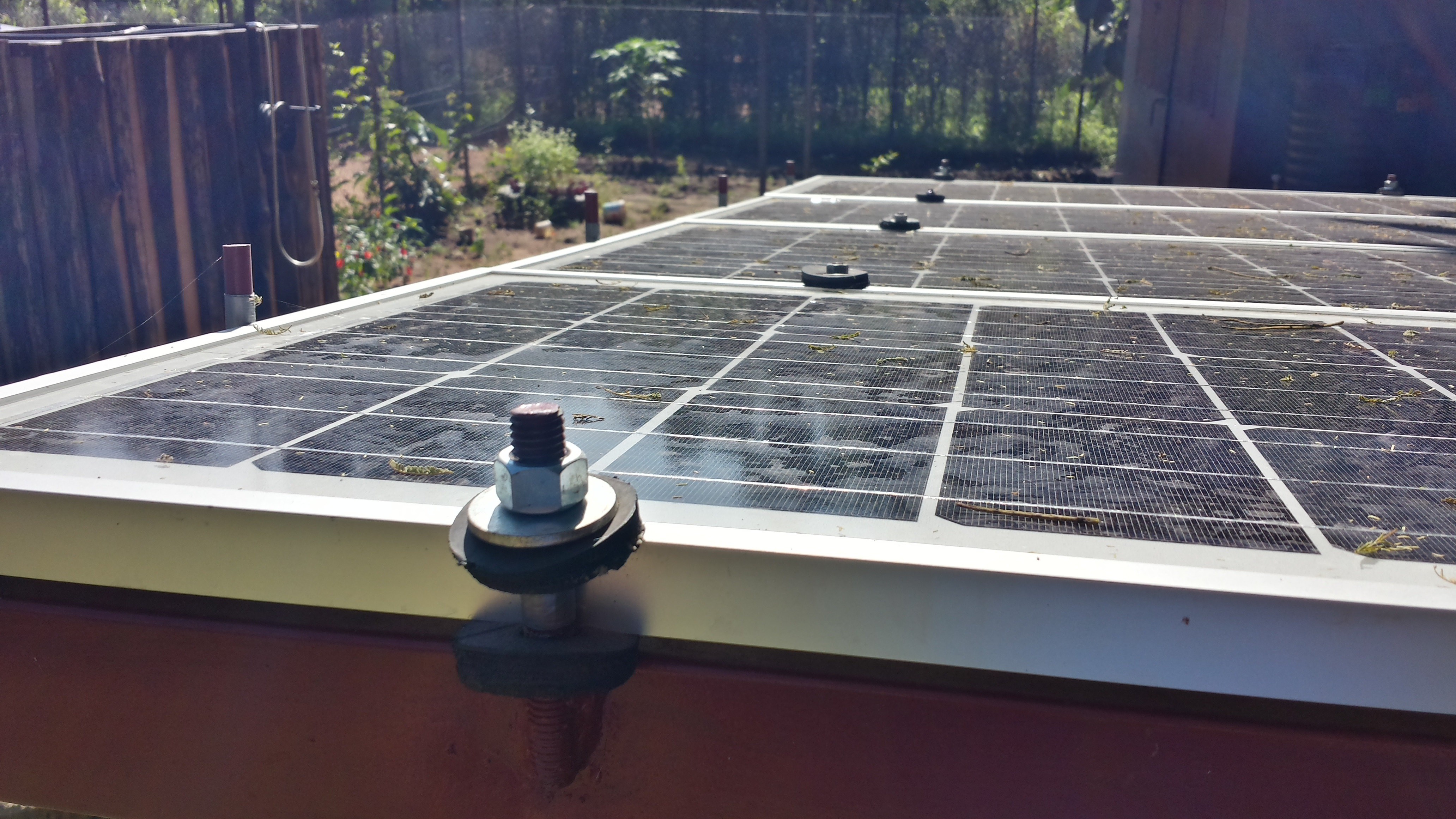
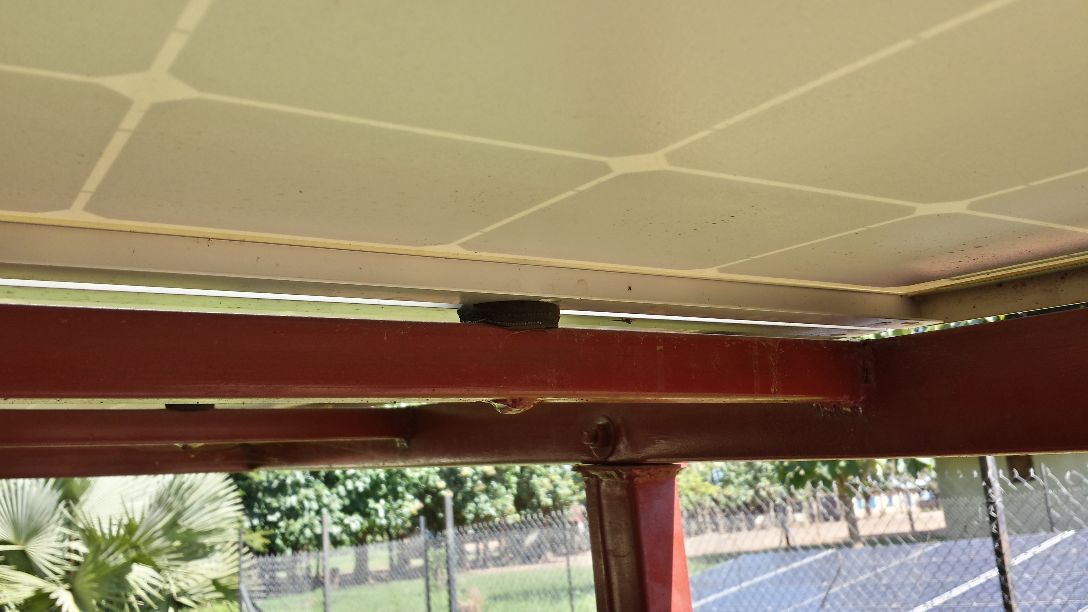
As this is a solar powered vehicle I should probably say something about the solar panels. The panels I am using are 95 watt Tenesol 95 watt monocrystaline panels. Each of the 4 panels measure 556mm x 1231mm. This has been the determining factor in the width of the vehicle. I wanted to make sure the bumps from the vehicle didn't transfer directly to the panels, so I wanted to avoid directly bolting the panels on to the frame. Instead I built shock mounts by cutting thick rubber washers from old tires. The washers then sandwich the rail on the panel. This keeps the panel in place, but still allows the frame to flex a bit to avoid shattering.
![]()
![]()
The charge controller is an EP Solar 4215bn 40 amp mppt charge controller. I really like this controller. It has a great heat sink, and a fairly well understood communication protocol that can be captured by an Arduino.
It sits in the rear section of the front half. I mounted a 24v case fan across from the controller which turns on when the compartment reaches a set temperature which can be adjusted from the front control panel.
-
From Fence Posts to Suspension Arms
08/31/2015 at 18:45 • 0 commentsI wish I had a complete plan before I started this project, but as with any project like this things are improved along the way. Some things work, and some things don't. I knew that a wanted to create a different suspension system for the second version, but unfortunately my first attempt left me pretty unsatisfied. I now have a system that I really like, and though time consuming is relatively easy to build.
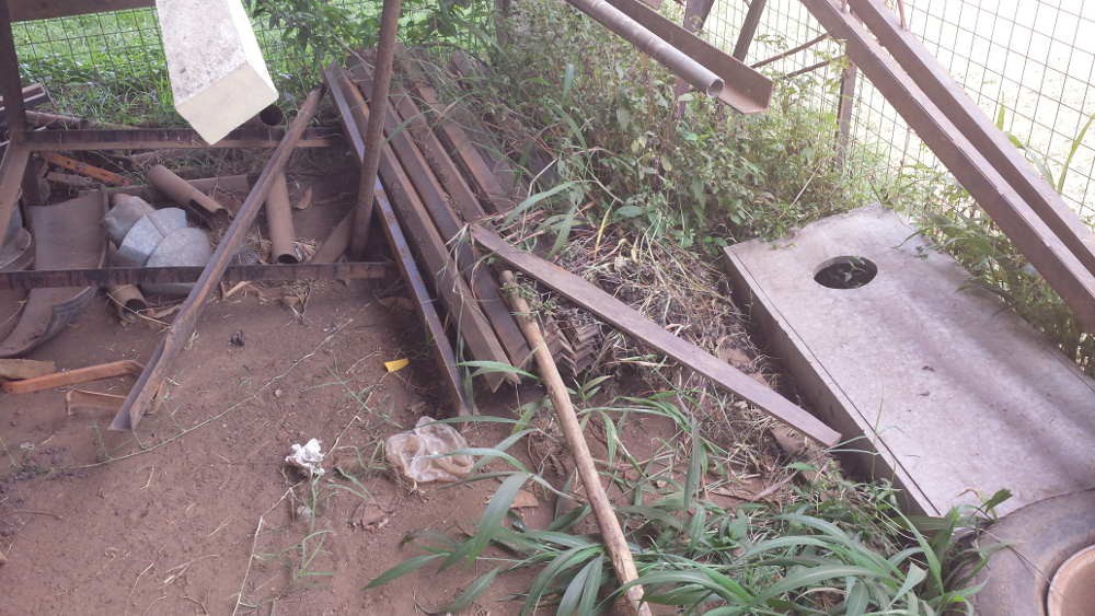
The arms start out as old fence post which were made from 50x50x3mm angle.
![]()
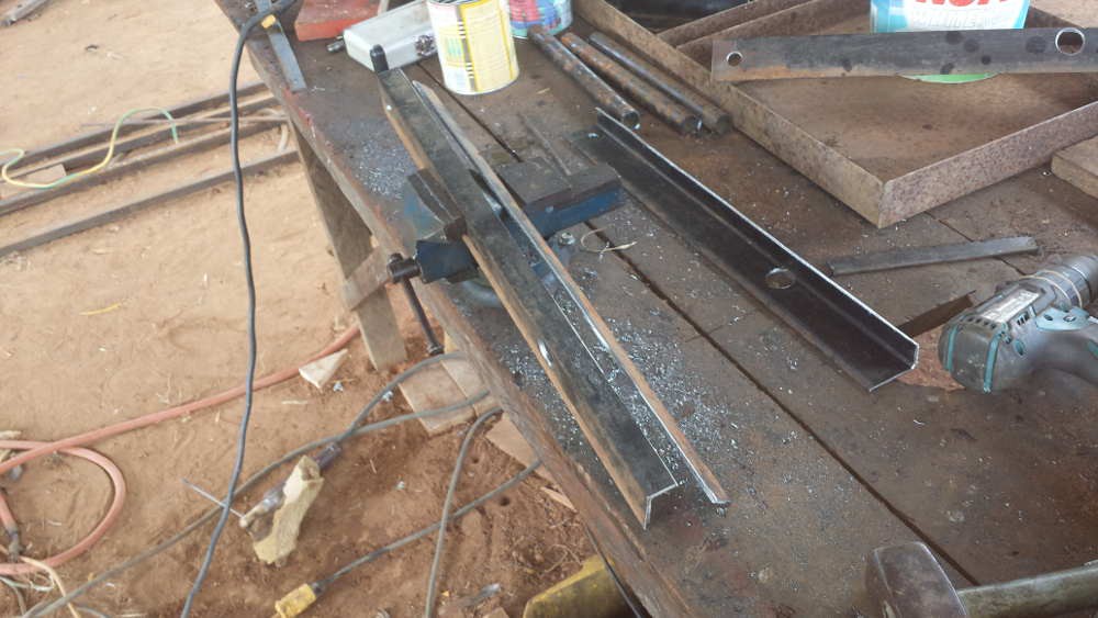
These were then split along the top to make the top 25mm for clearance in the frame. I split them by scoring a line with an angle grinder and then using a sawzall with a metal cutting blade. Holes were then drilled to allow for the wheels to be bolted as well as the pipe which holds the shaft that attaches the assembly to the frame.
![]()
![]()
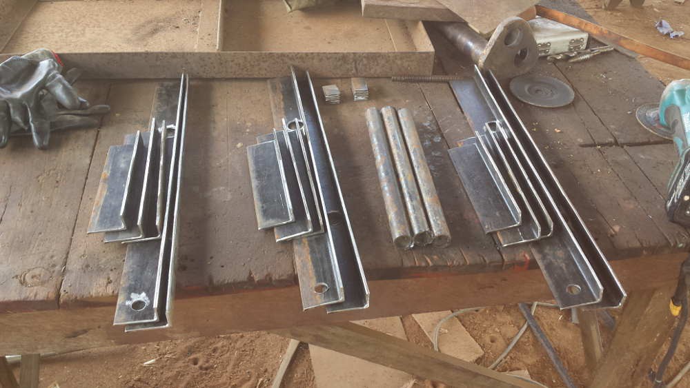
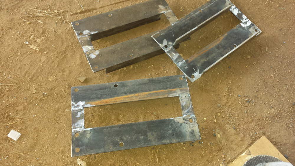
Pieces cut for assembly
![]()
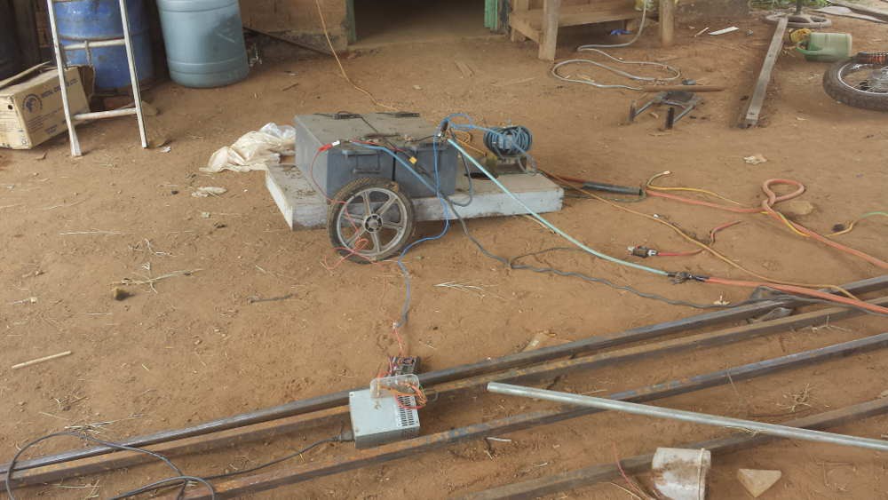
Welding with my trusty batteries and arc stabilizer.
![]()
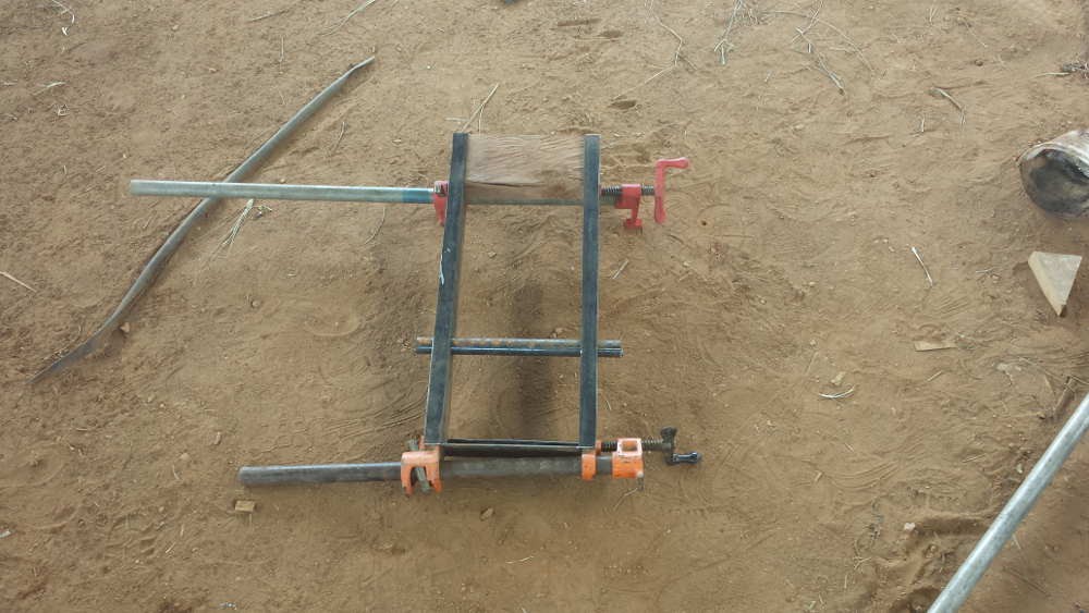
Clamping everything together for welding.
![]()
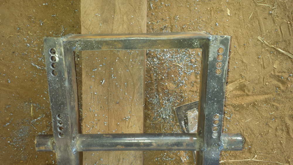
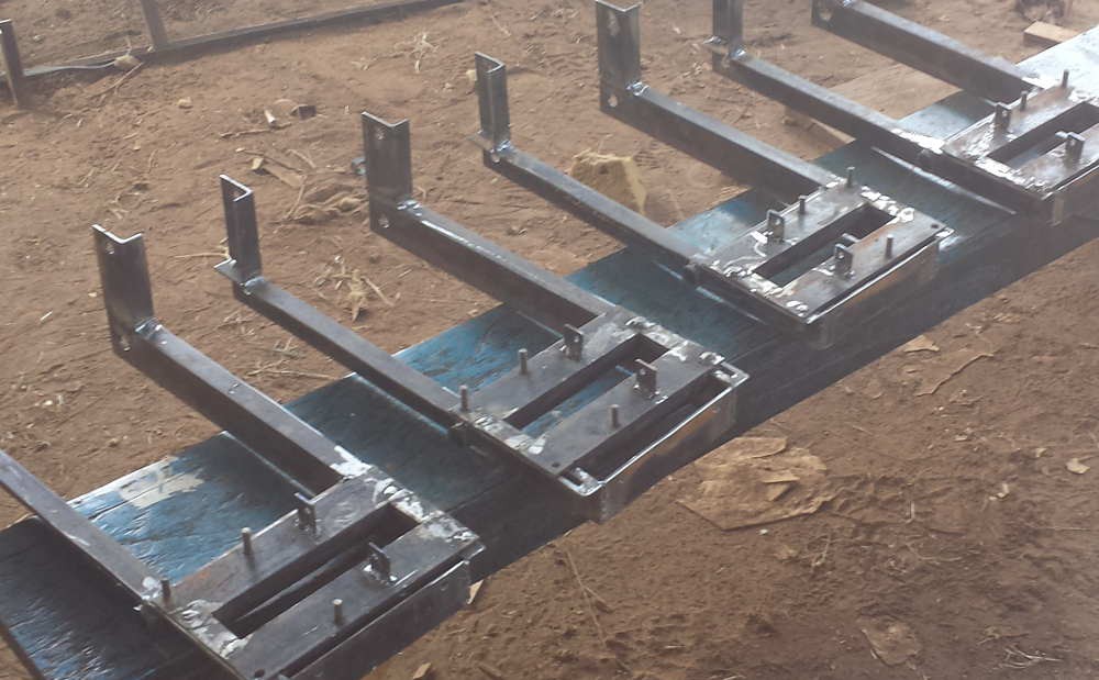
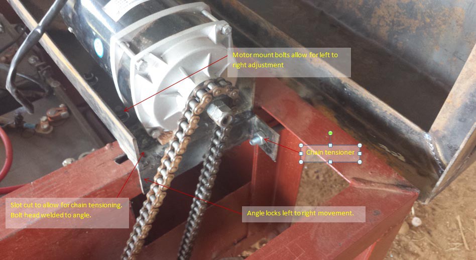
I needed another piece that could sit on top of the arm and hold the motors. This piece needed to be able to slide in order to tension the chain. This was made using the same 50mmx50mm stock.
![]()
To allow the motor mount to slide I had to make slots in the suspension. I started by drilling a series of holes, and then cutting them out with a small grinding disk.
![]()
I added bolts and mounts to hold the motor and to secure the assembly to the arm. I also added mounts to attach the shock absorbers.
![]()
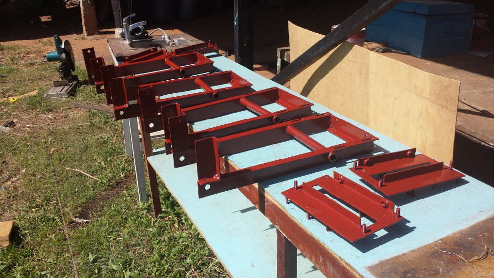
Then everything got a couple of coats of red oxide paint.
![]()
After the paint dried everything was reassembled.
![]()
Close up view.
Quick video of how the tensioning system works.
-
Version 2.0 at my local Hackerspace
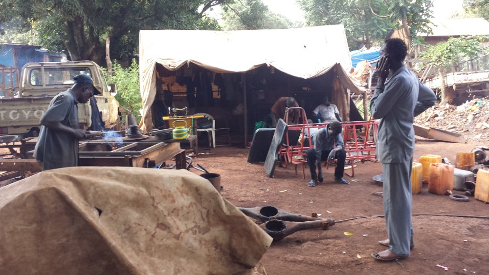
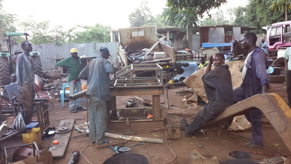
07/26/2015 at 06:51 • 0 comments![]()
Anwar's welding shop
While it may not be called a hacker/maker space here in South Sudan, the idea of a collaborative work space where people share tools and work on different projects is nothing new. I have always loved working in African workshops, and I think they really embody the ideas of the hardware hackers. I have seen so many machines resurrected from the dead, and hacked together out here. One of my best friends out here runs a shop where they will work on everything from repairing engines to building sawdust fueled bread ovens. The first time I met Anwar who runs the shop I was looking for a pulley to connect to the drive shaft of a small tuk tuk like vehicle that I wanted to have power a small table saw (this worked but it was ridiculously dangerous.) He was busy trying to build a material elevator from a car axle for a nearby construction site. We became fast friends. I often go to his shop to have tea and discuss ides and work together. The shop itself is open air, and could easily be confused for a junk yard, but the things produced and fixed there are really impressive. Most of the things they make are made from scrap metal they reclaim from destroyed vehicles. This they weld with welders which they hand-wind themselves. The only other tools in the shop are a 9” angle grinder, a few wrenches and hammers they have welded from various drive shafts.
![]()
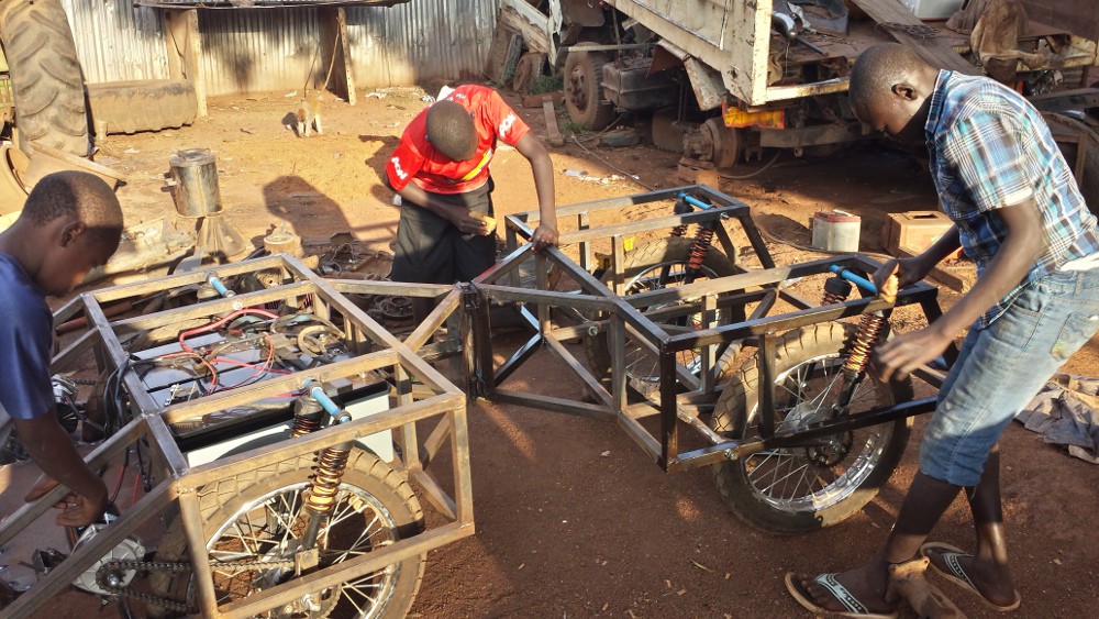
Working on the new frame
I have been talking with these guys a lot about this project, and we have been sharing ideas. I was excited for the second version of the utility vehicle to build it with these guys. I have been redesigning the body of the vehicle for quite a while so that it included such luxury items as suspension, and a place for people to sit. I have been thinking a lot about suspension, and how to source something locally which I can also find on a continuous basis. I've come back to the mass produced motorcycles as a nice cheap source of coil over shock suspension. I can get them for about $15 a pair. I am trying out a trailing arm suspension system, that is really similar to the back end of a motorcycle. I want to make sure nothing is too complicated to build, because I am hoping that welding shops like this one are the places where these vehicles could be produced.
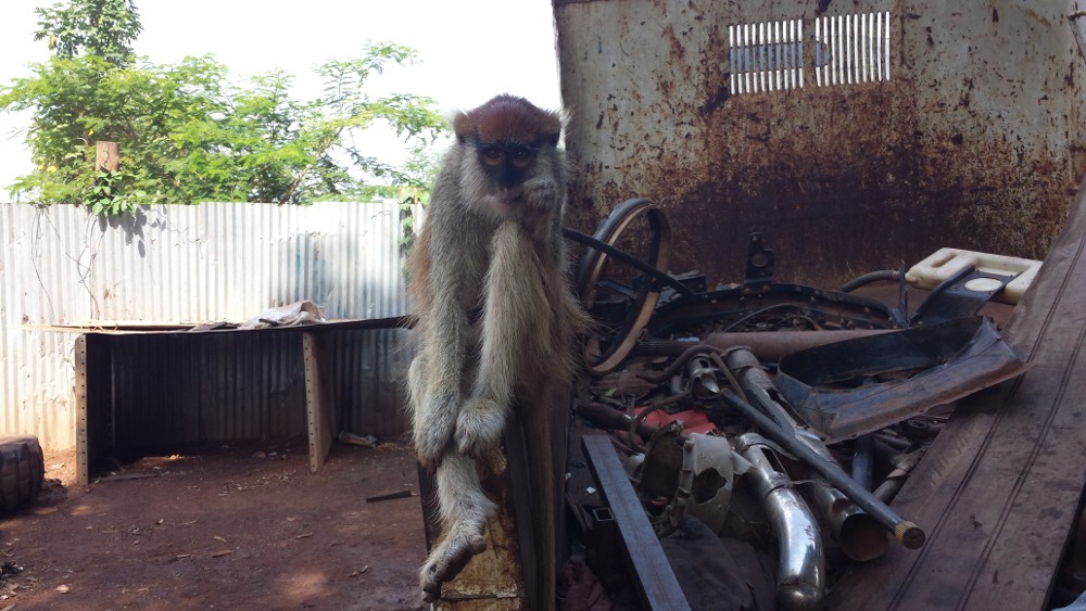
![]()
The mascot of the welding shop
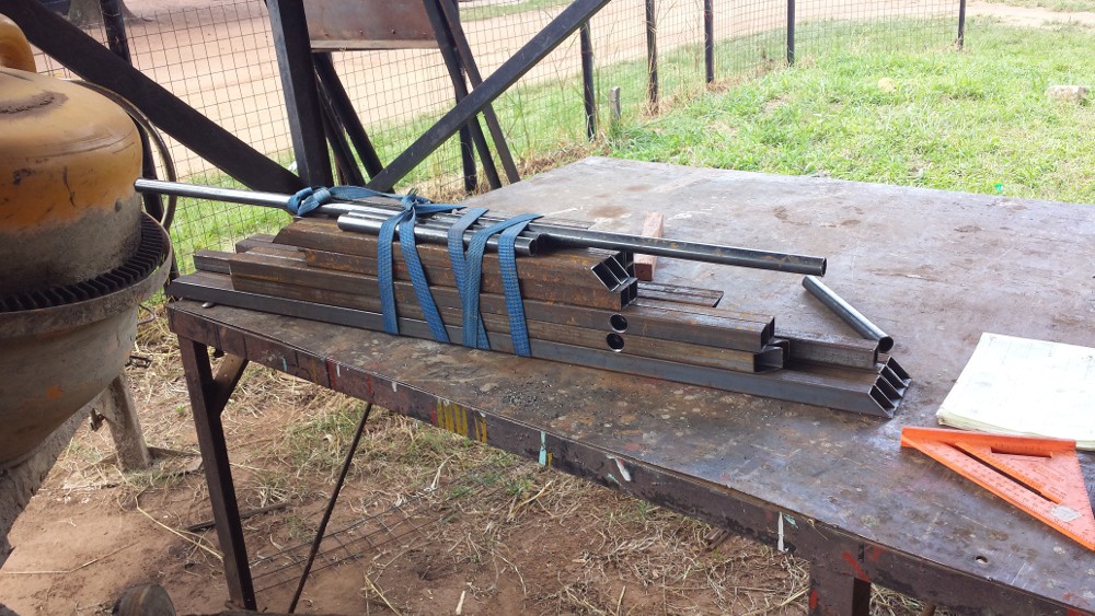
I used sketchup to model the frame. While it is not a great tool some applications, I find it great for modeling with standard steel sections. It let me confirm clearances for motors and batteries. I cut all the frame elements, and took them to Anwar's shop to assemble them.
![]()
Pieces for the front section ready for assembly
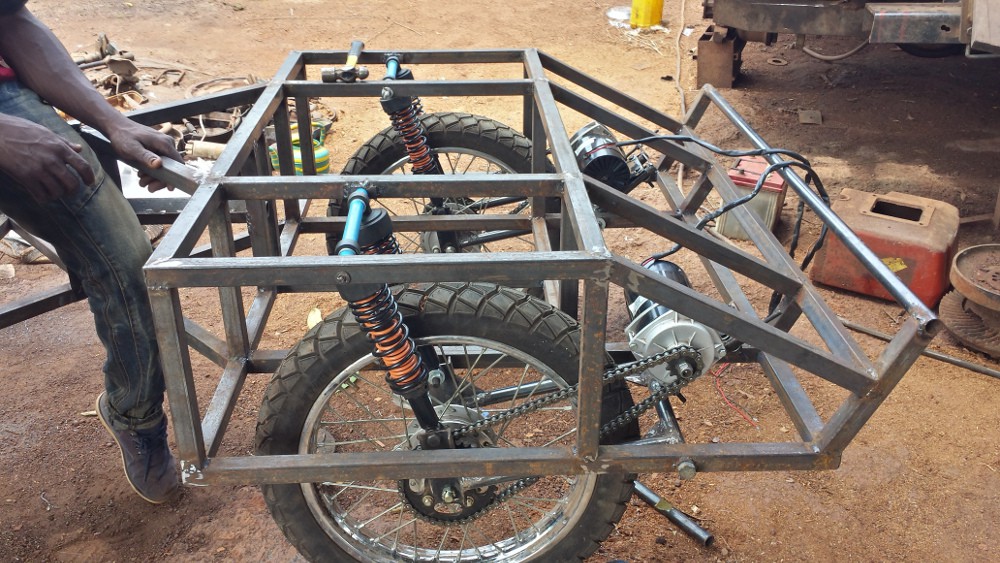
Everything was designed to be assembled easily. I assembled the frame over the course of a few days, but I think I could do it in one day if I was set up. I am really trying to not use anything specialized, and only standard steel sections. Rolled sections have a welded seam which makes them not really useful for bushings, however I've found that 1/2” water pipe with a slit cut in it slots inside the pipe I am using and makes a great low friction bushing for the suspension.
![]()
I will try to update with more detail, but you can get a general idea from the photo of how the suspension works. The motors have to be mounted on the arms so that chain tension remains constant.
![]()
We finished assembly of the frame, and took a quick test drive through town, which got a lot attention in town.
![]()
-
Steering
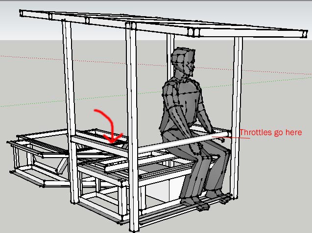
06/28/2015 at 17:47 • 0 commentsSo I have been playing around with this thing, and it has been doing pretty well, but it is definitely time to think about a permanent steering system. The remote I have been using has been great for proof of concept, but if you have ever tried to drive something with a remote while you were sitting on it you know it is a good way to fall off. With the lack of engine, it is nice to be able to get in from the front, but when you are driving you really need something to hold on to. I’ve been thinking of a flip down bar that allows both the passenger and driver to hold on, then flip up so that people can get out. See photo.
![]()
I started thinking about what is the most intuitive way to drive a vehicle with differential drive steering like this. A joystick makes sense, but doesn’t really allow one to hold on well when you are going over rough terrain. I decided I wanted to try out dual twist throttles. Like what you have as a motorcycle accelerator. Unfortunately normal motorcycle parts wouldn’t work here because I want a throttle that springs to the center position to allow for movement in both forward and reverse. I decided to custom make a throttle set up that would be in line with the grab bar in the front. I also decided to put an lcd in the middle to give a live display of battery voltage, motor current, solar power coming in and maybe a few other things.
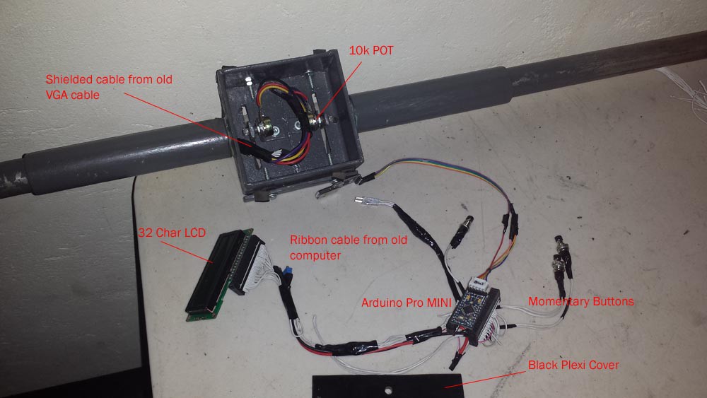
![]()
The throttle assembly is all steel. The grips are a slightly larger diameter pipe that slides nicely over the grab bar. The throttles turn a pair of 10k pots which are then read by the atmega328p which will look at this plus the readings from a pair of allegro ACS758 200a hall effect current sensors to determine the pwm to the motor controller.
The display is just a simple 32 character LCD running with another Arduino pro mini. I will include several buttons to change some settings and also control horn and lights.
![]()
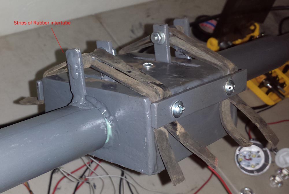
Probably the hardest part was figuring out the spring return to center. At the moment I am using strips of rubber from an old truck inter-tube. It gives a nice strong feel.
I am looking forward to mounting this thing to try it out on the vehicle.
-
New Video
06/07/2015 at 10:10 • 0 commentsJust a quick compilation of testing videos.
-
Refining Things
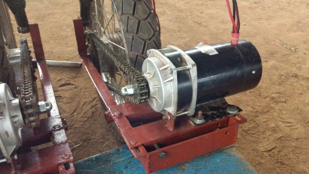
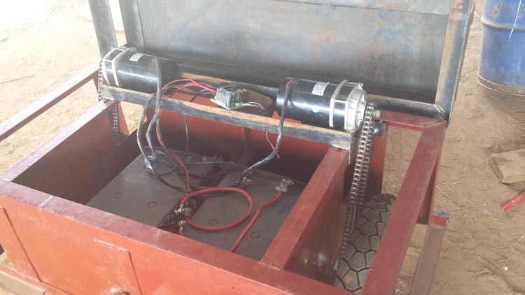
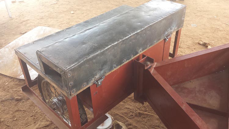
05/23/2015 at 15:34 • 0 commentsWhile I have generally been pretty happy with the vehicle so far, there are a number of areas I would like to improve on. In my mind the current vehicle is more of a test bed to see what will work and what won't for the next version. I already have a pretty significant redesign done on the computer, but I would like to keep testing the current version to find more weak points. One area I had to change was the motor mounts. While they fit nicely in the original frame, mounting them upside-down as I originally had them put too much flex in the drivetrain, and caused them to slip. Instead I have mounted them on top of the frame in a way that allows me to tension them by a bolt. See photos.
![]()
![]()
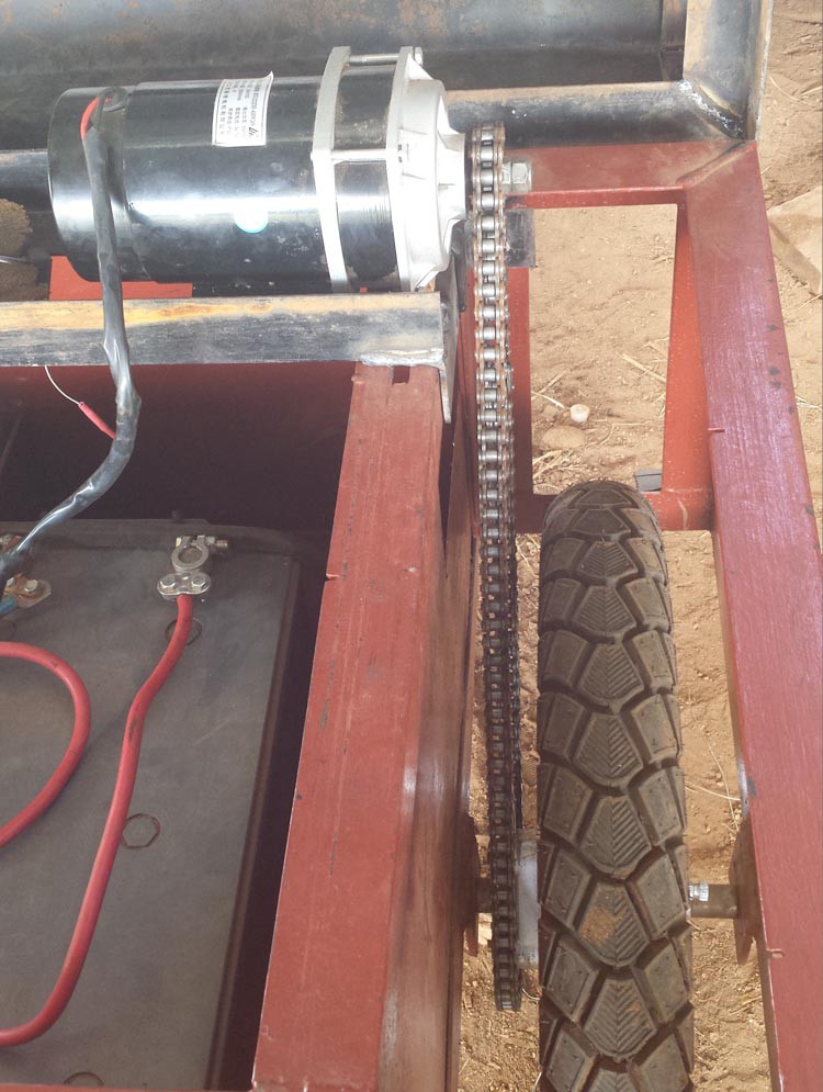
This view shows the connection to the wheel. Because of the built in planetary gearbox on the motor I can eliminate multi-stage gear reduction which greatly simplifies things.
Amazing how well it works for the moment considering how few components there are.![]()
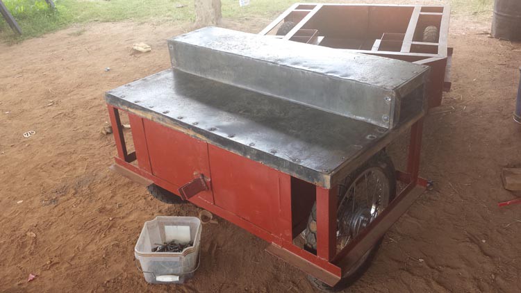
Put on a cover/place where the seats will mount. I am hoping that I can eventually put in a shelf so that this will also act as a locking toolbox.![]()
The lid flips up from two hinges on the back.![]()
Another issue I am having is a bit more serious as I am hitting the current limit for the controller which is 60a per side continuous and 120a peak. Admittedly I am doing some torture testing as I am hitting this while trying to drive over big piles of loose sand, but it will continue to be an issue so I am looking at other options. The sabertooth 2x60 has built in over-current protection so I get a series of jolts when I am pulling between the 60a continuous and 120a 1 second peak. I think I need to find another controller. Which leads me to my question for everyone.
Does anyone have any experience with the OSMC open source motor controller? At 160a continuous and 300a peak it looks good on paper, but I feel like it is thermally questionable. Any newer designs out there with similar specs?
-
Movement
05/15/2015 at 18:22 • 0 commentsIt has been really busy out here in South Sudan, so I only get to work on the utility vehicle on random occasions. I am long overdue for an update as things have progressed relatively well. I haven't done a great job of documenting each step, but I will be publishing plans once I work some of the kinks out. Here is a video of where things are now. I currently only have the front two motors hooked up, and I am controlling it from a normal 6 channel rc transmitter. I haven't made any adjustments yet to the stock settings yet, and the controls are very touchy. Steering is all done via differential motor control. The pivot point is just a pinned hinge connection. At the moment I am just using the skid steer setting on the sabertooth to control steering.
I was really impressed with the amount of power, and the gearing ratios seems about right. I am not sure if I can get away with keeping things really simple and running the receiver directly into the sabertooth motor controller like I have now, or if I have problems running a potentiometer at the pivot point to give the angle and creating a pid program that keeps the vehicle tracking properly. I will have to see what happens when I add the rear motors.
I am currently using two 230ah agm batteries that I pulled out a solar bank because they didn't match the other batteries. I think they have been pretty abused, so I don't hold high hopes that these will work well long-term. the only other electrical components at this point are a resettable fuse and a keyed battery disconnect.
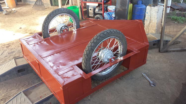
I've skinned the frame with 1mm sheet metal and slapped some paint on it. The next major structure will be a dumping bed, and covers over the battery compartment. I am also in the process of sourcing solar panels, which I hope to use to make a solar canopy later on. This will be both for shade/rain as well as charging. I am hoping to get at least 400 watts of panels preferably closer to 600 watts. I think this should be enough for a utility vehicle which spend most of it's time stationary.
I've taken very few photos, but here are a couple from my phone
![]()
The underside. The really nice thing about this configuration is that I don't need any axles, which means I get great ground clearance. I actually have better ground clearance than on our land cruiser.
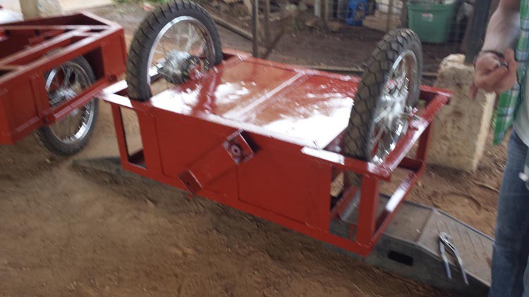
![]()
The body panels are just 1mm sheet metal I can buy locally and cheaply. I attached them to the 50x50mm angle with an arc welder. It is too thin to weld from the edge, so I weld a spot about 15mm from the edge. I let the rod burn through then form a puddle which acts like a rivet. It is amazingly strong and very quick.
![]()
Poor quality photo, but this show how the two halves are connected. The back is pinned through the holes, which allows for movement in two directions.
-
Sourcing Components
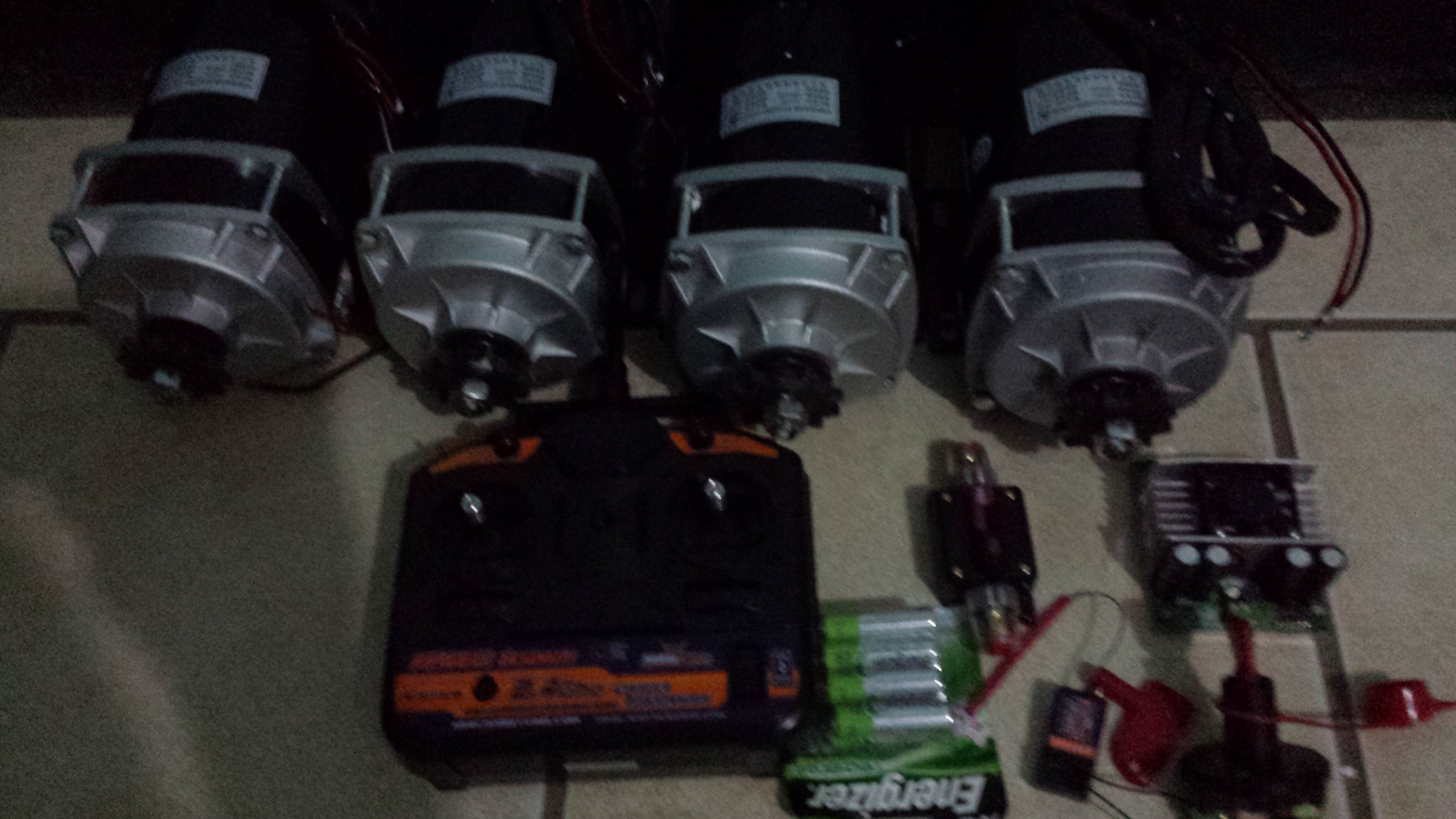
04/15/2015 at 17:22 • 0 commentsGetting components for this project presents a really interesting challenge. I am sure a lot of Hackaday faithful are with me in enjoying the fruits of our interconnected globalized marketplace. Unfortunately the reach of globalization has its limits. South Sudan has no postal system, nor do any of the major shipping companies work here that I am aware of. Other East African countries have access to global shipping, but at quite a cost. Of course at the heart of any EV build is the electric motors. I have chosen to use four Chinese Unite MY1122ZXF 650W 24V DC brush geared motors for the simplicity of the built in planetary gear reduction. The motors are cheap and fairly light, but with four of them weight is still over 30kg which puts shipping cost over the cost of the motor. I sourced them on Aliexpress for just under $300 for the 4 motors and $350 for DHL shipping to Uganda. From Kampala, Uganda up to Yei, South Sudan where I am working one has to be a bit more creative. I lucked out and was able to get the motors brought up in a truck owned by one of the local churches. They owed me a favor because I have been fixing their bulldozer. The Bishop has a lot of pull around here, and so his truck clears customs fairly easily. If I couldn't use his truck I probably would have had to have the motors put on a passenger bus, and then have one of the local taxis carry it across the border with their passengers. This is the way I typically get replacement parts for machinery.
I was able to get most of the control circuitry shipped to someone who lives in the US who was coming out for a short-term visit. He then carried it out to me in his checked bag, and brought it in a small airplane.
Needless to say one needs to have some pre-planing out here, as getting things fast is next to impossible. The motors just arrived today with only a small dent in one of the fan casings. Unfortunately I won't get to play with the for a while as my wife and I are heading to Yida refugee camp for a week, but I am looking forward to some testing soon.
![]()
Light Electric Utility Vehicle
A rugged low-cost solar electric utility vehicle platform for the developing world