Frank Vigilante
-
Smart Garden Mini
05/13/2015 at 09:44 • 0 commentsIf The Smart Garden is the platform for an IoT gardening system parent, then it needs some children to receive its knowledge. Below is the Smart Garden Mini. I will create a new project to track the Mini so as to avoid confusion.
![]() - Explanation of its functions will also be provided at the new project page:
- Explanation of its functions will also be provided at the new project page: -
An overly expensive and redundant PCB
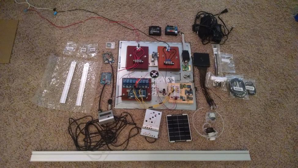
04/24/2015 at 22:27 • 0 commentsBecause The Smart Garden is being built as a platform for future robotic gardening systems, I am going to throw cost minimization out the window for the first PCB. It will include many components that serve a redundant purpose. From this platform, I will then be able to reduce the PCB down to a more efficient design. So where do I even begin? In order to answer this question, I decided to gather a good portion of the electronics, and begin to map out my plan for the first board.
![]()
This log will discuss which components shown above will be incorporated into the first PCB, and why....
1. Power supply - The first PCB will take in 12V. It will likely have both, a barrel jack. and terminals so I can alternate between power adapters and solar panel supply (notice the solar charge controller and 12V adapters in the picture).
2. Power Regulation - The PCB will regulate down to 5V and 3.3V. In the picture, you can see a 7805 creating a 5V supply in the breadboard in the middle bottom of the motherboard. The broadboard in the middle top has a 3.3V regulator (but i previously harvested the capacitors). For both of these, I will use really nice heat sinks and capacitors.
3. Relays - I am going to keep using relays because I want to preserve the ability to not only shrink the smart garden design, but also scale it up big! The first PCB will probably have a bank of 14-16 relays.
4. Micro-controller - I see no reason not to put a ATmega2560 in the first PCB. It should be able to handle everything that I want to do.
5. Communication - This is where I am going to get really redundant with the first PCB. In the picture you can see a CC3000, a HC-04 BT module, a ESP8266-12x2, and a RF transmitter/receiver. The first PCB will likely include a CC3000, a ESP8266, and a Nordic semi conductor BT chip, but I am still all over the place on this one. Finally, you can see in the top right of the picture that I have a great wifi antenna ready to be deployed in the garden.
Other Considerations:
- The picture shows some maker slide, and some conductive rubber cord (https://www.adafruit.com/products/519).....this is a hint at my plans for the CNC plant support system.
- A current sensing module is shown in the picture. The represents the inclusion of a component into the PCB that will measure and log energy usage.
- An SD card is shown. This is to back up and preserve all data logged while testing various wireless communication modules.
- I threw some photo resistors and a PIR motion sensor into the picture. The represents how the PCB will have auxiliary ports for adding and removing new sensors.
- I threw my DSlogic (http://store.hackaday.com/products/dslogic) into the picture. This represents all the testing that will need to be done!
-
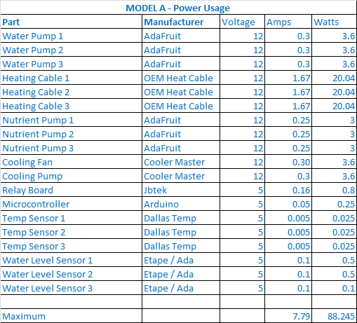
Max Power Consumption
04/24/2015 at 04:22 • 0 commentsHere is a nice little accounting of where the maximum power requirements of The Smart Garden stand:
![]()
-
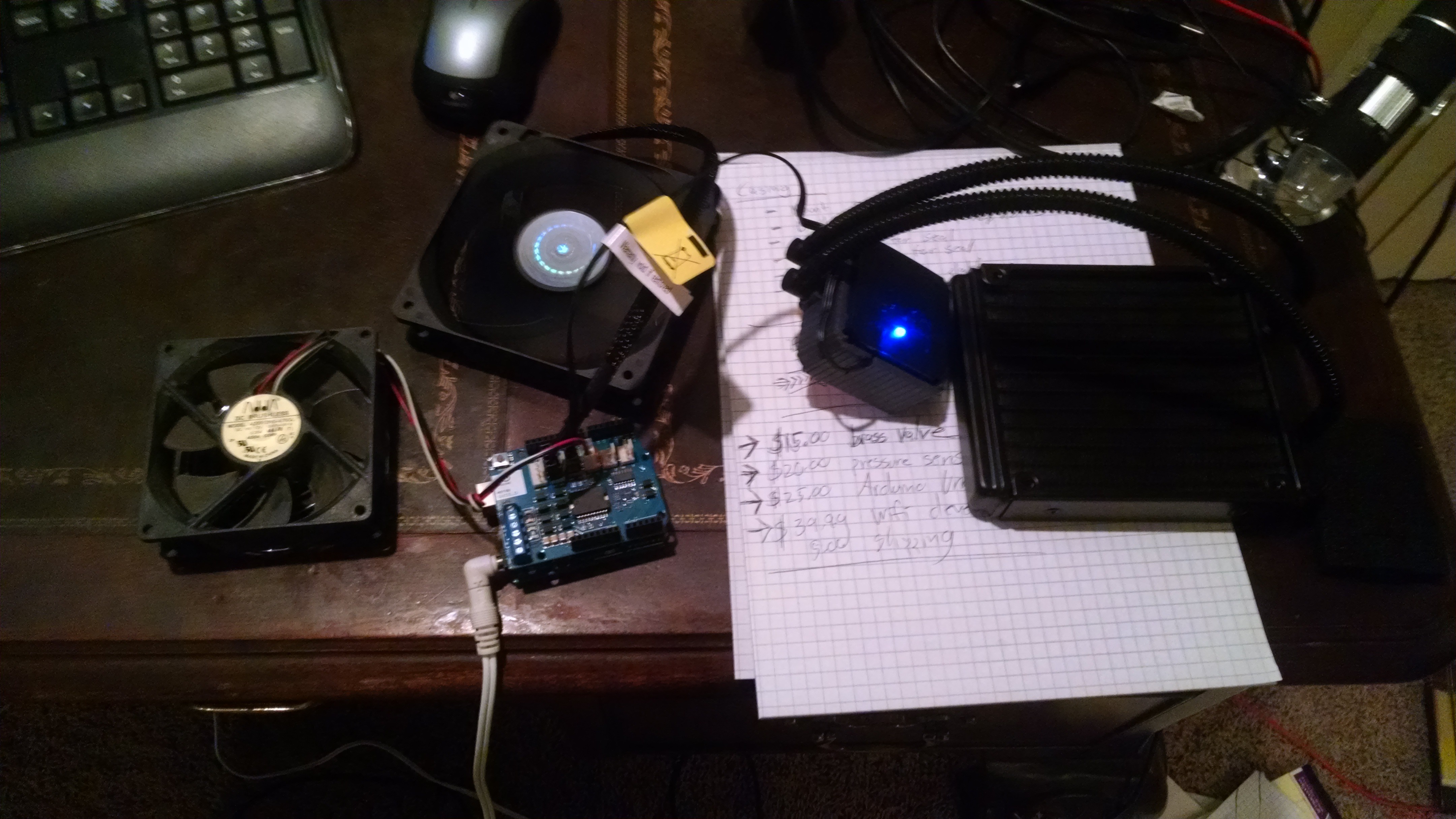
Smart Garden Cooling System
04/21/2015 at 02:35 • 0 commentsI started contemplating how to cool The Smart Garden today. This Cooler Master liquid CPU cooler (the fan in the middle and radiator on the right) worked right out of the box using an Arduino Motor Shield. This is the front runner for the cooling system at this point.
![]()
-
Green Power
04/17/2015 at 14:34 • 0 commentsThe Smart Garden would not be complete without some form of Green Energy...this solar panel will power it eventually.
![]()
-
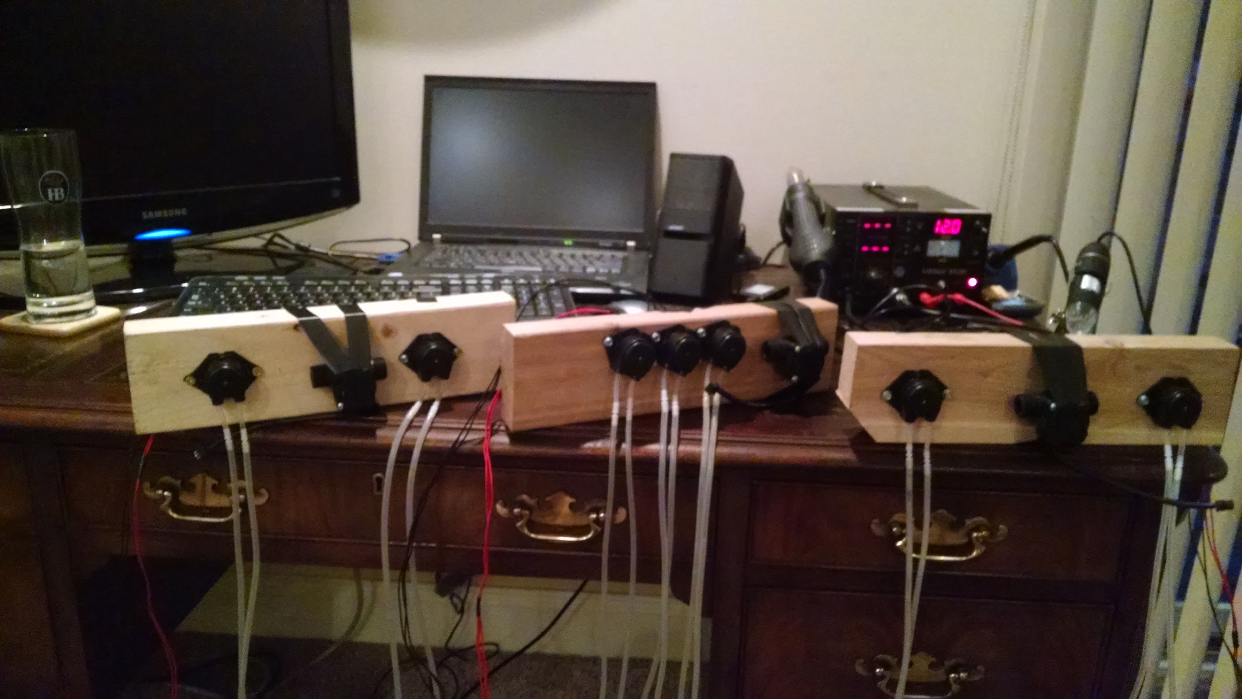
Pumping Station Two
04/17/2015 at 02:03 • 2 commentsWhen growing tomatoes, the chemical balance of the root zone is very important. Too much nitrogen will hurt yield, too little phosphorus will hurt yield...etc. Liquid fertilizers are sold based on different combinations of nitrogen, phosphate, and potassium. The Smart Garden will be able to deliver specific amounts of nutrients to each plant using the pumps shown below:
![]()
The items that are taped on to the pump terminals are flow meters, which will be discussed in detail later.
As noted before, the pumps were found on Adafruit:
https://www.adafruit.com/product/1150
The flow sensors were also found on Adafruit:
-
Breaking Geographic Barriers With Data
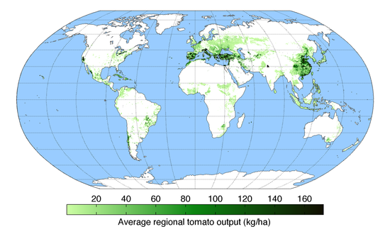
04/15/2015 at 05:00 • 0 commentsJust by looking at the map of worldwide tomato production shown below, it is apparent that transportation costs represent a big factor in providing fresh tomatoes to certain regions of the world.
![]()
The beauty of the IoT revolution is that we can now monitor and analyze the the different variables that cause this apparent fragmentation of the density of produce production. The first Smart Garden is programmed based on my research regarding optimal tomato growth, however, all data will be logged for implementation into future efficiency gains. Just imagine a world where a tomato plant in Illinois is warned about a cold snap coming from Minnesota...or buying a Smart Garden from the store, and using your mobile phone to program it to the optimal setting based on the atmospheric conditions of your location. The possibilities are endless! Implementation of an IoT framework is of the utmost importance for this project.
-
Efficient Space Utilization
04/14/2015 at 20:52 • 0 commentsWhen contemplating the utilization of space of my robotic garden, I thought back to my favorite story highlighting wealth creation abilities of my favorite business leader in history:
While seeking a way to improve the efficiency of the exterior floor plans of the restaurants he operated, this man decided that the heating and air conditioning systems on the side of the building were an inefficient use of space. He called up his HVAC company, and told them that he wanted them to install the machines on the rooftop of his restaurants...they thought his idea was crazy, but ended up fulfilling his odd request. To this day, despite the ample space on the side of most buildings, suburban and rural commercial buildings have these machines on the roof.
The Smart Garden's place in the farming landscape is to provide a backyard appliance for the suburban residential setting, and more importantly, to enhance the viability of the green roof by providing not just energy efficiency to the large building, but also a profitable food byproduct. In this way, the Smart Garden pays homage to this great businessman.
-
Smart Garden Tarp is Off!
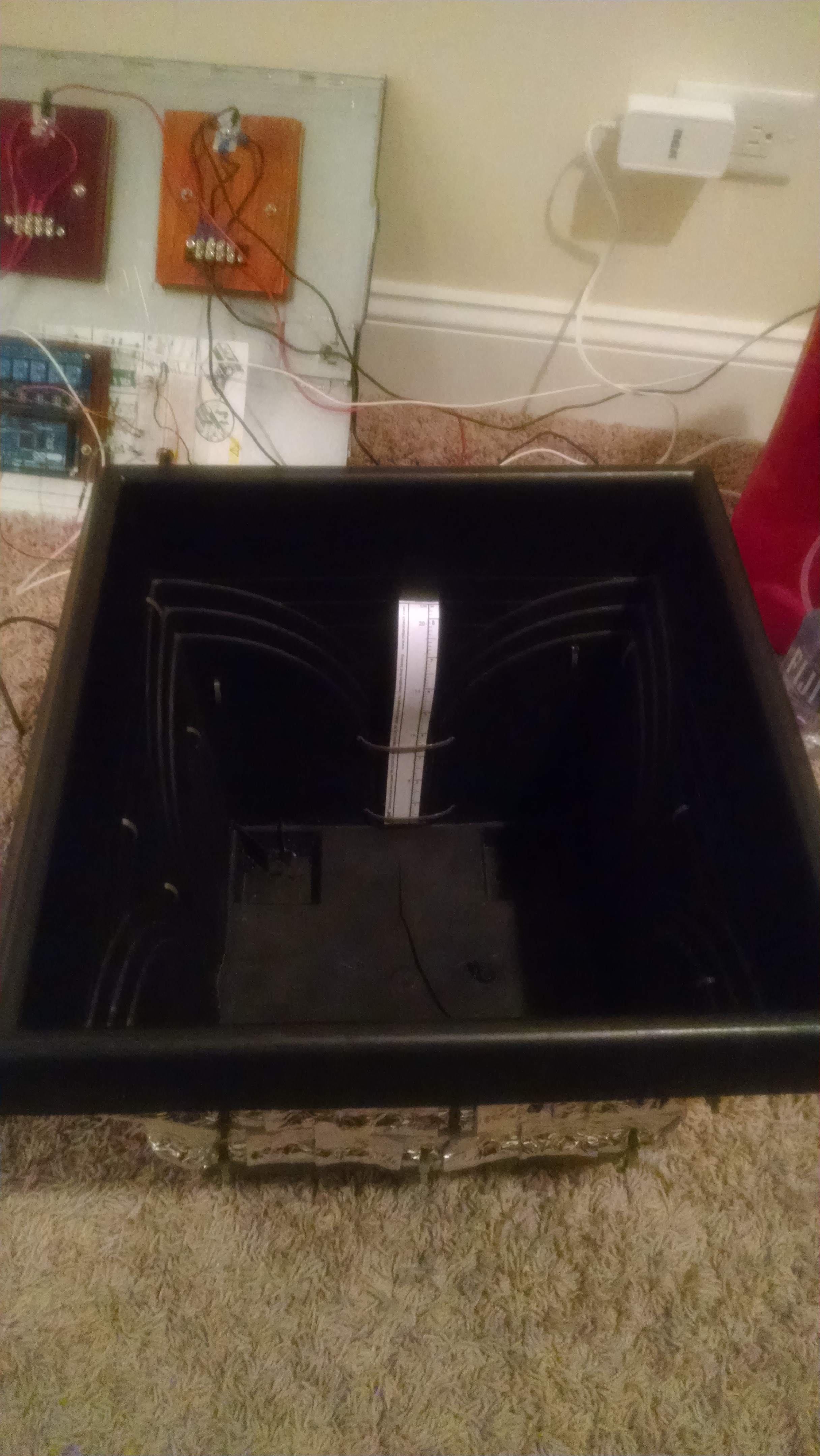
04/14/2015 at 18:48 • 0 commentsWith the tarp off, The Smart Garden is starting to show its form! As previously stated, this project is aiming to mimic the science of a car engine. For any mechanics out there, think of the Smart Garden components like this:
Root System = Car Engine (In this case, I am working with a straight line 3 cylinder)
Arduino Board = Powertrain Control Module
8-Channel Relay = Power Distribution Center
Water Level Sensor = Fuel System Sensors
Temperature Sensor = Radiator Thermometer
Heat Cables and Fan = Radiator System
![]()
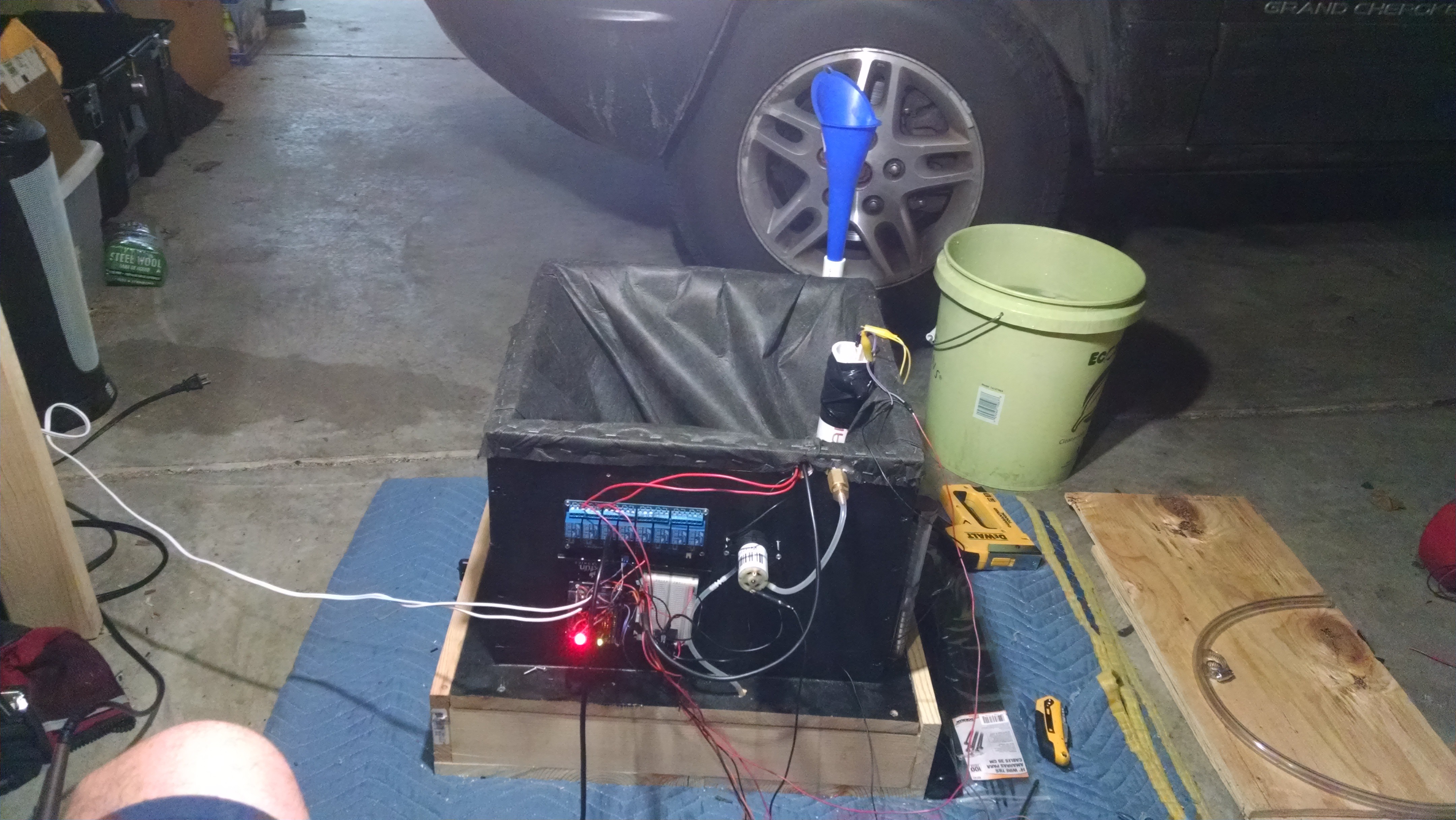
You can also see how I am taping up the wiring similar to the wiring in a car engine (I still need to drill the temp sensor and water pump into the planter):
![]()
-
Water Consumption - The Plant Knows Best
04/10/2015 at 01:08 • 0 commentsProviding the correct amount of water and nutrients to the plant is crucial. Too much water and the plant dies, too little water and the plant dies. For that reason, I will let the plant decide. I placed a liquid level sensor in the planter. When the water level gets low the sensor will tell the Arduino to turn on the water pump. This sensor was found on Adafruit.
https://www.adafruit.com/product/464
![]()
 - Explanation of its functions will also be provided at the new project page: