 alpha_ninja
-
This project's future
08/24/2015 at 19:01 • 0 commentsHello,
as you may have noticed, this project did not make the cut for the quarterfinals.
For this reason, I won't be continuing development of Modular Vertical Farming—I cannot justify the investment it would take. I may reenter this next year, but until then, development will be stopped.
-@alpha_ninjaP.S. Congratulations to those that moved on! :D
-
Connection Considerations
06/20/2015 at 16:40 • 0 commentsTo begin with, I'm sorry for not posting in a long time—I hope I will be able to make a lot of updates over the next few days. Regardless, this won't be a long project log.
I've decided to use the Teensy-LC I got as a prize a few weeks back as the section controller.
The main reason is because of its USB capabilities. In fact, it turns out it's relatively easy to use as a raw HID, meaning that sending 64-byte packets between any computer and the teensy is a breeze.
It also has a relatively high clock speed, so that's great.
I'll be doing some testing & coding for this over the next few days and will keep you updated.
Goals for software: (I'll most likely be using python)
- Figure out some kind of protocol
- Get that protocol implemented
- Both controller and computer-side
- Run a simulation on the teensy for testing
- Both controller and computer-side
- Get some basic GUI going computer-side
I will eventually get a π set up, connected to the teensy, connected to a few modules.
-
Module PCB assembly and testing
05/22/2015 at 02:22 • 0 commentsTo begin with, I now have a twitter account. I'll be using it mostly for posting minor progress updates, so feel free to check it out : @not_beta_ninja
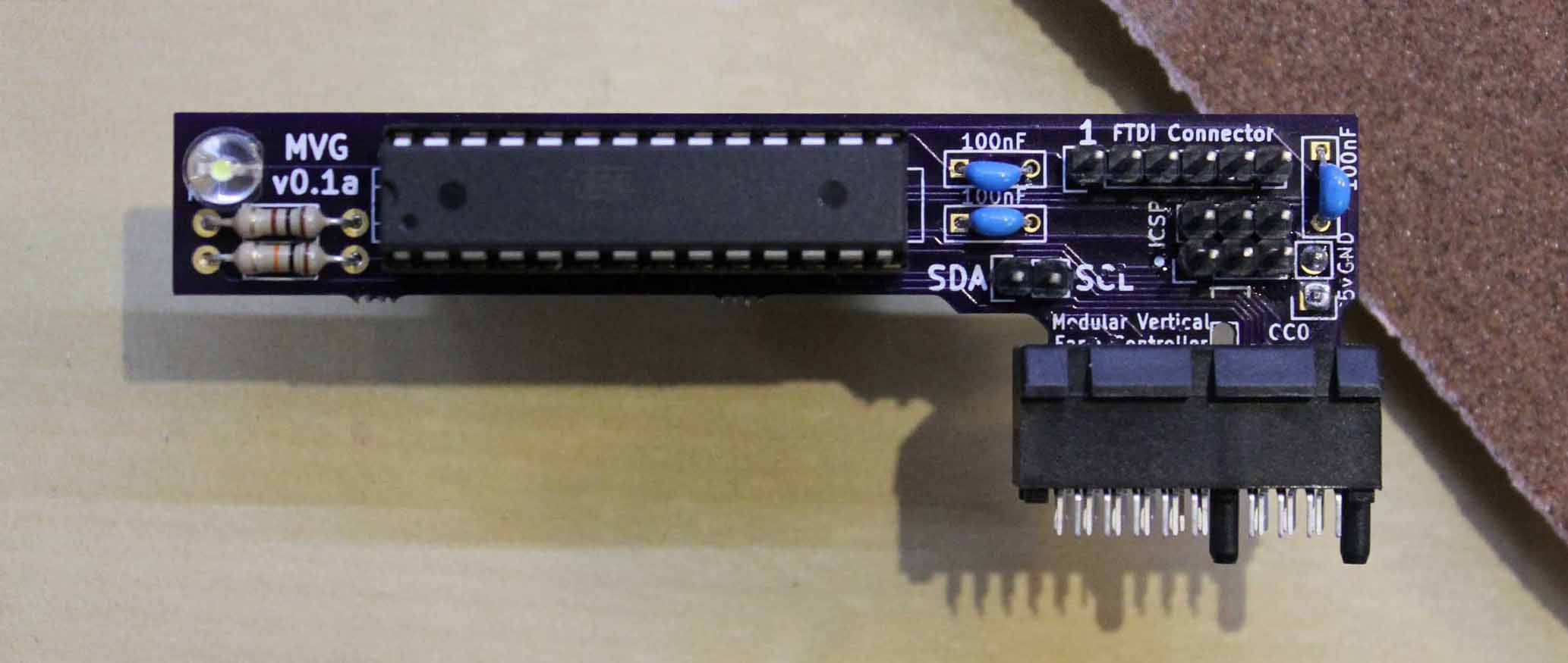
Now, I'd like to apologize for taking so long to post this (well, nine days. It could be worse :] ). Anyway, here's the board assembled and sanded, fit in a PCIe x1 connector. I decided to put the power pins on the back because they would otherwise be blocking the ICSP pins. Design flaw, maybe, but meh. This is just a prototype ;)
![]()
It's a pretty tight fit, and one of the boards required a tiny bit of additional sanding in the cutout just to fit, so I'm going to make the connector a bit thinner. No other complaints on the boards though—they came out great!
Now, on to testing.
I began with a simple power-on test. Worked! (I preloaded the chip with a blinking sketch with an Arduino NG, using the excellent barebones ATMega board files for the Arduino IDE)
I continued with testing FTDI—no problems. I'm pretty happy I didn't swap TX and RX :P
Then, I tested the ICSP. That worked great too. I think I'm going to leave out the FTDI connector on future boards, simply because it's not really necessary. TX and RX are still in the connector design, and since I want to keep the UART broken out, I'll just leave that as it is.
Finally, I loaded up my I²C sketch. It worked communicating with an Arduino UNO, except for a small bug that was quickly squashed ;)
Also, I just checked the resistance through the connector. I'm getting about 0.3 Ohms, which is great.
What I'll be working on next is:
- LED control—I'll probably use some white LED strips I have laying around
- Solenoid control—I have no clue what to test this with, so ordering one or two of those valves from ebay is probably the easiest solution.
- Connector board—I've already designed the connector footprint in KiCad (as always, ask if you want any files!) but I want to get those other things done first.
Thanks for reading, have a nice day (or night!)
Edit 2015-05-26: 0.3 ohms, not 3 ;)
-
PCBs arrived.
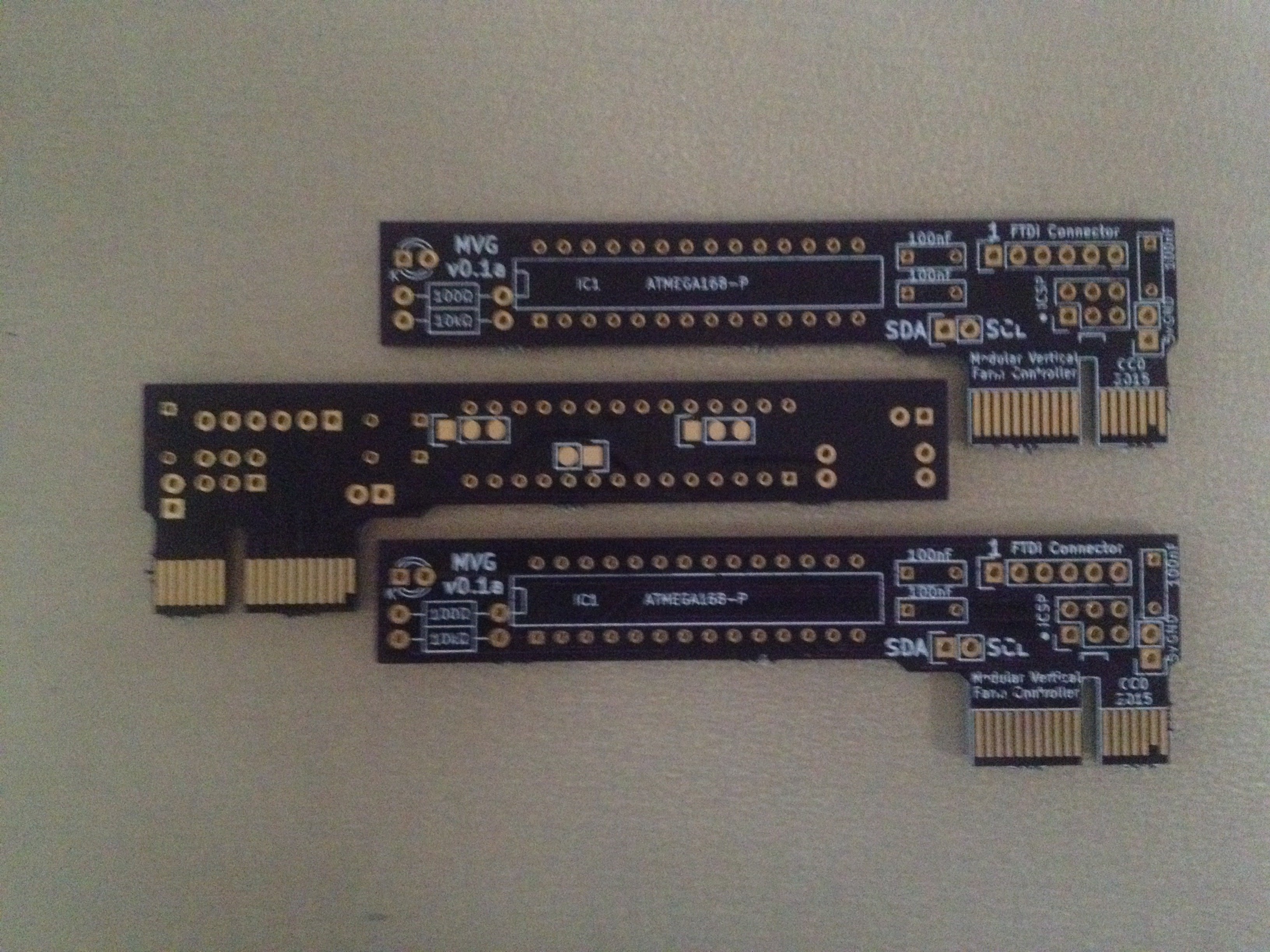
05/13/2015 at 02:07 • 0 commentsThe PCBs arrived from OSHPark!
![]()
I really don't want to do this now, but I'll need to assemble it and sand down the PCIe connector.
-
Stop! Hardware Time.
04/27/2015 at 00:12 • 0 commentsTo begin with, I'd love to thank you all for following/skulling this project and the Hackaday team for choosing me for the prize last week.
I've been doing some work on the hardware aspect of the project (mostly the module part.)
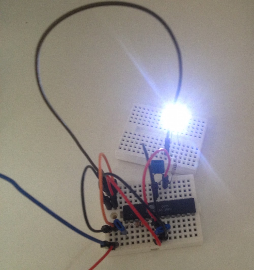
I started up by whipping this up (please excuse the messiness of the wires):
![]()
I tested it, and I²C, FTDI, and ICSP all work great!
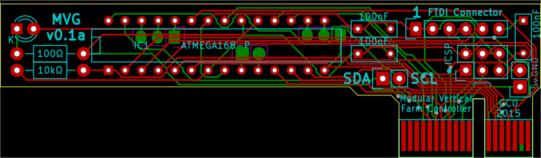
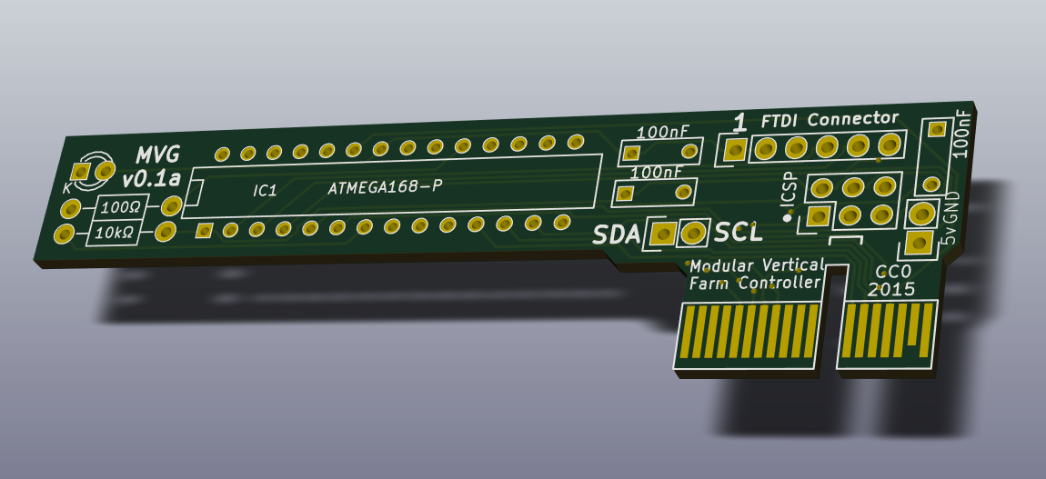
Then, I went on to KiCad. I'm not going to post the schematic because it's just too chaotic, but long story short, here's the preliminary board design:
![The PCB design]()
![A render from KiCad.]()
I'll be ordering this from OSHPark soon, but I'll go through a lot of revisions before I'll be done. For example, you might have noticed that the above boards don't include the mosfet and connections that will be necessary for the grow lights or the hygrometer connections. I will eventually remove all connections aside from the PCIe-ish connector and those necessary for the lights and the hygrometer.
I'll upload the KiCad Files to the github repo when I feel it's a bit more stable, but if any of you want to see them, just ask.
-
Module Electronics & Connections
04/22/2015 at 04:30 • 0 commentsSo, I think I've found a good solution for electrical connections between the frame and module. To recap, we need the following connections:
GND, SCK, SDA, SOL (solenoid), 12V (for led strip), 5V (for microcontroller.)
Now, I've decided to add another 6 pins for module location sensing (which decides the module's I²C address). That brings us to a grand total of 15 pins.
Of course, something that will used so often in the frame and module needs to be cheap.
I think I've found the cheapest thing I will. It's ubiquitous, cheap, and the male connector is the circuit board itself.
PCIe. Of course it will need sanding on the module PCBs, but I'm sure that will cost much less than most other connectors would in the end. I'll use the 36-position version (that's PCIe x1).
About module location sensing: I'm not sure what would make sense in an industrial context, but cut-traces (to ground) on the frame PCBs should be enough for me.
If you're worried about currents being too high for the connector: LED grow light strips seem to take around 600mA/m and the PCIe connector I linked is rated for 1.1A. Just to be safe, I'll probably use more than one pin for this, so I should be good on that front.
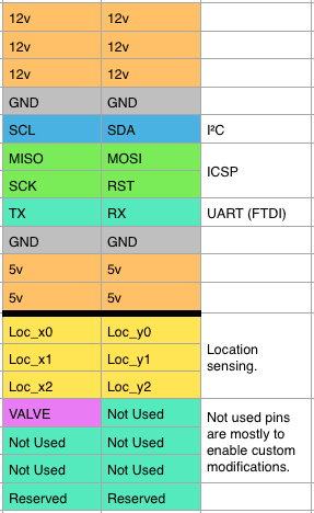
I've decided on this pin allocation:
![]()
I didn't stay that close to the original PCIe allocation in the end.
Edit 2015-04-25: Added UART connections
About connections within the module: I originally planned to have the microcontroller within the bottom bezel of the board. However, it might make more sense to move this to the top - it is shielded from water there anyway, it's closer to the grow LEDs, and I might get away with one circuit board per module! (apart from the hygrometer). I'm probably going to leave out the indicator LED. Instead, whoever performs maintenance on the system will be able to press a button that causes problematic modules to flash their lights, indicating where they are.
If you have any thoughts on this, please post a comment. Thanks!
-
I²C troubles & MCU ideas
04/19/2015 at 21:38 • 0 commentsI²C is great.
When it works.
I've been doing a lot of work on the controller-module communication—and, while doing so, I've learned a lot.
- The Raspberry Pi I²C implementation would be a lot better if it had support for clock stretching.
(I probably won't be using πs as part of this project.) - The Arduino Wire library, which I'm probably going to use, has a really weird bug. I'm not sure if it's specific to that library, but it's annoying as all hell
So, want to know more about that bug?
Here it is.
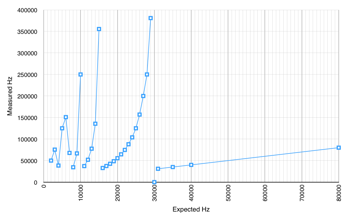
![]() Yep.
Yep.So, using the line of code you'll find anywhere when you search for "arduino change i2c frequency", this mess comes out. I'm assuming the stuff at the far left is a result of the exponential curves being shorter than I could detect using 1kHz steps. I'm using an Arduino UNO as master and Arduino NG as slave. I'm using this code:
TWBR = ((16000000L / I2C_HZ) - 16) / 2;If you're wondering, I've been experimenting around mostly to see what frequencies I can safely use for this project - the signal will have to go several meters, after all.
On a slightly unrelated note: I've been thinking about I²C addresses. Here's my thoughts.
I've decided it makes most sense to add a few pins to the module-frame connections to tell modules where they are (and use that to calculate their address). This means 6 extra pins are needed per module. Theoretically, less could be used with voltage-dividing by resistors and using the analog inputs on the AVRs.
The addresses should then be assigned based on the top-left position of the module.
The address for a given spot is:
(row + 1) << 3 + col
Thus, each controller should have, at most, 8x8 space for modules (that's 2,40m × 2,40m or [7' 10.5" × 7' 10.5"]). I think this should be enough.
Examples of addresses (with (x | y) positions):
top left (0 | 0) - 0001000
bottom left (0 | 7) - 1000000
top right (7 | 0) - 1000000
bottom right (7 | 7) - 1000111The reason for the row codes starting at one is that some I²C addresses beginning with 000 or 111 are reserved.
This method leaves addresses beginning with 101, 110, 0001, and 1110 completely free (that's 48 additional slaves, while leaving the possibility for future use of 10-bit addresses open)
Of course, it is possible to use I²C switches, but I doubt that will be necessary for my prototypes.
Another thing: I'll probably use AtMEGA168s for the modules. They seem to be the cheapest AtMEGAs on mouser (in a SMD package), and the AtTINYs I was considering (AtTINY441 - the simplest ones with EEPROM and TWI / I²C) are cheaper by only a few cents and not quite as strong.
For the controllers, a normal arduino is probably all that's necessary. I'll probably use an ethernet connection in the future.
- The Raspberry Pi I²C implementation would be a lot better if it had support for clock stretching.
-
Docking deliberations
04/12/2015 at 18:10 • 0 commentsHey there!
I'd like to write a bit about the docking the modules and connectors used today.
I've chosen 30cm as the minimum side length for the modules. This is since most small-ish gardening pots are around 12" in diameter (about 30cm). Of course, multiples of that figure will be allowed.
As has been previously determined, each slot will have LED power, solenoid enabling & disabling (to reduce necessary connections: high-impedance for off, GND to enable. The solenoid will be connected to 12V power on the other side), I²C, +5V, and ground connections. (coming up to 6 ports, assuming a common ground is used.)I've decided to use normal pin headers (the 0.1" pitch type) for the prototype, but give them a protective shrouding that also aligns them. I'm not sure yet just how, but I'll verify that they can be only plugged in one way, probably with a missing pin or a half-pin offset, as can be found on arduinos.
Thus, the electrical connections are:
GND, SCK, SDA, SOL (solenoid), 12V (for led strip), 5V (for microcontroller.)
There are two water connections:
Irrigation (solenoid with pressure reducer will be in the frame)
Extra water (might eventually lead to a water filtering system.)
I'm not sure whether I want the modules to lock into the frame. It's probably not worth the extra cost. I do, however, want some plastic protrusions that align the module to the correct location upon insertion.
Automated removal and insertion of modules will be relatively easy. Since the modules have overhangs on the sides, robots can latch into these and pull it directly out. It would probably be good to have alignment markings on the modules in this case, though - this would also benefit computer vision setups that monitor the plants.
-
Organizational Structure
04/06/2015 at 07:30 • 0 commentsAn image depicting the organizational structure I plan of having:
![]() I've thought a bit about the organizational structure of the project. I've come to the following conclusions:
I've thought a bit about the organizational structure of the project. I've come to the following conclusions:- Modules should not "think on their own", but rather do the following things when the controller requests them:
- Enable/disable grow lights
- Give Hygrometer readings
- Change status indicators
- Report their unique ID, module size (!), plant type (?)
- Plumbing should be handled by the controller. It should control the valves based on the reported hygrometer status. It is probably a good idea to do one of the following:
- Have a valve for each module, directly controlled. Better precision in plant watering.
- Have a valve for each module, directly controlled. However, the valve power would run through the module, ensuring water doesn't flow unless a module is present. The controller can only turn all on or off. (Makes controllers easier, but probably not worth price of extra valves - 1. probably a better idea)
- Have a valve for each module, controlled by the module. The controller would probably tell the module whether it should water itself. The controller won't have to control so much with this approach.
- Have a valve for each section. In this case, missing modules would mean water leaks, but this can be averted by asking all positions for their modules (and the modules' sizes) and simply waiting until every position is populated. This might require dummy modules that don't permit water from entering to plug the water connection.
- Have a valve for each section. Figure out a way to (mechanically) shut off water flow if no module is present. Although this may be more preferable than 3., this would likely bulk up the frame more than I'd want. Some kind of lever connected to a spring pushing it to close the silicone tube
Should 1. - 3. be chosen, a transistor should probably be incorporated into the frame (near the valve) for switching the valve. - Grow Lights
While solutions 1. (controller controls directly), 3. (module controls for controller), or 4. (controller controls all directly) above could be applied to this (2. and 5. are pointless because no power is lost should a module not be attached.), I'm tending to 3. or 4. The reason it might be nice to control LED strips individually is the different growth cycles of different plants. Different seasons could be simulated for different plants this way.
Should 3. be chosen, a transistor should probably be incorporated into the module for switching the lights. - Thermometers
Probably connected to a microcontroller that can communicate directly with the section controller.
- Modules should not "think on their own", but rather do the following things when the controller requests them:
-
Modeling & Module Meditations
04/03/2015 at 14:14 • 0 commentsI have begun with modeling the plant containers, for which I'm using OpenSCAD.
Here's a picture of my current progress:![]() The plants, soil, and watering tube are in the image to clarify usage.
The plants, soil, and watering tube are in the image to clarify usage.Finished modules will contain: (not a final BOM yet. Just some thoughts)
- ~ $0.30: a small LED indicator (probably a red/green LED),
- ~ $3.50: a microprocessor (probably an atmega, not sure which one yet)
- $???: connections for power and I²C (I've had problems finding good electrical connectors for this application. Any ideas?)
- ~ $4.00/m: LED strip(s) to provide light (likely red/blue)
- Irrigation connector (likely normal 1/4" irrigation connector and tubing for prototypes)
- ~ $2.00/m: Irrigation tubing (probably silicone)
- ~ $1.50 Soil humidity sensor (the price is for one you'd find on amazon. I might be able to integrate this to the board [and seal it off with silicone], thus reducing costs.)
I'll post the .scad files eventually (when I have figured out the mounting and connection methods I want to use and have integrated those into the model.)
The container will likely be 3d-printed for the prototypes. Injection Molding would be preferable (after optimization therefore) for a larger-scale run.
Modular Vertical Farming
Growing food where it's needed, ready to be sold.
 Yep.
Yep.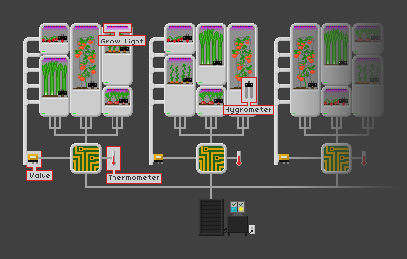 I've thought a bit about the organizational structure of the project. I've come to the following conclusions:
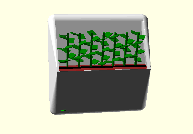 The plants, soil, and watering tube are in the image to clarify usage.